EP1466100B1 - Bohrlochkompressor - Google Patents
Bohrlochkompressor Download PDFInfo
- Publication number
- EP1466100B1 EP1466100B1 EP03731743A EP03731743A EP1466100B1 EP 1466100 B1 EP1466100 B1 EP 1466100B1 EP 03731743 A EP03731743 A EP 03731743A EP 03731743 A EP03731743 A EP 03731743A EP 1466100 B1 EP1466100 B1 EP 1466100B1
- Authority
- EP
- European Patent Office
- Prior art keywords
- compressor
- gas
- rotor
- bearings
- motor
- Prior art date
- Legal status (The legal status is an assumption and is not a legal conclusion. Google has not performed a legal analysis and makes no representation as to the accuracy of the status listed.)
- Expired - Lifetime
Links
- 238000011144 upstream manufacturing Methods 0.000 claims abstract description 11
- 238000004804 winding Methods 0.000 claims abstract description 3
- 239000007789 gas Substances 0.000 claims description 124
- 238000004519 manufacturing process Methods 0.000 claims description 12
- VNWKTOKETHGBQD-UHFFFAOYSA-N methane Chemical compound C VNWKTOKETHGBQD-UHFFFAOYSA-N 0.000 claims description 6
- 238000001816 cooling Methods 0.000 claims description 4
- 239000003345 natural gas Substances 0.000 claims description 3
- 238000004064 recycling Methods 0.000 claims 1
- 238000012546 transfer Methods 0.000 description 8
- 238000013461 design Methods 0.000 description 5
- 241000239290 Araneae Species 0.000 description 4
- 239000007788 liquid Substances 0.000 description 4
- 238000010586 diagram Methods 0.000 description 3
- 210000004907 gland Anatomy 0.000 description 3
- 239000013618 particulate matter Substances 0.000 description 3
- 230000006835 compression Effects 0.000 description 2
- 238000007906 compression Methods 0.000 description 2
- 238000009833 condensation Methods 0.000 description 2
- 230000005494 condensation Effects 0.000 description 2
- 230000000694 effects Effects 0.000 description 2
- 230000006698 induction Effects 0.000 description 2
- 230000002093 peripheral effect Effects 0.000 description 2
- 241000555745 Sciuridae Species 0.000 description 1
- 230000003466 anti-cipated effect Effects 0.000 description 1
- 238000013459 approach Methods 0.000 description 1
- 238000004891 communication Methods 0.000 description 1
- 239000002826 coolant Substances 0.000 description 1
- 230000001419 dependent effect Effects 0.000 description 1
- 238000001125 extrusion Methods 0.000 description 1
- 239000012530 fluid Substances 0.000 description 1
- 230000002706 hydrostatic effect Effects 0.000 description 1
- 239000012535 impurity Substances 0.000 description 1
- 238000002347 injection Methods 0.000 description 1
- 239000007924 injection Substances 0.000 description 1
- 239000000314 lubricant Substances 0.000 description 1
- 238000012423 maintenance Methods 0.000 description 1
- 239000000463 material Substances 0.000 description 1
- 238000000034 method Methods 0.000 description 1
- 230000001151 other effect Effects 0.000 description 1
- 238000011084 recovery Methods 0.000 description 1
- 238000005096 rolling process Methods 0.000 description 1
- 238000000926 separation method Methods 0.000 description 1
- 230000003068 static effect Effects 0.000 description 1
- XLYOFNOQVPJJNP-UHFFFAOYSA-N water Substances O XLYOFNOQVPJJNP-UHFFFAOYSA-N 0.000 description 1
- 238000003466 welding Methods 0.000 description 1
Images


Classifications
-
- F—MECHANICAL ENGINEERING; LIGHTING; HEATING; WEAPONS; BLASTING
- F04—POSITIVE - DISPLACEMENT MACHINES FOR LIQUIDS; PUMPS FOR LIQUIDS OR ELASTIC FLUIDS
- F04D—NON-POSITIVE-DISPLACEMENT PUMPS
- F04D29/00—Details, component parts, or accessories
- F04D29/05—Shafts or bearings, or assemblies thereof, specially adapted for elastic fluid pumps
- F04D29/056—Bearings
- F04D29/057—Bearings hydrostatic; hydrodynamic
-
- F—MECHANICAL ENGINEERING; LIGHTING; HEATING; WEAPONS; BLASTING
- F04—POSITIVE - DISPLACEMENT MACHINES FOR LIQUIDS; PUMPS FOR LIQUIDS OR ELASTIC FLUIDS
- F04D—NON-POSITIVE-DISPLACEMENT PUMPS
- F04D25/00—Pumping installations or systems
- F04D25/02—Units comprising pumps and their driving means
- F04D25/06—Units comprising pumps and their driving means the pump being electrically driven
-
- F—MECHANICAL ENGINEERING; LIGHTING; HEATING; WEAPONS; BLASTING
- F04—POSITIVE - DISPLACEMENT MACHINES FOR LIQUIDS; PUMPS FOR LIQUIDS OR ELASTIC FLUIDS
- F04D—NON-POSITIVE-DISPLACEMENT PUMPS
- F04D29/00—Details, component parts, or accessories
- F04D29/58—Cooling; Heating; Diminishing heat transfer
- F04D29/5806—Cooling the drive system
-
- F—MECHANICAL ENGINEERING; LIGHTING; HEATING; WEAPONS; BLASTING
- F04—POSITIVE - DISPLACEMENT MACHINES FOR LIQUIDS; PUMPS FOR LIQUIDS OR ELASTIC FLUIDS
- F04D—NON-POSITIVE-DISPLACEMENT PUMPS
- F04D29/00—Details, component parts, or accessories
- F04D29/58—Cooling; Heating; Diminishing heat transfer
- F04D29/582—Cooling; Heating; Diminishing heat transfer specially adapted for elastic fluid pumps
- F04D29/584—Cooling; Heating; Diminishing heat transfer specially adapted for elastic fluid pumps cooling or heating the machine
-
- F—MECHANICAL ENGINEERING; LIGHTING; HEATING; WEAPONS; BLASTING
- F04—POSITIVE - DISPLACEMENT MACHINES FOR LIQUIDS; PUMPS FOR LIQUIDS OR ELASTIC FLUIDS
- F04D—NON-POSITIVE-DISPLACEMENT PUMPS
- F04D13/00—Pumping installations or systems
- F04D13/02—Units comprising pumps and their driving means
- F04D13/06—Units comprising pumps and their driving means the pump being electrically driven
- F04D13/08—Units comprising pumps and their driving means the pump being electrically driven for submerged use
- F04D13/10—Units comprising pumps and their driving means the pump being electrically driven for submerged use adapted for use in mining bore holes
Definitions
- the present invention relates a downhole compressor, i.e. a compressor designed to be lowered into a well of a natural gas reservoir to assist in extracting gas from the reservoir.
- the present invention seeks to provide a rotary compressor which is suitable for use as a downhole compressor in that its gas bearings can be operated over very prolonged periods without requiring attention and in that its electric motor is adequately cooled by the produced gas.
- a compressor designed to be lowered into a well of a natural gas reservoir to assist in extracting gas from the reservoir
- the compressor comprising a casing, a rotor mounted within the casing, an electric motor for driving the rotor having a stator with windings stationarily mounted in the casing and an armature formed as part of the rotor, and gas bearings supporting the rotor for rotation relative to the stator, the gas bearing being arranged at the upstream and downstream opposite ends of the motor, characterised in that a bladed impeller wheel for compressing the production gas from the reservoir is mounted on an overhanging end of the rotor that projects beyond the gas bearing at one end of the motor, such that all the gas bearings of the compressor and of the electric motor are arranged on the same side of the bladed impeller wheel, and during operation, the production gas flows over and serves to cool the electric motor.
- the bladed impeller wheel herein also termed the main compressor, is overhung.
- the design of the motor rotor with an overhung compressor permits the rotor to be made hollow so that it can be better cooled.
- the main compressor is arranged at the upstream end of the rotor and an auxiliary compressor is mounted on the opposite end of the rotor, the auxiliary compressor drawing gas from downstream of the main compressor and serving to supply the gas after further pressurisation to the bearings of the rotor.
- both compressors can be overhung so that all the bearings are situated axially between the main and auxiliary compressors.
- the auxiliary compressor may itself be an axial compressor or other type of dynamic compressor.
- dynamic compressor is used here to include rotary compressors that produce axial and/or radial flow and thus in particular includes both axial, mixed and centrifugal compressors.
- a purifier may be provided in the intake of the auxiliary compressor to remove particulates or other impurities suspended in the produced gas.
- the purifier may conveniently be an inertial separator.
- the gas for the gas bearings flows in the opposite direction to the main axial gas flow of the produced gas.
- the gas can be discharged into the main flow of the produced gas after it has passed through the bearings, it is preferred to cool the gas by transferring heat from it to the main flow of produced gas, whereupon the gas can be recycled to the bearings by being returned to the intake of the auxiliary compressor. In this way, it is possible for the gas supplied to the gas bearings to flow essentially in a closed circuit.
- the purifier does not have to be able to remove the particulate matter in all of the produced gas and it is therefore able to function reliably over prolonged periods of time.
- the purifier may even be a simple filter.
- modules, and/or a set of modules in tandem may be disposed at various depths in the production tube of a well in order to optimise the upward movement of droplets and inhibit the condensation of vapour.
- reference numeral 1 designates the production tube of a well
- numeral 2 designates the outer shell of a compressor
- numeral 3 refers to the casing of an electric motor.
- the casing of the motor is held concentrically within the shell of the compressor by the fixed blades 4 of the compressor and by the arms of a spider 5.
- the motor is a high frequency induction motor and is supplied with high frequency current via an umbilical that is not shown in the Figure. Typically the speed of the motor is in the range of 20,000 rpm to 50,000 rpm.
- the preferred electric motor has a stator 6 and a permanent magnet armature or rotor 7 but it would be possible to use an alternative form of induction motor, such as a squirrel cage motor.
- the rotor of the compressor of which the armature of the motor forms a part, is designated 8.
- the rotor runs in journal bearings 9 and 10, and thrust is taken by a thrust bearing having a collar 11.
- the motor drives the wheel 12 of the dynamic compressor which has a bladed impeller wheel 13. Upstream of the impeller wheel 13 are the inlet guide vanes 14 that also hold concentrically the segment of an inner casing 15.
- the compressor is constructed as a module.
- a complete module is spanned by A, a next module downstream of A is indicated at B, and C is an inlet nose fairing to be fitted to a single module or to the first of a number of coupled modules.
- the cone D is a diffusing cone to be fitted at the exhaust of a module or at the exhaust of the last of a number of modules connected in tandem, i.e. one after the other in the direction of gas flow.
- FIG. 2 shows a detail of a compressor module that differs from the module A of Figure 1 in that it has two compressor stages, i.e. two bladed impeller wheels 13a and 13b.
- One or more stages may be provided in dependence upon the duty to be performed, the power of the motor, and what is found to be the design optimum in each application.
- Gas bearings are used because of the speed of the compressor and because they can use as a lubricant a fluid already present, namely the produced gas. Gas bearings offer lower friction than water or oil lubricated bearings. Rolling element bearings would have too short a life expectancy under the onerous down well conditions.
- journal bearings (designated 9 and 10 in Figure 1) will react little load and hence will most likely be of a hydrostatic type.
- Such bearings rely on the injection of gas at high pressure to separate the contacting surfaces. This high pressure gas is provided by the auxiliary compressor once it has achieved a sufficiently high rotational speed.
- the thrust bearing (designated 11 in Figure 1) will carry continuous load and therefore will be of a hydrodynamic type achieving separation by a self-generated film once the shaft reaches a sufficiently high speed.
- the heat generated by the electrical losses of the motor is removed by passing the heat to the flow of gas, the produced gas being the sole cooling medium available.
- Figure 3 An embodiment of the invention that includes gas bearings is illustrated diagrammatically by Figure 3.
- the Figure illustrates a version of the module that is designated A or B in Figure 1.
- the production tube of the well is designate 301, the outer shell of the compressor 302, while numerals 303a and 303b refers to a double casing of the motor.
- the casing of the motor is held concentrically within the shell of the compressor by stationary blades 304 of the compressor and by the arms of a spider 305.
- the stator of the motor is shown at 306 and its armature at 307.
- the hollow rotor of the compressor of which the armature of the motor is a part, is designated 308.
- the rotor runs in the journal bearings 309, 310, and thrust is taken by a thrust bearing having a collar 311.
- the motor drives the wheel 312 of the dynamic compressor with its impeller blades 313. Upstream of the compressor are the inlet guide vanes 314 that also hold concentrically the segment of inner casing 315, and downstream at 304 are the fixed blades.
- the compressor propels gas into the principal annular channel X that is the channel for the main flow of the produced gas, but also into an annular channel Y bounded by the walls 303a and 303b of the casing of the motor.
- Annular channel Z is formed by the space between the outer casing 302 of the compressor and the production tube 301.
- the channel Z is closed at each end by annular plates that fit as closely as is practicable into the bore of the production tube.
- the pressure in channel Z is maintained by ports Z1 substantially at the pressure upstream of the inlet guide vanes 314.
- the gas that flows through channel Y flows over an extended heat transfer surface at Y1 that by welding, or other method of fixing, is in intimate thermal contact with the inner motor casing 303a.
- the extended heat transfer surface may by way of example comprise a number of fins equally spaced around the circle and extending in a spiral around the inner casing of the motor or axially.
- the gas flows via a purifier Y2 into the inlet of the auxiliary dynamic compressor that is illustrated with two stages and is indicated as an assembly at 316.
- the auxiliary compressor further compresses gas into the volume U that is bounded on the left-hand side in Figure 3 by the journal bearing 310 and by the labyrinth gland 318 that is bolted to the bearing to ensure concentricity.
- the pressurised gas enters the journal bearing 310 by such ports as may be convenient, for example the port shown at 319.
- the gas enters the journal and thrust bearing 309 from the volume U, for example via pipes laid between adjacent fins of the extended heat transfer surface Y1 as indicated by the chain-dotted line L1.
- the volumes V and W are in communication via the air gap between the bore of the stator of the motor and its armature and consequently the gas pressures in these volumes will be substantially equal.
- the volume V and the volume W or both are connected to channel Z by way of hollow spider arms that are not shown and that are necessary to hold concentrically the various casings. It is to be noted that because of through spaces such as the spaces between the pads, the pressures to the left and to the right of a bearing become equalised.
- the inner part of the runner blades 313 together with the auxiliary compressor 316 raise the pressure of the gas from the pressure P1 via the pressure P3 to the pressure P4.
- Gas at pressure P4 flows to the bearings where in essence it is throttled in its escape in to the volumes V and W down to the pressure P1.
- the gas leaking through the labyrinth seal 318 is throttled from the pressure P4 down to the pressure P1.
- the diameter D may be chosen in design so that the axial force produced at the balance piston 317 offsets as great a part as is practicable of the resultant of the other axial forces.
- Figure 4 is a modified version of the embodiment of Figure 3.
- the stationary parts are hatched in the upper part of the figure.
- Figures 3 and 4 may be related one to the other by the element 410 that corresponds to the right hand journal bearing 310 of the compressor shown in Figure 3.
- the auxiliary compressor to the right of the bearing is a two stage centrifugal compressor as opposed to the two stage axial compressor of the embodiment of Figure 3.
- the pressure rise across a centrifugal and an axial flow compressor stage is set by the peripheral speed of the compressor disk, and by the mean peripheral speed of the runner blades of the axial flow stage.
- an axial flow stage When confined within the same diameter casing, an axial flow stage may have a greater mean diameter of its runner blades than the outer diameter of the centrifugal compressor disk because the centrifugal compressor requires a diffuser outboard of its disk, and the axial flow compressor does not.
- This consideration with relation to Figures 3 and 4 may lead to a single stage axial auxiliary compressor in the embodiment of Figure 3 performing the same duty as the two stage centrifugal compressor of Figure 4.
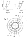
- Figures 5a and 5b are idealised enthalpy-entropy diagrams for the gas flows compressed by the auxiliary compressors of the embodiments of Figures 3 and 4, and then throttled to their initial pressures in the bearings.
- the gas flows in to the module at pressure P1. Downstream of the running blades of the main compressor, in the channel Y, the gas is at pressure P3, and after passage through the auxiliary compressor it enters the bearings at pressure P4. The gas is then throttled down to the pressure P1 at its exhaust from the bearings.
- Constant pressure lines for P1 and P4 are drawn in Figure 5a.
- the inflow of gas occurs at 'a', the gas is compressed to 'b' and then throttled to its outflow at 'c'.
- the inflow is of relatively cool gas, and the outflow is gas heated by the energy input of compression over 'a' to 'b'.
- FIG. 6a and 6b illustrate diagrammatically an embodiment in which such a closed circuit is provided for the high-pressure gas.
- the main compressor is a two-stage axial flow compressor shown at 614, 613, 612 and 604.
- a cylindrical baffle 603b with the casing of the motor 603a form a channel Y in which gas flows over the cooling fins Y1 of the stator of the motor.
- Channel Y, and channel X become a single channel downstream of the baffle.
- the closed circuit will be now described, taking the volume T as its starting point.
- Gas from T flows through the filter 620 in to the intake of the axial flow compressor 616.
- the compressor delivers high pressure gas in to the volume U and from there it passes via ports 619 to the journal bearing 610, and to the journal and thrust bearing at 609 via pipes of which one is at L1.
- the gas is throttled on passing through the bearings and exhausts in one instance first to the volume V, and then via the air gap of the motor to volume W where it joins the exhaust from the other bearing.
- the gas is returned to the volume T via pipes of which one is indicated at L3. Pipes L3 are laid in the channel X where the passing of the main flow of gas past them will cool the pipes and the circulating gas within them.
- the cooling of the gas from 'b' to 'c' depends upon the effectiveness of heat transfer across the tube L3.
- a balance has to be made between the energy input into the circulating gas by the auxiliary compressor, and the heat lost from the circulation through the walls of pipes L3 to the main gas stream.
- the balance is created through the temperature of the circulating gas.
- the gas loses more heat across the walls of the pipes L3 as the gas temperature rises, and at the same time the energy input in to the gas by the compressor falls.
- the gas of the closed circuit will be at the temperature at which heat loss and energy input are in balance. It is desirable that the temperature of the gas at the inlet of the auxiliary compressor should be brought as close as is practicable to the temperature of the flow in the channel X by optimising the gas to gas heat transfer coefficient of the wall of pipes L3.
- the flow resistance in the combined channels X and Y is increased by the intrusion of pipes and fins in to the flow area. For that reason, the main compressor 604, 612, 613, 614 has been changed for illustrative purposes from the compressor of Figure 3 to a two-stage compressor. Whether such a change is needed can only be determined in each particular instance from a design study.
- the auxiliary compressor 616 of Figure 6a is a single stage compressor in comparison with the two stage auxiliary compressor of Figure 3.
- FIG. 6b The section A-A of Figure 6a outboard of the motor casing is illustrated in Figure 6b.
- the cooling fins of the stator are at Y1 between the casing of the motor 603a and the baffle 603b.
- the four pipes L1 run between adjacent fins.
- Eight pipes L3 are illustrated equally spaced around the circle in the channel X.
- the pipes L3 may conveniently be formed as an extrusion with both internal and external fins to enhance the gas to gas heat transfer.
Landscapes
- Engineering & Computer Science (AREA)
- Mechanical Engineering (AREA)
- General Engineering & Computer Science (AREA)
- Physics & Mathematics (AREA)
- Thermal Sciences (AREA)
- Fluid Mechanics (AREA)
- Structures Of Non-Positive Displacement Pumps (AREA)
- Devices That Are Associated With Refrigeration Equipment (AREA)
- Applications Or Details Of Rotary Compressors (AREA)
- Compressors, Vaccum Pumps And Other Relevant Systems (AREA)
- Finger-Pressure Massage (AREA)
Claims (11)
- Verdichter zum Absenken in einen Quellenschacht einer Erdgasspeicherstätte zur Unterstützung des Austragens von Gas aus der Speicherstätte, wobei der Verdichter folgendes umfaßt:ein Gehäuse (2),einen in dem Gehäuse eingebauten Rotor (8),einen Elektromotor (3) zum Antreiben des Rotors, mit einem Stator (6) mit Wicklungen, welcher stationär im Gehäuse eingebaut ist, und einem als Teil des Rotors ausgebildeten Anker (7), undGaslager (9, 10), welche den Rotor dem Stator gegenüber drehbar tragen, wobei die Gaslager jeweils an den stromaufwärtigen und stromabwärtigen, einander entgegengesetzten Enden des Motors angeordnet sind,dadurch gekennzeichnet, daß
ein beschaufeltes Verdichterrad (13) zur Verdichtung des Produktionsgases aus der Speicherstätte an einem überhängenden Ende des Rotors angebracht ist, welches an einem Ende des Motors über das Gaslager hinausragt, so daß alle Gaslager des Verdichters und des Elektromotors auf derselben Seite des beschaufelten Verdichterrades liegen, und
das Produktionsgas im Betrieb über den Elektromotor streicht und so zur Kühlung desselben dient. - Verdichter nach Anspruch 1, worin der Rotor des Verdichters, welcher den Anker des Motors mit verkörpert, hohl ausgebildet ist, um so die Kühlung des Motors zu unterstützen.
- Verdichter nach Anspruch 1, worin das beschaufelte Verdichterrad am stromaufwärtigen Ende des Rotors angeordnet ist, und worin ein Hilfsverdichter am gegenüberliegenden Ende des Rotors montiert ist, wobei der Hilfsverdichter Gas von der stromabwärtigen Seite des Hauptverdichters abzieht und dazu dient, Gas nach weiterer Verdichtung an die Lager des Rotors zu fördern.
- Verdichter nach Anspruch 3, worin beide Verdichter überhängend montiert sind, so daß alle Lager axial zwischen dem Haupt- und dem Hilfsverdichter angeordnet sind.
- Verdichter nach Anspruch 3 oder 4, worin der Hilfsverdichter ebenfalls ein Axialverdichter ist.
- Verdichter nach Anspruch 3 oder 4, worin der Hilfsverdichter ein Zentrifugalverdichter ist.
- Verdichter nach einem beliebigen der Ansprüche 3 bis 6, worin ein Gasreiniger im Ansaugbereich des Hilfsverdichters vorgesehen ist.
- Verdichter nach einem beliebigen der Ansprüche 3 bis 7, worin vom Hilfsverdichter verdichtetes Gas in den Axialstrom von Produktionsgas abgelassen wird, nachdem es durch die Lager geströmt ist.
- Verdichter nach einem beliebigen der Ansprüche 3 bis 7, worin Mittel zur Wärmeübertragung von dem von den Lagern abgeführten Gas auf den Produktionsgasstrom vorgesehen sind, sowie zur Rückführung des gekühlten Gases auf die Einlaßseite des Hilfsverdichters, so daß die Gasversorgung für die Lager in einem im wesentlichen geschlossenen Kreislauf umläuft.
- Verdichtersystem für eine Gasquelle, welches einen oder mehrere Verdichter nach einem beliebigen der vorangehenden Ansprüche beinhaltet, die im Tandem miteinander angeordnet sind.
- Verdichtersystem nach Anspruch 10, mehrere Verdichter oder Verdichtergruppen aufweisend, die in Tandemanordnung an unterschiedlichen Höhen entlang des Bohrlochschachtes der Quelle angeordnet sind.
Applications Claiming Priority (3)
| Application Number | Priority Date | Filing Date | Title |
|---|---|---|---|
| GB0200864 | 2002-01-16 | ||
| GB0200864A GB2384274A (en) | 2002-01-16 | 2002-01-16 | Downhole compressor with electric motor and gas bearings |
| PCT/GB2003/000149 WO2003062644A1 (en) | 2002-01-16 | 2003-01-15 | Downhole compressor |
Publications (2)
| Publication Number | Publication Date |
|---|---|
| EP1466100A1 EP1466100A1 (de) | 2004-10-13 |
| EP1466100B1 true EP1466100B1 (de) | 2007-07-04 |
Family
ID=9929118
Family Applications (1)
| Application Number | Title | Priority Date | Filing Date |
|---|---|---|---|
| EP03731743A Expired - Lifetime EP1466100B1 (de) | 2002-01-16 | 2003-01-15 | Bohrlochkompressor |
Country Status (8)
| Country | Link |
|---|---|
| US (1) | US7338262B2 (de) |
| EP (1) | EP1466100B1 (de) |
| AT (1) | ATE366369T1 (de) |
| DE (1) | DE60314721T2 (de) |
| DK (1) | DK1466100T3 (de) |
| ES (1) | ES2289298T3 (de) |
| GB (1) | GB2384274A (de) |
| WO (1) | WO2003062644A1 (de) |
Families Citing this family (23)
| Publication number | Priority date | Publication date | Assignee | Title |
|---|---|---|---|---|
| US7445429B2 (en) * | 2005-04-14 | 2008-11-04 | Baker Hughes Incorporated | Crossover two-phase flow pump |
| FR2915535B1 (fr) * | 2007-04-30 | 2009-07-24 | Snecma Sa | Machine tournante comportant un systeme d'equilibrage axial passif |
| US20090053075A1 (en) * | 2007-08-20 | 2009-02-26 | Baker Hughes Incorporated | Enhanced cooling for downhole motors |
| FR2922970A1 (fr) * | 2007-10-25 | 2009-05-01 | Airtechnologies | Appareil de compression de gaz |
| US8109744B2 (en) * | 2008-03-26 | 2012-02-07 | Ebara Corporation | Turbo vacuum pump |
| US8087907B2 (en) * | 2008-03-26 | 2012-01-03 | Ebara Corporation | Turbo vacuum pump |
| US8435015B2 (en) * | 2008-12-16 | 2013-05-07 | Baker Hughes Incorporated | Heat transfer through the electrical submersible pump |
| BE1019030A5 (nl) | 2009-08-03 | 2012-01-10 | Atlas Copco Airpower Nv | Turbocompressorsysteem. |
| JP5819590B2 (ja) * | 2010-03-17 | 2015-11-24 | 東京電力株式会社 | 軸流圧縮機 |
| WO2011132817A1 (ko) * | 2010-04-20 | 2011-10-27 | 서울대학교 산학협력단 | 관내를 이동하여 불순물을 제거하는 로봇 |
| GB2490149A (en) * | 2011-04-20 | 2012-10-24 | Corac Group Plc | Magnetic gearbox with gas bearings |
| CN105408581B (zh) | 2013-06-24 | 2018-07-24 | 沙特阿拉伯石油公司 | 在井下和地面生产多相井流体的组合式泵和压缩机及方法 |
| JP6389785B2 (ja) * | 2015-03-18 | 2018-09-12 | 株式会社日立製作所 | ダウンホール圧縮機 |
| JP6840693B2 (ja) * | 2018-02-23 | 2021-03-10 | 株式会社日立製作所 | 圧縮機 |
| US20210270275A1 (en) * | 2019-05-10 | 2021-09-02 | Carrier Corporation | Compressor with thrust control |
| US11371326B2 (en) | 2020-06-01 | 2022-06-28 | Saudi Arabian Oil Company | Downhole pump with switched reluctance motor |
| US11499563B2 (en) | 2020-08-24 | 2022-11-15 | Saudi Arabian Oil Company | Self-balancing thrust disk |
| US11920469B2 (en) | 2020-09-08 | 2024-03-05 | Saudi Arabian Oil Company | Determining fluid parameters |
| US11644351B2 (en) | 2021-03-19 | 2023-05-09 | Saudi Arabian Oil Company | Multiphase flow and salinity meter with dual opposite handed helical resonators |
| US11591899B2 (en) | 2021-04-05 | 2023-02-28 | Saudi Arabian Oil Company | Wellbore density meter using a rotor and diffuser |
| US11913464B2 (en) | 2021-04-15 | 2024-02-27 | Saudi Arabian Oil Company | Lubricating an electric submersible pump |
| US11994016B2 (en) | 2021-12-09 | 2024-05-28 | Saudi Arabian Oil Company | Downhole phase separation in deviated wells |
| US12085687B2 (en) | 2022-01-10 | 2024-09-10 | Saudi Arabian Oil Company | Model-constrained multi-phase virtual flow metering and forecasting with machine learning |
Family Cites Families (9)
| Publication number | Priority date | Publication date | Assignee | Title |
|---|---|---|---|---|
| ES8700394A1 (es) * | 1985-12-11 | 1986-10-01 | Lahuerta Romeo Manuel | Moto-bomba multietapa para bombeo de pozos profundos con mo-tor inundado |
| DE3729486C1 (de) * | 1987-09-03 | 1988-12-15 | Gutehoffnungshuette Man | Kompressoreinheit |
| FI902308A7 (fi) * | 1990-05-08 | 1991-11-09 | High Speed Tech Ltd Oy | Kompressor. |
| NO172076C (no) * | 1991-02-08 | 1993-06-02 | Kvaerner Rosenberg As Kvaerner | Kompressoranlegg i en undervannstasjon for transport av en broennstroem |
| GB9404436D0 (en) * | 1994-03-08 | 1994-04-20 | Welsh Innovations Ltd | Compressor |
| GB9219167D0 (en) * | 1992-09-10 | 1992-10-28 | Derivative Technology Limited | Compressor |
| IL109967A (en) * | 1993-06-15 | 1997-07-13 | Multistack Int Ltd | Compressor |
| CA2246504C (en) * | 1996-03-05 | 2005-01-11 | Shell Canada Limited | Downhole flow stimulation in a natural gas well |
| GB2362901B (en) * | 2000-06-03 | 2004-03-31 | Weir Pumps Ltd | Downhole gas compression |
-
2002
- 2002-01-16 GB GB0200864A patent/GB2384274A/en not_active Withdrawn
-
2003
- 2003-01-15 ES ES03731743T patent/ES2289298T3/es not_active Expired - Lifetime
- 2003-01-15 DK DK03731743T patent/DK1466100T3/da active
- 2003-01-15 AT AT03731743T patent/ATE366369T1/de not_active IP Right Cessation
- 2003-01-15 DE DE60314721T patent/DE60314721T2/de not_active Expired - Lifetime
- 2003-01-15 US US10/501,643 patent/US7338262B2/en not_active Expired - Lifetime
- 2003-01-15 WO PCT/GB2003/000149 patent/WO2003062644A1/en not_active Ceased
- 2003-01-15 EP EP03731743A patent/EP1466100B1/de not_active Expired - Lifetime
Also Published As
| Publication number | Publication date |
|---|---|
| US7338262B2 (en) | 2008-03-04 |
| WO2003062644A1 (en) | 2003-07-31 |
| DE60314721T2 (de) | 2008-04-10 |
| ES2289298T3 (es) | 2008-02-01 |
| US20050074344A1 (en) | 2005-04-07 |
| DK1466100T3 (da) | 2007-11-05 |
| DE60314721D1 (de) | 2007-08-16 |
| GB2384274A (en) | 2003-07-23 |
| GB0200864D0 (en) | 2002-03-06 |
| EP1466100A1 (de) | 2004-10-13 |
| ATE366369T1 (de) | 2007-07-15 |
Similar Documents
| Publication | Publication Date | Title |
|---|---|---|
| US7338262B2 (en) | Downhole compressor | |
| CN112106279B (zh) | 电潜式泵送单元 | |
| US6422838B1 (en) | Two-stage, permanent-magnet, integral disk-motor pump | |
| US7704056B2 (en) | Two-stage vapor cycle compressor | |
| US10030672B2 (en) | Method and system for cooling a motor-compressor with a closed-loop cooling circuit | |
| US6601651B2 (en) | Downhole gas compression | |
| US6997686B2 (en) | Motor driven two-stage centrifugal air-conditioning compressor | |
| CN102823117B (zh) | 用于多级电动马达的冷却系统 | |
| US20150104335A1 (en) | Internal-driven compressor having a powered compressor rotor | |
| EP1961972A2 (de) | Zweistufiger Dampfzyklus-Kompressor | |
| US6900553B2 (en) | Gas turbomachinery generator | |
| US20070086902A1 (en) | Pump and method | |
| US6296441B1 (en) | Compressors | |
| US20210296970A1 (en) | Systems and processes for aligning permanent magnet motors in an electric submersible pump | |
| CN109312756B (zh) | 用于升高生产气体中的压力的具有气体轴承的模块化压缩机及系统 | |
| US11754086B2 (en) | Bearing housing for a flow machine and a flow machine with a bearing housing | |
| WO2017031083A1 (en) | Hydrocarbon power system | |
| EP0883749B1 (de) | Kompressor | |
| EP3911859B1 (de) | Pumpe mit einem lagerschmierungssystem | |
| RU2326270C1 (ru) | Центробежный насос | |
| RU2193653C2 (ru) | Газосепаратор центробежного насоса для добычи нефти из скважин | |
| EP4012211A1 (de) | Lagergehäuse für eine strömungsmaschine und strömungsmaschine mit einem lagergehäuse | |
| WO2009098479A1 (en) | Gas compressor | |
| US20250389174A1 (en) | Electric submersible pump with active cooling | |
| US20240068338A1 (en) | Electrical submersible pumping system (esp) motor oil slinger |
Legal Events
| Date | Code | Title | Description |
|---|---|---|---|
| PUAI | Public reference made under article 153(3) epc to a published international application that has entered the european phase |
Free format text: ORIGINAL CODE: 0009012 |
|
| 17P | Request for examination filed |
Effective date: 20040706 |
|
| AK | Designated contracting states |
Kind code of ref document: A1 Designated state(s): AT BE BG CH CY CZ DE DK EE ES FI FR GB GR HU IE IT LI LU MC NL PT SE SI SK TR |
|
| AX | Request for extension of the european patent |
Extension state: AL LT LV MK RO |
|
| GRAP | Despatch of communication of intention to grant a patent |
Free format text: ORIGINAL CODE: EPIDOSNIGR1 |
|
| GRAS | Grant fee paid |
Free format text: ORIGINAL CODE: EPIDOSNIGR3 |
|
| GRAA | (expected) grant |
Free format text: ORIGINAL CODE: 0009210 |
|
| AK | Designated contracting states |
Kind code of ref document: B1 Designated state(s): AT BE BG CH CY CZ DE DK EE ES FI FR GB GR HU IE IT LI LU MC NL PT SE SI SK TR |
|
| REG | Reference to a national code |
Ref country code: GB Ref legal event code: FG4D |
|
| REG | Reference to a national code |
Ref country code: CH Ref legal event code: EP |
|
| REG | Reference to a national code |
Ref country code: IE Ref legal event code: FG4D |
|
| REF | Corresponds to: |
Ref document number: 60314721 Country of ref document: DE Date of ref document: 20070816 Kind code of ref document: P |
|
| REG | Reference to a national code |
Ref country code: DK Ref legal event code: T3 |
|
| ET | Fr: translation filed | ||
| REG | Reference to a national code |
Ref country code: CH Ref legal event code: PL |
|
| PG25 | Lapsed in a contracting state [announced via postgrant information from national office to epo] |
Ref country code: BG Free format text: LAPSE BECAUSE OF FAILURE TO SUBMIT A TRANSLATION OF THE DESCRIPTION OR TO PAY THE FEE WITHIN THE PRESCRIBED TIME-LIMIT Effective date: 20071004 Ref country code: SI Free format text: LAPSE BECAUSE OF FAILURE TO SUBMIT A TRANSLATION OF THE DESCRIPTION OR TO PAY THE FEE WITHIN THE PRESCRIBED TIME-LIMIT Effective date: 20070704 Ref country code: FI Free format text: LAPSE BECAUSE OF FAILURE TO SUBMIT A TRANSLATION OF THE DESCRIPTION OR TO PAY THE FEE WITHIN THE PRESCRIBED TIME-LIMIT Effective date: 20070704 Ref country code: PT Free format text: LAPSE BECAUSE OF FAILURE TO SUBMIT A TRANSLATION OF THE DESCRIPTION OR TO PAY THE FEE WITHIN THE PRESCRIBED TIME-LIMIT Effective date: 20071204 |
|
| REG | Reference to a national code |
Ref country code: ES Ref legal event code: FG2A Ref document number: 2289298 Country of ref document: ES Kind code of ref document: T3 |
|
| PG25 | Lapsed in a contracting state [announced via postgrant information from national office to epo] |
Ref country code: LI Free format text: LAPSE BECAUSE OF FAILURE TO SUBMIT A TRANSLATION OF THE DESCRIPTION OR TO PAY THE FEE WITHIN THE PRESCRIBED TIME-LIMIT Effective date: 20070704 Ref country code: CH Free format text: LAPSE BECAUSE OF FAILURE TO SUBMIT A TRANSLATION OF THE DESCRIPTION OR TO PAY THE FEE WITHIN THE PRESCRIBED TIME-LIMIT Effective date: 20070704 Ref country code: AT Free format text: LAPSE BECAUSE OF FAILURE TO SUBMIT A TRANSLATION OF THE DESCRIPTION OR TO PAY THE FEE WITHIN THE PRESCRIBED TIME-LIMIT Effective date: 20070704 |
|
| PG25 | Lapsed in a contracting state [announced via postgrant information from national office to epo] |
Ref country code: BE Free format text: LAPSE BECAUSE OF FAILURE TO SUBMIT A TRANSLATION OF THE DESCRIPTION OR TO PAY THE FEE WITHIN THE PRESCRIBED TIME-LIMIT Effective date: 20070704 |
|
| PG25 | Lapsed in a contracting state [announced via postgrant information from national office to epo] |
Ref country code: GR Free format text: LAPSE BECAUSE OF FAILURE TO SUBMIT A TRANSLATION OF THE DESCRIPTION OR TO PAY THE FEE WITHIN THE PRESCRIBED TIME-LIMIT Effective date: 20071005 |
|
| PLBE | No opposition filed within time limit |
Free format text: ORIGINAL CODE: 0009261 |
|
| STAA | Information on the status of an ep patent application or granted ep patent |
Free format text: STATUS: NO OPPOSITION FILED WITHIN TIME LIMIT |
|
| PG25 | Lapsed in a contracting state [announced via postgrant information from national office to epo] |
Ref country code: CZ Free format text: LAPSE BECAUSE OF FAILURE TO SUBMIT A TRANSLATION OF THE DESCRIPTION OR TO PAY THE FEE WITHIN THE PRESCRIBED TIME-LIMIT Effective date: 20070704 Ref country code: SK Free format text: LAPSE BECAUSE OF FAILURE TO SUBMIT A TRANSLATION OF THE DESCRIPTION OR TO PAY THE FEE WITHIN THE PRESCRIBED TIME-LIMIT Effective date: 20070704 |
|
| 26N | No opposition filed |
Effective date: 20080407 |
|
| PG25 | Lapsed in a contracting state [announced via postgrant information from national office to epo] |
Ref country code: SE Free format text: LAPSE BECAUSE OF FAILURE TO SUBMIT A TRANSLATION OF THE DESCRIPTION OR TO PAY THE FEE WITHIN THE PRESCRIBED TIME-LIMIT Effective date: 20071004 |
|
| PG25 | Lapsed in a contracting state [announced via postgrant information from national office to epo] |
Ref country code: MC Free format text: LAPSE BECAUSE OF NON-PAYMENT OF DUE FEES Effective date: 20080131 |
|
| PG25 | Lapsed in a contracting state [announced via postgrant information from national office to epo] |
Ref country code: IE Free format text: LAPSE BECAUSE OF NON-PAYMENT OF DUE FEES Effective date: 20080115 Ref country code: EE Free format text: LAPSE BECAUSE OF FAILURE TO SUBMIT A TRANSLATION OF THE DESCRIPTION OR TO PAY THE FEE WITHIN THE PRESCRIBED TIME-LIMIT Effective date: 20070704 |
|
| PG25 | Lapsed in a contracting state [announced via postgrant information from national office to epo] |
Ref country code: CY Free format text: LAPSE BECAUSE OF FAILURE TO SUBMIT A TRANSLATION OF THE DESCRIPTION OR TO PAY THE FEE WITHIN THE PRESCRIBED TIME-LIMIT Effective date: 20070704 |
|
| PG25 | Lapsed in a contracting state [announced via postgrant information from national office to epo] |
Ref country code: HU Free format text: LAPSE BECAUSE OF FAILURE TO SUBMIT A TRANSLATION OF THE DESCRIPTION OR TO PAY THE FEE WITHIN THE PRESCRIBED TIME-LIMIT Effective date: 20080105 Ref country code: LU Free format text: LAPSE BECAUSE OF NON-PAYMENT OF DUE FEES Effective date: 20080115 |
|
| PG25 | Lapsed in a contracting state [announced via postgrant information from national office to epo] |
Ref country code: TR Free format text: LAPSE BECAUSE OF FAILURE TO SUBMIT A TRANSLATION OF THE DESCRIPTION OR TO PAY THE FEE WITHIN THE PRESCRIBED TIME-LIMIT Effective date: 20070704 |
|
| REG | Reference to a national code |
Ref country code: DE Ref legal event code: R082 Ref document number: 60314721 Country of ref document: DE Representative=s name: BOSCH JEHLE PATENTANWALTSGESELLSCHAFT MBH, DE |
|
| REG | Reference to a national code |
Ref country code: GB Ref legal event code: 732E Free format text: REGISTERED BETWEEN 20130523 AND 20130529 |
|
| REG | Reference to a national code |
Ref country code: FR Ref legal event code: TP Owner name: CORAC ENERGY TECHNOLOGIES LIMITED, GB Effective date: 20130624 |
|
| REG | Reference to a national code |
Ref country code: DE Ref legal event code: R082 Ref document number: 60314721 Country of ref document: DE Representative=s name: BOSCH JEHLE PATENTANWALTSGESELLSCHAFT MBH, DE |
|
| REG | Reference to a national code |
Ref country code: DE Ref legal event code: R081 Ref document number: 60314721 Country of ref document: DE Owner name: CORAC ENERGY TECHNOLOGIES LTD., GB Free format text: FORMER OWNER: CORAC GROUP PLC, UXBRIDGE, GB Effective date: 20130805 Ref country code: DE Ref legal event code: R082 Ref document number: 60314721 Country of ref document: DE Representative=s name: BOSCH JEHLE PATENTANWALTSGESELLSCHAFT MBH, DE Effective date: 20130805 Ref country code: DE Ref legal event code: R082 Ref document number: 60314721 Country of ref document: DE Representative=s name: BOSCH JEHLE PATENTANWALTSGESELLSCHAFT MBH, DE Effective date: 20130122 Ref country code: DE Ref legal event code: R081 Ref document number: 60314721 Country of ref document: DE Owner name: CORAC ENERGY TECHNOLOGIES LTD., SLOUGH, GB Free format text: FORMER OWNER: CORAC GROUP PLC, UXBRIDGE, MIDDLESEX, GB Effective date: 20130805 |
|
| REG | Reference to a national code |
Ref country code: NL Ref legal event code: SD Effective date: 20130920 |
|
| REG | Reference to a national code |
Ref country code: ES Ref legal event code: PC2A Owner name: CORAC ENERGY TECHNOLOGIES LIMITED Effective date: 20131004 |
|
| REG | Reference to a national code |
Ref country code: FR Ref legal event code: PLFP Year of fee payment: 13 |
|
| REG | Reference to a national code |
Ref country code: FR Ref legal event code: PLFP Year of fee payment: 14 |
|
| REG | Reference to a national code |
Ref country code: FR Ref legal event code: PLFP Year of fee payment: 15 |
|
| PGFP | Annual fee paid to national office [announced via postgrant information from national office to epo] |
Ref country code: NL Payment date: 20170130 Year of fee payment: 15 |
|
| PGFP | Annual fee paid to national office [announced via postgrant information from national office to epo] |
Ref country code: FR Payment date: 20170131 Year of fee payment: 15 Ref country code: DE Payment date: 20170224 Year of fee payment: 15 |
|
| PGFP | Annual fee paid to national office [announced via postgrant information from national office to epo] |
Ref country code: DK Payment date: 20170130 Year of fee payment: 15 |
|
| PGFP | Annual fee paid to national office [announced via postgrant information from national office to epo] |
Ref country code: IT Payment date: 20170130 Year of fee payment: 15 Ref country code: ES Payment date: 20170131 Year of fee payment: 15 |
|
| REG | Reference to a national code |
Ref country code: DE Ref legal event code: R119 Ref document number: 60314721 Country of ref document: DE |
|
| REG | Reference to a national code |
Ref country code: DK Ref legal event code: EBP Effective date: 20180131 |
|
| REG | Reference to a national code |
Ref country code: NL Ref legal event code: MM Effective date: 20180201 |
|
| PG25 | Lapsed in a contracting state [announced via postgrant information from national office to epo] |
Ref country code: FR Free format text: LAPSE BECAUSE OF NON-PAYMENT OF DUE FEES Effective date: 20180131 Ref country code: DE Free format text: LAPSE BECAUSE OF NON-PAYMENT OF DUE FEES Effective date: 20180801 |
|
| REG | Reference to a national code |
Ref country code: FR Ref legal event code: ST Effective date: 20180928 |
|
| PG25 | Lapsed in a contracting state [announced via postgrant information from national office to epo] |
Ref country code: NL Free format text: LAPSE BECAUSE OF NON-PAYMENT OF DUE FEES Effective date: 20180201 |
|
| PG25 | Lapsed in a contracting state [announced via postgrant information from national office to epo] |
Ref country code: DK Free format text: LAPSE BECAUSE OF NON-PAYMENT OF DUE FEES Effective date: 20180131 |
|
| PG25 | Lapsed in a contracting state [announced via postgrant information from national office to epo] |
Ref country code: IT Free format text: LAPSE BECAUSE OF NON-PAYMENT OF DUE FEES Effective date: 20180115 |
|
| PGFP | Annual fee paid to national office [announced via postgrant information from national office to epo] |
Ref country code: GB Payment date: 20190129 Year of fee payment: 17 |
|
| REG | Reference to a national code |
Ref country code: ES Ref legal event code: FD2A Effective date: 20190731 |
|
| PG25 | Lapsed in a contracting state [announced via postgrant information from national office to epo] |
Ref country code: ES Free format text: LAPSE BECAUSE OF NON-PAYMENT OF DUE FEES Effective date: 20180116 |
|
| GBPC | Gb: european patent ceased through non-payment of renewal fee |
Effective date: 20200115 |
|
| PG25 | Lapsed in a contracting state [announced via postgrant information from national office to epo] |
Ref country code: GB Free format text: LAPSE BECAUSE OF NON-PAYMENT OF DUE FEES Effective date: 20200115 |