EP1466767B1 - Kabine mit Schiebetür für eine Baumaschine - Google Patents
Kabine mit Schiebetür für eine Baumaschine Download PDFInfo
- Publication number
- EP1466767B1 EP1466767B1 EP04007846A EP04007846A EP1466767B1 EP 1466767 B1 EP1466767 B1 EP 1466767B1 EP 04007846 A EP04007846 A EP 04007846A EP 04007846 A EP04007846 A EP 04007846A EP 1466767 B1 EP1466767 B1 EP 1466767B1
- Authority
- EP
- European Patent Office
- Prior art keywords
- cab
- slide door
- side portion
- outer side
- turntable
- Prior art date
- Legal status (The legal status is an assumption and is not a legal conclusion. Google has not performed a legal analysis and makes no representation as to the accuracy of the status listed.)
- Expired - Lifetime
Links
- 238000010276 construction Methods 0.000 title claims description 9
- 239000011521 glass Substances 0.000 claims description 31
- 230000000007 visual effect Effects 0.000 claims description 2
- 239000005357 flat glass Substances 0.000 description 2
- 230000002093 peripheral effect Effects 0.000 description 2
- 230000001419 dependent effect Effects 0.000 description 1
- 230000000694 effects Effects 0.000 description 1
- 238000004519 manufacturing process Methods 0.000 description 1
- 229920001296 polysiloxane Polymers 0.000 description 1
Images


Classifications
-
- B—PERFORMING OPERATIONS; TRANSPORTING
- B62—LAND VEHICLES FOR TRAVELLING OTHERWISE THAN ON RAILS
- B62D—MOTOR VEHICLES; TRAILERS
- B62D33/00—Superstructures for load-carrying vehicles
- B62D33/06—Drivers' cabs
- B62D33/0617—Drivers' cabs for tractors or off-the-road vehicles
-
- B—PERFORMING OPERATIONS; TRANSPORTING
- B60—VEHICLES IN GENERAL
- B60J—WINDOWS, WINDSCREENS, NON-FIXED ROOFS, DOORS, OR SIMILAR DEVICES FOR VEHICLES; REMOVABLE EXTERNAL PROTECTIVE COVERINGS SPECIALLY ADAPTED FOR VEHICLES
- B60J5/00—Doors
- B60J5/04—Doors arranged at the vehicle sides
- B60J5/0486—Special type
- B60J5/0487—Special type simplified doors related to cabins of, e.g. golf carts, tractors, jeeps, cranes, forklifts, etc.
-
- E—FIXED CONSTRUCTIONS
- E02—HYDRAULIC ENGINEERING; FOUNDATIONS; SOIL SHIFTING
- E02F—DREDGING; SOIL-SHIFTING
- E02F9/00—Component parts of dredgers or soil-shifting machines, not restricted to one of the kinds covered by groups E02F3/00 - E02F7/00
- E02F9/16—Cabins, platforms, or the like, for drivers
- E02F9/166—Cabins, platforms, or the like, for drivers movable, tiltable or pivoting, e.g. movable seats, dampening arrangements of cabins
-
- B—PERFORMING OPERATIONS; TRANSPORTING
- B60—VEHICLES IN GENERAL
- B60J—WINDOWS, WINDSCREENS, NON-FIXED ROOFS, DOORS, OR SIMILAR DEVICES FOR VEHICLES; REMOVABLE EXTERNAL PROTECTIVE COVERINGS SPECIALLY ADAPTED FOR VEHICLES
- B60J5/00—Doors
- B60J5/04—Doors arranged at the vehicle sides
- B60J5/06—Doors arranged at the vehicle sides slidable; foldable
- B60J5/062—Doors arranged at the vehicle sides slidable; foldable for utility vehicles or public transport
Definitions
- This invention relates to a slide door-carrying cab for construction machines.
- the known slide door-carrying cabs for construction machines include the cab for construction machines disclosed in,for example, Japanese patentpublication ( JP-A-2001-49696 ), pages 3 to 4, Figs. 2 and 7 .
- a turntable is provided on a traveling gear which is at a lower portion of a construction machine, and a cab in the position on the turntable which is offset from the center of a swinging movement thereof.
- the cab is formed so that an outer side portion thereof bulges outward curvilinearly.
- the outer side portion of the cab is provided with a slide door, and a radius of curvature of a rear half section of the outer side portion is set smaller than that of a front half section thereof. Consideration is given to the slide door so that an orbit of an outer edge portion of the slide door in opening and closing movements thereof stays within a turning radius of an outer edge portion of the turntable.
- Fig. 3 is a perspective view of the cab disclosed in this patent publication. The construction of the cab will be described in detail on the basis of what is shown in Fig. 3 .
- the cab 20 is provided with a front portion 21, a top plate portion 22, an inner side portion 23, a rear portion 24, and an outer side portion 25 having a slide door 30 in a front half section 27 thereof and a wall surface portion in a rear half section 26 thereof.
- the slide door 30 is slidingly moved with the slide door 30 guided by an intermediate guide rail 31, an upper guide rail 32 and a lower guide rail 33 which are provided on the outer side portion 25.
- the outer side portion 25 is formed so as to have an outwardly bulging curvilinear surface, and the radius of curvature of the rear half section 26 of the same portion 25 is set smaller than that of the front half section 27 thereof, i.e. the slide door 30.
- the front portion 21 is provided with front glass 21a, the inner side portion 23 flat side glass 23a, the rear portion 24 flat rear glass 24a, and the rear half section 26 of the outer side portion 25 two-dimensional curved glass 26a respectively.
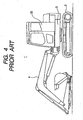
- Fig. 4 is a side view of a rear-end small-turn type power shovel 1, an example of a construction machine on which the cab disclosed in the above patent publication is mounted.
- a turntable 3 swingably mounted on a traveling gear 2 is mounted with the cab 20.
- a front end portion of the turntable 3 is mounted a working machine 4.
- a rear portion of the cab 20 is made of a flat vertical wall.
- Fig. 5 is a sectioned side view of a mode of embodiment to which an operator's seat 40 is added of the cab 20 disclosed in the above patent publication
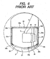
- Fig. 6 a plan view of the same embodiment.
- the cab 20 is fixed in the position on the turntable 3 which is offset from the center C of a swinging movement thereof 3, and an outer edge 8 (a broken line shows a turning circle of the slide door 30 being opened) of a turning circle of the slide door 30 being opened and closed stays within a turning radius R of the outer edge of the turntable 3.
- the cab 20 is provided with a total of five support posts 34a, 34b, 34c, 34d, 34e in the four left and right corners thereof and at an intermediate section of the portion thereof which is on the side of the slide door 30.
- an operator's seat 40 having a back 41 against which the back of an operator can be reclined is provided.
- flat vertical rear glass 24a is provided in the rear portion 24 of the cab 30, so that a clearance M between the back 41 of the operator's seat 40 and the rear glass 24a is narrow.
- the clearance M is really too narrow to place, for example, a tool box therein, and proves inconvenient.
- a reclining angle ⁇ cannot be set large, and an operator therefore cannot take a break in a comfortable posture during a rest period.
- JP 07 216936 A discloses a drive cabin arranged on a circular revolving stand in a state that a side wall is formed in an arcuate shape as seen from a plane along the peripheral edge part of the circular revolving stand 3 throughout a front part, a lateral outer part, and a rear part.
- a slide door in the range, extending from the front part to the front side part of the lateral outer part, of the side wall of the driver's cabin is mounted slidably releasably to a rear along the peripheral edge part of the circular revolving stand.
- EP-A-1190939 discloses a cab for an agricultural vehicle having front and rear corners and two rear fenders arranged one on each side at the rear of the cab.
- the cab comprises a frame that includes two rear support members.
- the rear support members have lower portions disposed at the back of the cab between the two fenders and upper portions 14c disposed above the fenders and offset laterally outwards from the lower portions.
- the present invention has been made with the inventor's attention paid to these problems, and aims at providing a slide door-carrying cab capable of having an outer side portion of the cab stay within a turning radius of an outer side portion of a turntable, and securing a sufficient space between a rear portion of the cab and a back of an operator's seat, and very comfortable for an operator to work and rest therein.
- the present invention provides a slide door-carrying cab for a construction machine according to claim 1.
- the rear side portion of the cab stays within the turning radius of the outer edge portion of the turntable, and is made of rear glass having an outwardly bulging curved surface. Therefore, there is not a fear of causing the cab to contact an outside obstacle when the turntable is swung. Moreover, a clearance between the back of the operator's seat and the rear side portion of the cab can be enlarged, so that it becomes possible to secure a storeroom-forming space sufficiently, increase the seat back reclining angle, and thereby improve the operator's comfort in the cab when he works and rests in the cab. Since the cab has curved surfaces, the external appearance thereof becomes excellent.
- the radius of curvature of the rear curved glass may be set equal to that of the side curved glass provided at the rear section of the curvedsurface-carrying outer side portion.
- the same mold can be used when the side curved glass and rear curved glass are molded, so that the cost can be reduced to a lower level.
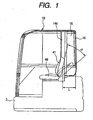
- a cab 10 is provided in the position on a turntable 3 which is offset from the center C of a swinging movement thereof.
- An outer side portion 11 constituting a side wall surface of the cab 10 is made so as to have an outwardly bulging curved surface.
- a slide door 12 opened and closed as the door is moved slidingly along the curved surface is provided at a front section of the outer side portion 11, and a rear wall surface portion at a rear section of the same.
- An outer edge (a broken line shows the slide door 12 in an opened state) of an orbit of opening and closing movements of the slide door 12 is adapted to stay on the inner side of a turning radius R of an outer edge portion of the turntable 3.
- support posts 14a, 14b are provided, and, at a front end part of the rear wall surface section of the outer side portion 11, a support post 14c.
- a support post 14d is provided, and, at a rear section of the support post 14d, flat glass 15 is fixed.
- the cab 10 is provided at a rear portion thereof with outwardly bulging two-dimensionally curved rear glass 16, an outer edge of which is adapted to stay on the inner side of the turning radius R of the outer edge portion of the upper turntable 3.
- the outer side portion 11 is provided at the rear wall surface section thereof with two-dimensionally curved glass 17.
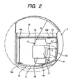
- the radius of curvature A1 of the rear curved glass 16 is equal to that A2 of the side curved glass 17.
- the contact portions of the flat glass 15 and side curved glass 17 and those of the rear curved glass 16 are bonded together and sealed with, for example, a silicone agent.
- the cab 10 is provided therein with an operator's seat 40 having a back 41 capable of being reclined.
- a clearance L between the back 41 and rear curved glass 16 can be set larger than that M in a related art cab since the rear curved glass 16 is bent outward. Therefore, the reclining angle ⁇ of the back can be set larger than that ⁇ thereof in the related art cab.
- the outwardly bulging rear curved glass 16 is provided on the outer side of the rear portion of the cab 10 so that the glass 16 stays within the turning radius of the outer edge portion of the upper turntable 3. Accordingly, there is not a fear of causing the rear curved glass 16 to contact an outside obstacle during a swinging movement of the turntable 3. Since the clearance between the back 41 of the operator's seat 40 and rear curved glass 16 can be set larger than that between the corresponding parts of the related art cab, a space in which, for example, a tool box is placed can be secured sufficiently in the clearance.
- the angle at which the operator's seat 40 is reclined becomes larger than that at which the operator's seat in the related art cab is reclined, so that the operator can take a break in a comfortable posture during a rest period. This enables the operator's comfort in the cab when he works and rests therein to be improved.
- the rear visual range is widened.
- the external appearance of the cab is improved since the glass in the rear portion thereof is made curvilinearly.
- the same mold can be used in common with these glass during the manufacturing thereof, and this enables the cost to be reduced.
Landscapes
- Engineering & Computer Science (AREA)
- Mechanical Engineering (AREA)
- Mining & Mineral Resources (AREA)
- Civil Engineering (AREA)
- General Engineering & Computer Science (AREA)
- Structural Engineering (AREA)
- Chemical & Material Sciences (AREA)
- Combustion & Propulsion (AREA)
- Transportation (AREA)
- Body Structure For Vehicles (AREA)
- Component Parts Of Construction Machinery (AREA)
- Window Of Vehicle (AREA)
Claims (2)
- Schiebetür-Führerkabine für eine Baumaschine,
wobei die Kabine (10) an einer Position bereitgestellt ist, die zum Zentrum einer Schwenkbewegung einer Drehplattform (3) versetzt ist, die schwenkbar auf einem Fahruntersatz (2) montiert ist,
wobei die Kabine (10) aufweist:einen inneren seitlichen Abschnitt (13),einen äußeren seitlichen Abschnitt (11) sowie einen hinteren Abschnitt, von denen jeder eine gekrümmte Fläche an einer Außenumfangseite der Drehplattform (3) hat, derart dass jede der gekrümmten Flächen nach außen gewölbt ist, undeine Schiebetür (12), die am äußeren seitlichen Abschnitt (11) bereitgestellt ist, derart dass die Schiebetür (12) geöffnet und geschlossen wird, wenn die Schiebtür (12) entlang der gekrümmten Fläche des äußeren seitlichen Abschnitts (11) schiebebewegt wird, wobei der Außenrand der Laufbahn der Öffnungs- und Schließbewegung der Schiebetür (12) innerhalb des Drehradius des Außenrandabschnitts der Drehplattform (3) liegt,wobei der äußere seitliche Abschnitt (11) an einem hinteren Abschnitt davon mit einer gekrümmten seitlichen Fensterscheibe (17) ausgestattet ist,wobei der hintere Abschnitt aus einer gekrümmten hinteren Fensterscheibe (16) gemacht ist, die innerhalb des Drehradius liegt und die eine gekrümmte nach außen gewölbte Fläche hat,wobei Stützpfosten (14a, 14b) auf der linken und der rechten Seite eines vorderen Endabschnitts der Kabine (10) bereitgestellt sind, undwobei ein Stützpfosten (14c) an einem vorderen Endteil des hinteren Abschnitts des äußeren seitlichen Abschnitts (11) bereitgestellt ist, ein Stützpfosten (14d) an einem Längsmittelabschnitt des inneren seitlichen Abschnitts (13) bereitgestellt ist und in dem linken hinteren und dem rechten hinteren Eckabschnitt der Kabine (10) keine Stützpfosten bereitgestellt sind, sodass der hintere Sichtbereich erweitert ist. - Schiebetür-Führerkabine gemäß Anspruch 1, wobei der Radius der Krümmung der hinteren gekrümmten Fensterscheibe (16) gleich jenem der gekrümmten seitlichen Fensterscheibe (17) gesetzt ist, die im hinteren Abschnitt des äußeren seitlichen Abschnitts (11) bereitgestellt ist.
Applications Claiming Priority (2)
| Application Number | Priority Date | Filing Date | Title |
|---|---|---|---|
| JP2003103292A JP4404567B2 (ja) | 2003-04-07 | 2003-04-07 | スライドドアを有するキャブの構造 |
| JP2003103292 | 2003-04-07 |
Publications (3)
| Publication Number | Publication Date |
|---|---|
| EP1466767A2 EP1466767A2 (de) | 2004-10-13 |
| EP1466767A3 EP1466767A3 (de) | 2008-09-17 |
| EP1466767B1 true EP1466767B1 (de) | 2011-05-18 |
Family
ID=32866710
Family Applications (1)
| Application Number | Title | Priority Date | Filing Date |
|---|---|---|---|
| EP04007846A Expired - Lifetime EP1466767B1 (de) | 2003-04-07 | 2004-03-31 | Kabine mit Schiebetür für eine Baumaschine |
Country Status (4)
| Country | Link |
|---|---|
| US (2) | US20040217629A1 (de) |
| EP (1) | EP1466767B1 (de) |
| JP (1) | JP4404567B2 (de) |
| CN (1) | CN100572694C (de) |
Families Citing this family (6)
| Publication number | Priority date | Publication date | Assignee | Title |
|---|---|---|---|---|
| US6942282B1 (en) * | 2004-06-17 | 2005-09-13 | Cnh America Llc | Wrap-around cab control layout for bale wagon |
| JP4594884B2 (ja) * | 2006-03-13 | 2010-12-08 | 株式会社クボタ | 作業車のキャビン構造 |
| FR2899197B1 (fr) * | 2006-04-04 | 2009-03-20 | Jean Naud | Habitacle de vehicule a ouverture adaptable |
| US10596989B2 (en) | 2016-05-12 | 2020-03-24 | Westinghouse Air Brake Technologies Corporation | Driver's barrier door with powered window |
| JP6971773B2 (ja) * | 2017-10-20 | 2021-11-24 | 株式会社小松製作所 | 作業車両のキャブ、作業車両およびホイールローダ |
| US11813930B2 (en) | 2018-05-31 | 2023-11-14 | Oshkosh Corporation | Vehicle door and window arrangement |
Family Cites Families (12)
| Publication number | Priority date | Publication date | Assignee | Title |
|---|---|---|---|---|
| US5080425A (en) * | 1990-05-18 | 1992-01-14 | Austin Terry R | Window accessory for a vehicle |
| JPH0612556U (ja) * | 1992-07-21 | 1994-02-18 | 株式会社小松製作所 | 建設機械の運転室 |
| JP2930853B2 (ja) * | 1994-02-09 | 1999-08-09 | 株式会社クボタ | 小型バックホウの運転部 |
| US5564774A (en) * | 1994-05-05 | 1996-10-15 | Kabushiki Kaisha Komatsu Seisakusho | Operation room of construction machine |
| JP3562875B2 (ja) * | 1995-06-15 | 2004-09-08 | コベルコ建機株式会社 | 建設機械用キャブの構造 |
| JPH10168941A (ja) * | 1996-12-11 | 1998-06-23 | Hitachi Constr Mach Co Ltd | 運転室付き作業機 |
| JP3934221B2 (ja) * | 1997-09-26 | 2007-06-20 | 株式会社クボタ | トラクタのキャビン |
| CN1098954C (zh) * | 1998-05-26 | 2003-01-15 | 日立建机株式会社 | 建筑机械用驾驶室 |
| JP3523792B2 (ja) * | 1998-09-25 | 2004-04-26 | 株式会社クボタ | キャビンの骨組構造 |
| DE19853536B4 (de) * | 1998-11-20 | 2004-09-09 | Jungheinrich Ag | Kabine für Frontsitz-Flurförderzeuge |
| JP4067242B2 (ja) * | 1999-08-09 | 2008-03-26 | 株式会社小松製作所 | 建設機械のキャブと同キャブを設置した建設機械 |
| GB2367038A (en) * | 2000-09-20 | 2002-03-27 | New Holland Uk Ltd | Cab for an agricultural vehicle |
-
2003
- 2003-04-07 JP JP2003103292A patent/JP4404567B2/ja not_active Expired - Fee Related
-
2004
- 2004-03-23 US US10/806,408 patent/US20040217629A1/en not_active Abandoned
- 2004-03-26 CN CNB2004100387612A patent/CN100572694C/zh not_active Expired - Fee Related
- 2004-03-31 EP EP04007846A patent/EP1466767B1/de not_active Expired - Lifetime
-
2006
- 2006-01-05 US US11/325,409 patent/US7517007B2/en not_active Expired - Fee Related
Also Published As
| Publication number | Publication date |
|---|---|
| JP4404567B2 (ja) | 2010-01-27 |
| US7517007B2 (en) | 2009-04-14 |
| JP2004306793A (ja) | 2004-11-04 |
| CN1538010A (zh) | 2004-10-20 |
| CN100572694C (zh) | 2009-12-23 |
| US20060175870A1 (en) | 2006-08-10 |
| US20040217629A1 (en) | 2004-11-04 |
| EP1466767A2 (de) | 2004-10-13 |
| EP1466767A3 (de) | 2008-09-17 |
Similar Documents
| Publication | Publication Date | Title |
|---|---|---|
| JP4226562B2 (ja) | 車体構造 | |
| US8052202B2 (en) | Vehicle frame for work vehicle and method for manufacturing same | |
| EP2679729B1 (de) | Baumaschine mit führerhausanordnung | |
| JP5639618B2 (ja) | テールゲート付き車両 | |
| WO2014006974A1 (ja) | テールゲート付き車両 | |
| EP1466767B1 (de) | Kabine mit Schiebetür für eine Baumaschine | |
| JP2021195039A (ja) | 乗物用シート | |
| JP3503223B2 (ja) | 自動車のドア構造 | |
| JP3766611B2 (ja) | トラクタ | |
| JP4108412B2 (ja) | 作業車両 | |
| JP2002347668A (ja) | 作業車の運転部構造 | |
| JPH11269928A (ja) | バックホー並びにバックホーのキャビン装置 | |
| JPH08834Y2 (ja) | コンバインの運転部構造 | |
| JPH0718700A (ja) | 作業機用キャノピー | |
| JPH11229439A (ja) | 建設機械のキャブ | |
| JP7122431B2 (ja) | キャビン | |
| JP4105912B2 (ja) | 車両用開閉装置の取付構造 | |
| JP3588858B2 (ja) | キャブの前窓構造 | |
| JP3535979B2 (ja) | 旋回作業機 | |
| JPH04339017A (ja) | 自動車のサイドドア構造 | |
| JP2583943Y2 (ja) | 建設機械用キャビン | |
| JP2773563B2 (ja) | フォークリフトのエンジンフード | |
| JP3535980B2 (ja) | 旋回作業機 | |
| JP3546872B2 (ja) | 移動車両のキャビン | |
| JP2584034Y2 (ja) | 超小旋回パワショベルのサイドガード装置 |
Legal Events
| Date | Code | Title | Description |
|---|---|---|---|
| PUAI | Public reference made under article 153(3) epc to a published international application that has entered the european phase |
Free format text: ORIGINAL CODE: 0009012 |
|
| AK | Designated contracting states |
Kind code of ref document: A2 Designated state(s): AT BE BG CH CY CZ DE DK EE ES FI FR GB GR HU IE IT LI LU MC NL PL PT RO SE SI SK TR |
|
| AX | Request for extension of the european patent |
Extension state: AL LT LV MK |
|
| 17P | Request for examination filed |
Effective date: 20060223 |
|
| PUAL | Search report despatched |
Free format text: ORIGINAL CODE: 0009013 |
|
| AK | Designated contracting states |
Kind code of ref document: A3 Designated state(s): AT BE BG CH CY CZ DE DK EE ES FI FR GB GR HU IE IT LI LU MC NL PL PT RO SE SI SK TR |
|
| AX | Request for extension of the european patent |
Extension state: AL LT LV MK |
|
| RIC1 | Information provided on ipc code assigned before grant |
Ipc: E02F 9/16 20060101ALI20080809BHEP Ipc: B62D 33/063 20060101ALI20080809BHEP Ipc: B62D 33/06 20060101ALI20080809BHEP Ipc: B60J 5/00 20060101AFI20040525BHEP |
|
| AKX | Designation fees paid |
Designated state(s): DE FR GB IT |
|
| 17Q | First examination report despatched |
Effective date: 20090702 |
|
| GRAP | Despatch of communication of intention to grant a patent |
Free format text: ORIGINAL CODE: EPIDOSNIGR1 |
|
| RTI1 | Title (correction) |
Free format text: SLIDE DOOR-CARRYING CAB FOR A CONSTRUCTION MACHINE |
|
| GRAS | Grant fee paid |
Free format text: ORIGINAL CODE: EPIDOSNIGR3 |
|
| GRAA | (expected) grant |
Free format text: ORIGINAL CODE: 0009210 |
|
| AK | Designated contracting states |
Kind code of ref document: B1 Designated state(s): DE FR GB IT |
|
| REG | Reference to a national code |
Ref country code: GB Ref legal event code: FG4D |
|
| REG | Reference to a national code |
Ref country code: DE Ref legal event code: R096 Ref document number: 602004032692 Country of ref document: DE Effective date: 20110630 |
|
| PLBE | No opposition filed within time limit |
Free format text: ORIGINAL CODE: 0009261 |
|
| STAA | Information on the status of an ep patent application or granted ep patent |
Free format text: STATUS: NO OPPOSITION FILED WITHIN TIME LIMIT |
|
| 26N | No opposition filed |
Effective date: 20120221 |
|
| PGFP | Annual fee paid to national office [announced via postgrant information from national office to epo] |
Ref country code: FR Payment date: 20120319 Year of fee payment: 9 |
|
| REG | Reference to a national code |
Ref country code: DE Ref legal event code: R097 Ref document number: 602004032692 Country of ref document: DE Effective date: 20120221 |
|
| PGFP | Annual fee paid to national office [announced via postgrant information from national office to epo] |
Ref country code: GB Payment date: 20120328 Year of fee payment: 9 Ref country code: IT Payment date: 20120320 Year of fee payment: 9 |
|
| GBPC | Gb: european patent ceased through non-payment of renewal fee |
Effective date: 20130331 |
|
| REG | Reference to a national code |
Ref country code: FR Ref legal event code: ST Effective date: 20131129 |
|
| PG25 | Lapsed in a contracting state [announced via postgrant information from national office to epo] |
Ref country code: FR Free format text: LAPSE BECAUSE OF NON-PAYMENT OF DUE FEES Effective date: 20130402 Ref country code: GB Free format text: LAPSE BECAUSE OF NON-PAYMENT OF DUE FEES Effective date: 20130331 |
|
| PG25 | Lapsed in a contracting state [announced via postgrant information from national office to epo] |
Ref country code: IT Free format text: LAPSE BECAUSE OF NON-PAYMENT OF DUE FEES Effective date: 20130331 |
|
| PGFP | Annual fee paid to national office [announced via postgrant information from national office to epo] |
Ref country code: DE Payment date: 20150324 Year of fee payment: 12 |
|
| REG | Reference to a national code |
Ref country code: DE Ref legal event code: R119 Ref document number: 602004032692 Country of ref document: DE |
|
| PG25 | Lapsed in a contracting state [announced via postgrant information from national office to epo] |
Ref country code: DE Free format text: LAPSE BECAUSE OF NON-PAYMENT OF DUE FEES Effective date: 20161001 |