EP1466774A2 - Fahrzeugantrieb - Google Patents
Fahrzeugantrieb Download PDFInfo
- Publication number
- EP1466774A2 EP1466774A2 EP04252115A EP04252115A EP1466774A2 EP 1466774 A2 EP1466774 A2 EP 1466774A2 EP 04252115 A EP04252115 A EP 04252115A EP 04252115 A EP04252115 A EP 04252115A EP 1466774 A2 EP1466774 A2 EP 1466774A2
- Authority
- EP
- European Patent Office
- Prior art keywords
- drive
- permanent magnet
- electric motors
- magnet electric
- drive apparatus
- Prior art date
- Legal status (The legal status is an assumption and is not a legal conclusion. Google has not performed a legal analysis and makes no representation as to the accuracy of the status listed.)
- Withdrawn
Links
Images


Classifications
-
- B—PERFORMING OPERATIONS; TRANSPORTING
- B60—VEHICLES IN GENERAL
- B60K—ARRANGEMENT OR MOUNTING OF PROPULSION UNITS OR OF TRANSMISSIONS IN VEHICLES; ARRANGEMENT OR MOUNTING OF PLURAL DIVERSE PRIME-MOVERS IN VEHICLES; AUXILIARY DRIVES FOR VEHICLES; INSTRUMENTATION OR DASHBOARDS FOR VEHICLES; ARRANGEMENTS IN CONNECTION WITH COOLING, AIR INTAKE, GAS EXHAUST OR FUEL SUPPLY OF PROPULSION UNITS IN VEHICLES
- B60K6/00—Arrangement or mounting of plural diverse prime-movers for mutual or common propulsion, e.g. hybrid propulsion systems comprising electric motors and internal combustion engines
- B60K6/20—Arrangement or mounting of plural diverse prime-movers for mutual or common propulsion, e.g. hybrid propulsion systems comprising electric motors and internal combustion engines the prime-movers consisting of electric motors and internal combustion engines, e.g. HEVs
- B60K6/22—Arrangement or mounting of plural diverse prime-movers for mutual or common propulsion, e.g. hybrid propulsion systems comprising electric motors and internal combustion engines the prime-movers consisting of electric motors and internal combustion engines, e.g. HEVs characterised by apparatus, components or means specially adapted for HEVs
- B60K6/26—Arrangement or mounting of plural diverse prime-movers for mutual or common propulsion, e.g. hybrid propulsion systems comprising electric motors and internal combustion engines the prime-movers consisting of electric motors and internal combustion engines, e.g. HEVs characterised by apparatus, components or means specially adapted for HEVs characterised by the motors or the generators
-
- B—PERFORMING OPERATIONS; TRANSPORTING
- B60—VEHICLES IN GENERAL
- B60K—ARRANGEMENT OR MOUNTING OF PROPULSION UNITS OR OF TRANSMISSIONS IN VEHICLES; ARRANGEMENT OR MOUNTING OF PLURAL DIVERSE PRIME-MOVERS IN VEHICLES; AUXILIARY DRIVES FOR VEHICLES; INSTRUMENTATION OR DASHBOARDS FOR VEHICLES; ARRANGEMENTS IN CONNECTION WITH COOLING, AIR INTAKE, GAS EXHAUST OR FUEL SUPPLY OF PROPULSION UNITS IN VEHICLES
- B60K17/00—Arrangement or mounting of transmissions in vehicles
- B60K17/34—Arrangement or mounting of transmissions in vehicles for driving both front and rear wheels, e.g. four wheel drive vehicles
- B60K17/356—Arrangement or mounting of transmissions in vehicles for driving both front and rear wheels, e.g. four wheel drive vehicles having fluid or electric motor, for driving one or more wheels
-
- B—PERFORMING OPERATIONS; TRANSPORTING
- B60—VEHICLES IN GENERAL
- B60K—ARRANGEMENT OR MOUNTING OF PROPULSION UNITS OR OF TRANSMISSIONS IN VEHICLES; ARRANGEMENT OR MOUNTING OF PLURAL DIVERSE PRIME-MOVERS IN VEHICLES; AUXILIARY DRIVES FOR VEHICLES; INSTRUMENTATION OR DASHBOARDS FOR VEHICLES; ARRANGEMENTS IN CONNECTION WITH COOLING, AIR INTAKE, GAS EXHAUST OR FUEL SUPPLY OF PROPULSION UNITS IN VEHICLES
- B60K6/00—Arrangement or mounting of plural diverse prime-movers for mutual or common propulsion, e.g. hybrid propulsion systems comprising electric motors and internal combustion engines
- B60K6/20—Arrangement or mounting of plural diverse prime-movers for mutual or common propulsion, e.g. hybrid propulsion systems comprising electric motors and internal combustion engines the prime-movers consisting of electric motors and internal combustion engines, e.g. HEVs
- B60K6/22—Arrangement or mounting of plural diverse prime-movers for mutual or common propulsion, e.g. hybrid propulsion systems comprising electric motors and internal combustion engines the prime-movers consisting of electric motors and internal combustion engines, e.g. HEVs characterised by apparatus, components or means specially adapted for HEVs
- B60K6/36—Arrangement or mounting of plural diverse prime-movers for mutual or common propulsion, e.g. hybrid propulsion systems comprising electric motors and internal combustion engines the prime-movers consisting of electric motors and internal combustion engines, e.g. HEVs characterised by apparatus, components or means specially adapted for HEVs characterised by the transmission gearings
-
- B—PERFORMING OPERATIONS; TRANSPORTING
- B60—VEHICLES IN GENERAL
- B60K—ARRANGEMENT OR MOUNTING OF PROPULSION UNITS OR OF TRANSMISSIONS IN VEHICLES; ARRANGEMENT OR MOUNTING OF PLURAL DIVERSE PRIME-MOVERS IN VEHICLES; AUXILIARY DRIVES FOR VEHICLES; INSTRUMENTATION OR DASHBOARDS FOR VEHICLES; ARRANGEMENTS IN CONNECTION WITH COOLING, AIR INTAKE, GAS EXHAUST OR FUEL SUPPLY OF PROPULSION UNITS IN VEHICLES
- B60K6/00—Arrangement or mounting of plural diverse prime-movers for mutual or common propulsion, e.g. hybrid propulsion systems comprising electric motors and internal combustion engines
- B60K6/20—Arrangement or mounting of plural diverse prime-movers for mutual or common propulsion, e.g. hybrid propulsion systems comprising electric motors and internal combustion engines the prime-movers consisting of electric motors and internal combustion engines, e.g. HEVs
- B60K6/22—Arrangement or mounting of plural diverse prime-movers for mutual or common propulsion, e.g. hybrid propulsion systems comprising electric motors and internal combustion engines the prime-movers consisting of electric motors and internal combustion engines, e.g. HEVs characterised by apparatus, components or means specially adapted for HEVs
- B60K6/40—Arrangement or mounting of plural diverse prime-movers for mutual or common propulsion, e.g. hybrid propulsion systems comprising electric motors and internal combustion engines the prime-movers consisting of electric motors and internal combustion engines, e.g. HEVs characterised by apparatus, components or means specially adapted for HEVs characterised by the assembly or relative disposition of components
-
- B—PERFORMING OPERATIONS; TRANSPORTING
- B60—VEHICLES IN GENERAL
- B60K—ARRANGEMENT OR MOUNTING OF PROPULSION UNITS OR OF TRANSMISSIONS IN VEHICLES; ARRANGEMENT OR MOUNTING OF PLURAL DIVERSE PRIME-MOVERS IN VEHICLES; AUXILIARY DRIVES FOR VEHICLES; INSTRUMENTATION OR DASHBOARDS FOR VEHICLES; ARRANGEMENTS IN CONNECTION WITH COOLING, AIR INTAKE, GAS EXHAUST OR FUEL SUPPLY OF PROPULSION UNITS IN VEHICLES
- B60K6/00—Arrangement or mounting of plural diverse prime-movers for mutual or common propulsion, e.g. hybrid propulsion systems comprising electric motors and internal combustion engines
- B60K6/20—Arrangement or mounting of plural diverse prime-movers for mutual or common propulsion, e.g. hybrid propulsion systems comprising electric motors and internal combustion engines the prime-movers consisting of electric motors and internal combustion engines, e.g. HEVs
- B60K6/42—Arrangement or mounting of plural diverse prime-movers for mutual or common propulsion, e.g. hybrid propulsion systems comprising electric motors and internal combustion engines the prime-movers consisting of electric motors and internal combustion engines, e.g. HEVs characterised by the architecture of the hybrid electric vehicle
- B60K6/44—Series-parallel type
-
- B—PERFORMING OPERATIONS; TRANSPORTING
- B60—VEHICLES IN GENERAL
- B60K—ARRANGEMENT OR MOUNTING OF PROPULSION UNITS OR OF TRANSMISSIONS IN VEHICLES; ARRANGEMENT OR MOUNTING OF PLURAL DIVERSE PRIME-MOVERS IN VEHICLES; AUXILIARY DRIVES FOR VEHICLES; INSTRUMENTATION OR DASHBOARDS FOR VEHICLES; ARRANGEMENTS IN CONNECTION WITH COOLING, AIR INTAKE, GAS EXHAUST OR FUEL SUPPLY OF PROPULSION UNITS IN VEHICLES
- B60K6/00—Arrangement or mounting of plural diverse prime-movers for mutual or common propulsion, e.g. hybrid propulsion systems comprising electric motors and internal combustion engines
- B60K6/20—Arrangement or mounting of plural diverse prime-movers for mutual or common propulsion, e.g. hybrid propulsion systems comprising electric motors and internal combustion engines the prime-movers consisting of electric motors and internal combustion engines, e.g. HEVs
- B60K6/50—Architecture of the driveline characterised by arrangement or kind of transmission units
- B60K6/52—Driving a plurality of drive axles, e.g. four-wheel drive
-
- B—PERFORMING OPERATIONS; TRANSPORTING
- B60—VEHICLES IN GENERAL
- B60K—ARRANGEMENT OR MOUNTING OF PROPULSION UNITS OR OF TRANSMISSIONS IN VEHICLES; ARRANGEMENT OR MOUNTING OF PLURAL DIVERSE PRIME-MOVERS IN VEHICLES; AUXILIARY DRIVES FOR VEHICLES; INSTRUMENTATION OR DASHBOARDS FOR VEHICLES; ARRANGEMENTS IN CONNECTION WITH COOLING, AIR INTAKE, GAS EXHAUST OR FUEL SUPPLY OF PROPULSION UNITS IN VEHICLES
- B60K6/00—Arrangement or mounting of plural diverse prime-movers for mutual or common propulsion, e.g. hybrid propulsion systems comprising electric motors and internal combustion engines
- B60K6/20—Arrangement or mounting of plural diverse prime-movers for mutual or common propulsion, e.g. hybrid propulsion systems comprising electric motors and internal combustion engines the prime-movers consisting of electric motors and internal combustion engines, e.g. HEVs
- B60K6/50—Architecture of the driveline characterised by arrangement or kind of transmission units
- B60K6/54—Transmission for changing ratio
-
- B—PERFORMING OPERATIONS; TRANSPORTING
- B60—VEHICLES IN GENERAL
- B60W—CONJOINT CONTROL OF VEHICLE SUB-UNITS OF DIFFERENT TYPE OR DIFFERENT FUNCTION; CONTROL SYSTEMS SPECIALLY ADAPTED FOR HYBRID VEHICLES; ROAD VEHICLE DRIVE CONTROL SYSTEMS FOR PURPOSES NOT RELATED TO THE CONTROL OF A PARTICULAR SUB-UNIT
- B60W10/00—Conjoint control of vehicle sub-units of different type or different function
- B60W10/04—Conjoint control of vehicle sub-units of different type or different function including control of propulsion units
- B60W10/08—Conjoint control of vehicle sub-units of different type or different function including control of propulsion units including control of electric propulsion units, e.g. motors or generators
-
- B—PERFORMING OPERATIONS; TRANSPORTING
- B60—VEHICLES IN GENERAL
- B60K—ARRANGEMENT OR MOUNTING OF PROPULSION UNITS OR OF TRANSMISSIONS IN VEHICLES; ARRANGEMENT OR MOUNTING OF PLURAL DIVERSE PRIME-MOVERS IN VEHICLES; AUXILIARY DRIVES FOR VEHICLES; INSTRUMENTATION OR DASHBOARDS FOR VEHICLES; ARRANGEMENTS IN CONNECTION WITH COOLING, AIR INTAKE, GAS EXHAUST OR FUEL SUPPLY OF PROPULSION UNITS IN VEHICLES
- B60K17/00—Arrangement or mounting of transmissions in vehicles
- B60K17/04—Arrangement or mounting of transmissions in vehicles characterised by arrangement, location or kind of gearing
- B60K17/043—Transmission unit disposed in on near the vehicle wheel, or between the differential gear unit and the wheel
-
- B—PERFORMING OPERATIONS; TRANSPORTING
- B60—VEHICLES IN GENERAL
- B60K—ARRANGEMENT OR MOUNTING OF PROPULSION UNITS OR OF TRANSMISSIONS IN VEHICLES; ARRANGEMENT OR MOUNTING OF PLURAL DIVERSE PRIME-MOVERS IN VEHICLES; AUXILIARY DRIVES FOR VEHICLES; INSTRUMENTATION OR DASHBOARDS FOR VEHICLES; ARRANGEMENTS IN CONNECTION WITH COOLING, AIR INTAKE, GAS EXHAUST OR FUEL SUPPLY OF PROPULSION UNITS IN VEHICLES
- B60K7/00—Disposition of motor in, or adjacent to, traction wheel
- B60K7/0007—Disposition of motor in, or adjacent to, traction wheel the motor being electric
-
- B—PERFORMING OPERATIONS; TRANSPORTING
- B60—VEHICLES IN GENERAL
- B60T—VEHICLE BRAKE CONTROL SYSTEMS OR PARTS THEREOF; BRAKE CONTROL SYSTEMS OR PARTS THEREOF, IN GENERAL; ARRANGEMENT OF BRAKING ELEMENTS ON VEHICLES IN GENERAL; PORTABLE DEVICES FOR PREVENTING UNWANTED MOVEMENT OF VEHICLES; VEHICLE MODIFICATIONS TO FACILITATE COOLING OF BRAKES
- B60T2270/00—Further aspects of brake control systems not otherwise provided for
- B60T2270/60—Regenerative braking
- B60T2270/603—ASR features related thereto
-
- Y—GENERAL TAGGING OF NEW TECHNOLOGICAL DEVELOPMENTS; GENERAL TAGGING OF CROSS-SECTIONAL TECHNOLOGIES SPANNING OVER SEVERAL SECTIONS OF THE IPC; TECHNICAL SUBJECTS COVERED BY FORMER USPC CROSS-REFERENCE ART COLLECTIONS [XRACs] AND DIGESTS
- Y02—TECHNOLOGIES OR APPLICATIONS FOR MITIGATION OR ADAPTATION AGAINST CLIMATE CHANGE
- Y02T—CLIMATE CHANGE MITIGATION TECHNOLOGIES RELATED TO TRANSPORTATION
- Y02T10/00—Road transport of goods or passengers
- Y02T10/10—Internal combustion engine [ICE] based vehicles
- Y02T10/40—Engine management systems
-
- Y—GENERAL TAGGING OF NEW TECHNOLOGICAL DEVELOPMENTS; GENERAL TAGGING OF CROSS-SECTIONAL TECHNOLOGIES SPANNING OVER SEVERAL SECTIONS OF THE IPC; TECHNICAL SUBJECTS COVERED BY FORMER USPC CROSS-REFERENCE ART COLLECTIONS [XRACs] AND DIGESTS
- Y02—TECHNOLOGIES OR APPLICATIONS FOR MITIGATION OR ADAPTATION AGAINST CLIMATE CHANGE
- Y02T—CLIMATE CHANGE MITIGATION TECHNOLOGIES RELATED TO TRANSPORTATION
- Y02T10/00—Road transport of goods or passengers
- Y02T10/60—Other road transportation technologies with climate change mitigation effect
- Y02T10/62—Hybrid vehicles
-
- Y—GENERAL TAGGING OF NEW TECHNOLOGICAL DEVELOPMENTS; GENERAL TAGGING OF CROSS-SECTIONAL TECHNOLOGIES SPANNING OVER SEVERAL SECTIONS OF THE IPC; TECHNICAL SUBJECTS COVERED BY FORMER USPC CROSS-REFERENCE ART COLLECTIONS [XRACs] AND DIGESTS
- Y10—TECHNICAL SUBJECTS COVERED BY FORMER USPC
- Y10S—TECHNICAL SUBJECTS COVERED BY FORMER USPC CROSS-REFERENCE ART COLLECTIONS [XRACs] AND DIGESTS
- Y10S903/00—Hybrid electric vehicles, HEVS
- Y10S903/902—Prime movers comprising electrical and internal combustion motors
- Y10S903/903—Prime movers comprising electrical and internal combustion motors having energy storing means, e.g. battery, capacitor
- Y10S903/904—Component specially adapted for hev
- Y10S903/906—Motor or generator
Definitions
- the present invention relates to a drive apparatus for a vehicle in which one pair of front or rear wheels are driven by a vehicle power train and the other pair of the front or rear wheels are driven by a pair of electric motors coupled to the other pair of the front or rear wheels.
- a space for accommodating a propeller shaft extending from a transmission in the front of the vehicle to the rear wheels is required. Therefore, in the conventional four-wheel drive vehicle, a propeller shaft tunnel is provided at a substantially widthwise center portion of a floor of the vehicle under the rear seats. In such a case, the floor is not level, and thus, comfort for the passengers is reduced.
- another type of conventional four-wheel drive vehicle includes an arrangement in which the driven wheels are disengaged with an electromagnetic clutch or the like when four-wheel drive is not required. In other words, in this type of the conventional four-wheel drive vehicle, the driven wheels are disengaged from the power train and driven by the drive wheels during two-wheel drive mode.
- hybrid 4WD vehicles hybrid four-wheel drive vehicles
- e-4WD systems disclose a hybrid 4WD vehicle in which the front wheels are driven by an engine and the rear wheels are driven by an electric motor such as a DC motor.
- the engine is also configured and arranged to drive a power generator at low to medium vehicle speeds.
- the hybrid 4WD vehicle disclosed in the above mentioned reference performs four-wheel drive using the engine and the DC motor with the power generated by the power generator when the vehicle starts moving or when the front wheels spin.
- front-wheel drive i.e., two-wheel drive
- front-wheel drive is performed using the engine alone.
- the drive force of the DC motor is transmitted to the differential gear of the rear wheels via a reduction gear and an electromagnetic clutch, and the drive force is then distributed to the left and right rear wheels by the differential gear.
- the torque-transmitting connections between the DC motor and the drive axles of the rear wheels i.e., the driven wheels
- the electromagnetic clutch disengaged by the electromagnetic clutch to prevent the DC motor from idling with the rotation of the driven wheels.
- the hybrid 4WD vehicle disclosed in the above mentioned reference most of the rear drive components such as the electrical wiring, the DC motor, the reduction gear, the electromagnetic clutch, the differential gear, and other components are disposed under the rear trunk. Therefore, the only difference between the hybrid 4WD vehicle disclosed in the above reference and a conventional front drive 2WD vehicle is that the height of the trunk bottom is slightly higher in the hybrid 4WD vehicle. Thus, with the hybrid 4WD vehicle disclosed in the above mentioned reference, there is almost no adverse affect on passengers' comfort in the rear seats. Accordingly, the hybrid 4WD vehicle disclosed in the above mentioned reference achieves four-wheel drive while the fuel consumption is kept lower than the conventional four-wheel drive vehicle in which the engine is the only drive source.
- the vehicle weight is reduced due to the absence of a propeller shaft. Moreover, there is no idling friction in the propeller shaft, differential gear, and the like when the vehicle is in the two-wheel drive mode.
- the hybrid 4WD vehicle disclosed in the above mentioned reference still utilizes a differential gear, an electromagnetic clutch, and other mechanical components for the wheels driven by the electric motor. Therefore, the weight of the vehicle cannot be reduced, which has been a hindrance to further improvement in fuel efficiency.
- the DC motor since the electric power is supplied to a rotor coil of the DC motor by brush contact, the DC motor has a relatively large amount of friction during idling. Therefore, it has been necessary to disengage the DC motor with the electromagnetic clutch to prevent the DC motor from idling with the slave rotation of the rear wheels during two wheel drive mode in which only the front wheels are driven in by the engine alone. Also, in the hybrid 4WD vehicle disclosed in the above mentioned reference, the differential gear has been indispensable for distributing the drive force of the DC motor to the left and right rear wheels.
- one object of the present invention is to provide a drive apparatus for a vehicle that achieves a vehicle that is lightweight, that has a simpler drive unit construction, and that suffers minimal idling-induced friction loss even when the driven wheels are driven by the drive wheels.
- a drive apparatus for a vehicle basically comprises a first drive unit and a second drive unit.
- the first drive unit includes at least a first non-permanent magnet electric motor configured and arranged to drive a first wheel, and a first reduction gear operatively coupled to the first non-permanent magnet electric motor to reduce speed of the first non-permanent magnet electric motor.
- the second drive unit including at least a second non-permanent magnet electric motor configured and arranged to drive a second wheel disposed on an opposite side of the vehicle from the first wheel, and a second reduction gear operatively coupled to the second non-permanent magnet electric motor to reduce speed of the second non-permanent magnet electric motor.
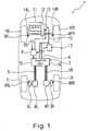
- Figure 1 is a simplified schematic view of an overall drive control system of a hybrid 4WD vehicle equipped with a drive apparatus in accordance with a first embodiment of the present invention
- Figure 2 is a schematic view of the drive apparatus illustrated in Figure 1 including a drive control system of left and right rear wheels of the hybrid 4WD vehicle in accordance with the first embodiment;
- Figure 3 is an axial cross-sectional view of an SR motor utilized in the drive apparatus in accordance with the first embodiment
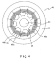
- Figure 4 is a partial cross-sectional view of the SR motor as viewed along a section line 4-4 in Figure 3;
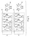
- Figure 5 is a schematic diagram of circuits included in an inverter unit utilized in the drive apparatus in accordance with the first embodiment
- Figure 6 is a simplified diagram illustrating a control of supplying drive current to the SR motor with respect to a rotation angle of a rotor, an inductance and a coil current in accordance with the first embodiment
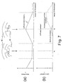
- Figure 7 is a simplified diagram illustrating a control of producing regenerative power by the SR motor with respect to the rotation angle of the rotor, the inductance and the coil current in accordance with the first embodiment
- Figure 8 is a schematic diagram of circuits included in the inverter unit utilized in the drive apparatus in accordance with the first embodiment
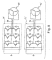
- Figure 9 is a schematic diagram of circuits included in an inverter unit utilized in a drive apparatus in accordance with a second embodiment of the present invention.
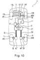
- Figure 10 is a simplified schematic view of an overall drive control system of a hybrid 4WD vehicle equipped with a drive apparatus in accordance with a third embodiment of the present invention.
- Figure 11 is a schematic view of the drive apparatus illustrated in Figure 10 including a drive control system of left and right rear wheels of the hybrid 4WD vehicle in accordance with the third embodiment of the present invention.
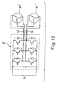
- Figure 12 is a schematic diagram of a circuit included in an inverter unit utilized in the drive apparatus in accordance with the third embodiment.
- FIG. 1 is a simplified schematic view of an overall drive control system of a hybrid four-wheel drive vehicle V equipped with the drive apparatus of the first embodiment.
- Figure 2 is a schematic view of the drive apparatus illustrated in Figure 1 including a drive control system of a first or left rear wheel 1L and a second or right rear wheel 1R of the hybrid four-wheel drive vehicle V.
- 4WD four-wheel drive
- 2WD two-wheel drive
- the vehicle V has an engine 11 that is a power-generating internal combustion engine or power source of a power train.
- the engine 11 is mechanically coupled to a power generator 13 for drive the power generating 13 to generate DC electric power.
- the engine 11 is also configured and arranged to drive a pair of left and right front wheels 10L and 10R using part of a power train that is a transmission 12 with an integrated with a clutch and a pair of left and right front wheel drive shafts 14L and 14R.
- the front wheels 10 and 10R are provided with a pair of left and right wheel speed sensors 8FL and 8FR for detecting the rotational speeds of the front wheels 10L and 10R, respectively.
- a pair of left and right reduction gears 3L and 3R, a pair of left and right non-permanent magnet electric motors 4L and 4R, and a pair of left and right brake discs 15L and 15R are housed substantially within the left and right rims 2L and 2R of the rear wheels 1L and 1R, respectively.
- the reduction gears 3L and 3R and the electric motors 4L and 4R are shown as being disposed outside of the rear wheels 1L and 1R in Figure 1 to better understand the connection relationship between these components for the illustration purpose only.
- the diameters of the reduction gears 3L and 3R and electric motors 4L and 4R are preferably small enough to fit in the rims 2L and 2R, respectively.
- the reduction gear 3L and the electric motor 4L are integrally assembled to constitute a first or left drive unit together with the brake disc 15L and a wheel speed sensor 8RL for detecting the rotational speed of the rear wheel 1L.
- the reduction gear 3R and the electric motor 4R are integrally assembled to constitute a second or right drive unit together with the brake disc 15R and a wheel speed sensor 8RR for detecting the rotational speed of the rear wheel 1R.
- each of the left and right drive units is incorporated in a corresponding one of the rims 2L and 2R.
- the wheel speed sensors 8RL and 8RR together preferably constitute a speed sensor unit that is configured to detect the speeds of the rear wheels 1L and 1R.
- Each of the reduction gears 3L and 3R is preferably a planetary reduction gear.
- An output shaft of the electric motors 4L, an input shaft and an output shaft of the reduction gear 3L, and a rotation shaft of the brake disc 15L are preferably arranged to be substantially coincident.
- an output shaft of the electric motors 4R, an input shaft and an output shaft of the reduction gear 3R, and a rotation shaft of the brake disc 15R are preferably arranged to be substantially coincident.
- the reduction gears 3L and 3R and the electric motors 4L and 4R are non-rotatably fixed to an axle (not shown) of the hybrid 4WD vehicle V so that the outputs from the reduction gears 3L and 3R are transmitted to the rims 2L and 2R via the brake discs 15L and 15R, respectively.
- the transmission gear ratio of each of the reduction gears 3L and 3R is preferably set such that speeds of the electric motors 4L and 4R are about 10,000 rpm when the speed of the hybrid 4WD vehicle V is about 50 km/hr.
- the transmission gear ratio of each of the reduction gears 3L and 3R is can be varied and is not limited to the above mentioned ratio.
- Each of the electric motors 4L and 4R is preferably a switched reluctance motor (hereinafter referred to as an SR motor). As seen in Figure 2, the electric motors 4L and 4R are preferably provided with left and right rotation angle sensors 25L and 25R, respectively.
- SR motor switched reluctance motor
- the power generator 13 is electrically coupled to a battery 17 via a power cable 16.
- the power generator 13 is configured and arranged to charge the battery 17.
- the DC current of the power generator 13 or the battery 17 is supplied to an inverter unit 7 via a power cable 6 connected to the power cable 16.
- the electric motors 4L and 4R are electrically connected to the battery 17 to change the battery 17 during braking as explained below.
- the inverter unit 7 preferably includes first and second inverters or left and right inverters 7L and 7R. Moreover, the inverters 7L and 7R of the inverter unit 7 are configured to separately supply electric power to the electric motors 4L and 4R via left and right power cables 5L and 5R, respectively.
- Figure 3 is an axial cross-sectional view along the rotational axis of the electric motor 4L
- Figure 4 is a transverse cross-sectional view of the electric motor 4L as viewed along the section line 4-4 in Figure 3.
- the electric motor 4L is preferably a so-called 12/8-pole type SR motor wherein a stator 46 has twelve salient poles 46a, and a rotor 45 has eight salient poles 45a.
- the stator 46 is formed by dividing each pole into twelve poles, and aligning and shrink-fitting the twelve poles around inside of a cylindrical steel frame 41, as shown in Figure 4.
- Each pole of the stator 46 comprises a base whose outer side constitutes an arc 1/12th of the inner circumference of the stator 46 and a plurality of thin magnetic steel plates with a thickness of about 0.5 mm or less (e.g., 0.35 mm or 0.2 mm) stacked in the axial direction of the electric motor 4L to form a substantially rectangular shape salient pole 46a extending inwardly from the base.
- a coil 46b is wounded around each of the salient poles 46a in a substantially rectangular shape in cross section as seen in Figure 4.
- the coils 46b are wound to form a U-phase coil, a v-phase coil and a W-phase coil that are intermittently subjected to the flow of current through their in a constant direction.
- the current in the coils 46b are selectively controlled for either acting as a motor or a generator as discussed below.
- the rotor 45 is formed by stacking a plurality of thin magnetic steel plates with a thickness of about 0.5 mm or less (e.g., 0.35 mm or 0.2 mm) in the axial direction that are perforated with a press into a shape having a central hole for accommodating a motor axle 43 and eight substantially rectangular protrusions extending radially.
- the magnetic steel plates are compressed and held on both sides by a pair of nonmagnetic thick steel plate end rings 45b, and shrink-fitted on the motor axle 43. Therefore, the rotor 45 is formed as a substantially solid component. Since the magnetic steel plates used to form the rotor 45 are relatively thin, iron loss during high-speed rotation is reduced. Moreover, loosening in the radial end portions of the magnetic steel plates during shrink-fitting and high-speed rotation can be prevented because the magnetic steel plates of the rotor 45 are held in the axial direction on both sides by the end rings 45b.
- both axial sides of the frame 41 of the electric motor 4L are covered by an end plate 42a through which the motor axle 43 passes, and an end plate 42b through which the motor axle 43 does not pass.
- the axial ends of the motor axle 43 are supported by a pair of ball bearings 44 disposed in bearing seats 47a and 47b that are provided on the end plates 42a and 42b, respectively.
- a pressure washer 49b is disposed on the bearing seat 47b for applying pressure to the ball bearings 44 inwardly in the axial direction.
- a washer 49a is disposed on the bearing seat 47a.
- each of the ball bearings 44 includes a plurality of bearing balls 44a, an outer ring or race 44b and an inner ring or race 44c.
- the bearing balls 44 are preferably made of silicon nitride ceramic, and the outer ring 44b and inner ring 44c are preferably made of high carbon chromium steel.
- An electric power supply bus bar 48 is disposed adjacent to the end plate 42b for the U, V, and W phases to the coils 46b.
- the bus bar 48 is connected to the coils 46b on each pole 46a of the stator 46.
- the rotation angle sensor 25L is coaxially disposed on the motor axle 43 adjacent to the end plate 42b side of the motor axle 43.
- the rotation angle sensor 25L is, for example, a resolver-type sensor.
- FIG. 5 is a schematic diagram switching of circuits of the inverters 7L and 7R of the inverter unit 7 used to selectively switch the conduction of the coils 46b in the electric motors 4L and 4R.
- the inverter 7R of the inverter unit 7 is preferably provided with a common inverter circuit for SR motors that basically comprises an input capacitor 51 for absorbing the surge current generated by switching, a plurality of diodes 52, and a plurality of switching elements 53 such as IGBT. Emitter and collector terminals of the switching elements 53, marked as UP and UN in Figure 5, are connected to terminals designated with the same symbols (UP and UN) in a U-phase coil 46b of the electric motor 4R shown in Figure 5. The V-phase and W-phase coils are constructed and connected in the same manner as the U-phase coil.
- a circuit of the inverter 7L has an identical structure as the circuit of the inverter 7R, and the emitter and collector terminals of the switching elements 53 of the inverter 7L are connected to corresponding coils 46b of the electric motor 4L as in the inverter 7R and the electric motor 4R.
- the inverters 7L and 7R of the inverter unit 7 are configured to control the DC current supplied via the power cable 6 and the flow of current through the U, V, and W phases of the coils 46b on the salient poles 46a of the stator 46 by switching the state of conduction of the switching elements 53 based on rotation angle signals detected by the rotation angle sensors 25L and 25R of the electric motors 4L and 4R, respectively. Therefore, in the first embodiment of the present invention, the inverters 7L and 7R are preferably configured to independently and separately control the rotations of the electric motors 4L and 4R, respectively.
- the inverter unit 7 is also configured and arranged to function as a regenerative brake by using the electric motors 4L and 4R as power generators, converting the AC current to DC current, and charging the battery 17 via the power cable 6.
- a 4WD control unit (4WD C/U) 9 is configured to coupled to the inverter unit 7 to control the inverters 7L and 7R. Also, the 4WD control unit 9 is coupled to the battery 17, and configured to detect the charging status of the battery 17. Then, the 4WD control unit 9 is configured to transmit signals for starting or stopping the power generator 13 depending on whether the hybrid 4WD vehicle V is operating in the 4WD or 2WD travel mode, and to control the power generator 13 accordingly.
- the 4WD control unit 9 preferably includes a microcomputer with a control program that controls the drive apparatus of the present invention as discussed below.
- the 4WD control unit 9 can also include other conventional components such as an input interface circuit, an output interface circuit, and storage devices such as a ROM (Read Only Memory) device and a RAM (Random Access Memory) device.
- the microcomputer of the 4WD control unit 9 is programmed to control the drive apparatus.
- the memory circuit stores processing results and control programs that are run by the processor circuit.
- the 4WD control unit 9 is operatively coupled to various sensors in a conventional manner as discussed below.
- the internal RAM of the 4WD control unit 9 stores statuses of operational flags and various control data.
- the 4WD control unit 9 is capable of selectively controlling any of the components of the control system in accordance with the control program. It will be apparent to those skilled in the art from this disclosure that the precise structure and algorithms for the 4WD control unit 9 can be any combination of hardware and software that will carry out the functions of the present invention. In other words, "means plus function" clauses as utilized in the specification and claims should include any structure or hardware and/or algorithm or software that can be utilized to carry out the function of the "means plus function” clause.
- the 4WD control unit 9 is preferably coupled to a brake pedal sensor 18, an accelerator pedal sensor 19, a steering angle sensor 20, an engine concentrated electronic control system/ control unit (ECCS C/U; hereinafter referred to as ECCS control unit) 21, a 4WD selector switch (4WD SW) 22, an anti-lock braking system control unit (ABS C/U; hereinafter referred to as ABS control unit) 23, an automatic transaxle control unit (A/T C/U; hereinafter referred to as A/T control unit) 24, and an indicator lamp 31.
- ECCS C/U engine concentrated electronic control system/ control unit
- ABS C/U anti-lock braking system control unit
- ABS control unit anti-lock braking system control unit
- A/T C/U automatic transaxle control unit
- A/T control unit automatic transaxle control unit
- the brake pedal sensor 18 is configured and arranged to detect when a brake pedal has been depressed, and transmit a braking signal to the 4WD control unit 9.
- the accelerator pedal sensor 19 is configured and arranged to detect when an accelerator has been depressed, and transmit a throttle position signal to the 4WD control unit 9.
- the steering angle sensor 20 is configured to detect the steering state of a steering wheel, and transmit a steering angle signal to the 4WD control unit 9.
- the 4WD selector switch 22 is used to select either one of the 4WD or 2WD travel mode and allow a driver to select the 2WD mode when the 4WD mode is unnecessary.
- the 4WD selector switch 22 is configured to transmit a selection state signal to the 4WD control unit 9.
- the ECCS control unit 21 is preferably a circuit configured to control an electronic throttle of the engine 11 and control both the output and speed of the engine 11 based on inputs of the throttle position signal (not shown) received from the accelerator pedal sensor 19 and an engine speed signal detected by an engine rotation sensor (not shown).
- the ECCS control unit 21 is configured to transmit the throttle position signal and the engine speed signal to the A/T control unit 24.
- the ECCS control unit 21 is configured to transmit the engine speed signal and throttle position signal to the 4WD control unit 9.
- the ABS control unit 23 is configured to determine whether the front wheels 10L and 10R and/or the rear wheels 1L and 1R are slipping based on the wheel speed signals received from the wheel speed sensors 8FL, 8FR, 8RL and 8RR coupled to the front wheels 10L and 10R and the rear wheels 1L and 1R, and transmit a slipping state signal to the 4WD control unit 9.
- the ABS control unit 23 is further configured to transmit the wheel speed signals for each of the front wheels 10L and 10R and the rear wheels 1L and 1R to the 4WD control unit 9.
- the A/T control unit 24 is preferably a circuit for controlling the transmission 12 based on signals such as the throttle position signal, the engine speed signal, the wheel speed signal received from the wheel speed sensors 8FL and 8FR coupled to the front wheels 10L and 10R, a selection range position selected by the driver with the selecting lever, and other vehicle operation signals.
- the A/T control unit 24 is configured to transmit the shift position signal of the transmission 12 to the 4WD control unit 9.
- the indicator lamp 31 is configured to display a warning signal if the 4WD control system is operating abnormally, and display whether the hybrid 4WD vehicle V is operating in the 4WD or 2WD travel mode.
- the 4WD control unit 9 is configured to place the inverter unit 7 in an electrically conducting state. Therefore, the inverters 7 are placed in a standby mode that enables the inverters 7L and 7R to drive the electric motors 4L and 4R, respectively, in response to control signals received from the 4WD control unit 9. In such case, the 4WD control unit 9 is configured to control the indicator lamp 31 to display that the 4WD travel mode has been selected.
- the 4WD control unit 9 is configured to monitor a charging status of the battery 17. If the battery 17 is insufficiently charged, the 4WD control unit 9 is configured to transmit a signal to the power generator 13 to start generation of power. Thus, the power generator 13 is driven by the engine 11 and generates electric power.
- the ECCS control unit 21 When the driver depresses the accelerator pedal, the ECCS control unit 21 is configured to adjust the electronic throttle.
- the A/T control unit 24 is configured to control the transmission 12 in accordance with the operation of the ECCS control unit 21, and drive the front wheels 10L and 10R by converting the output of the engine 11 into the target number of rotations and torque.
- the 4WD control unit 9 is configured to compute the vehicle speed based on the wheel speed signals for each of the front wheels 10L and 10R and the rear wheels 1L and 1R as received from the ABS control unit 23.
- the 4WD control unit 9 is further configured to compute the difference in rotation between the inside and outside rear wheels 1L and 1R (or 1R and 1L) based on the vehicle speed, the throttle position, the shift position, and the steering angle, and compute a target drive torque for each of the left and right rear wheels 1L and 1R.
- the 4WD control unit 9 is configured to transmit the control signals indicative of drive torques and direction of rotation to the inverters 7L and 7R.
- the inverters 7L and 7R are configured to switch controlling of the DC current from the battery 17 or the power generator 13 and supply the drive current to the electric motors 4L and 4R based on the control signals received from the 4WD control unit 9.
- the signals from the rotation angle sensors 25L and 25R are preferably fed back to the 4WD control unit 9 to separately control the electric motors 4L and 4R such that each of the rear wheels 1 L and 1R is provided with a corresponding target drive torque.
- the power supply or the current I to the U phase coils 46b are controlled as seen in the diagram of Figure 6. More specifically, the current begins to flow at an angle of rotation ⁇ 1 where the salient poles 46a of the stator 46 are aligned opposite the center of the troughs between adjacent salient poles 45a of the rotor 45. As seen in the diagram (a) of Figure 6, a maximum current is supplied between the angle of rotation ⁇ 1 and the angle of rotation ⁇ 2 when the salient poles 46a of the stator 46 are aligned opposite the salient poles 45a of the rotors so that a maximum inductive force is generated for the salient poles 45a of the rotors and salient poles 46a of the stators in a state of mutual attraction.
- the current I and inductive force are reduced to zero, thereby generating driving torque and preventing back torque (torque in an opposite direction) from being generated.
- the power supply of the V- and W-phase drive current is controlled in the substantially same manner as the U-phase drive current illustrated in Figure 6.
- the inverters 7L and 7R are configured to control the torque and the direction of rotation in the electric motors 4L and 4R. Accordingly, the inverters 7L and 7R, along with the electric motors 4L and 4R and the reduction gears 3L and 3R, are configured to distribute torque between the rear wheels 1L and 1R in the same manner as a conventional differential gear.
- the 4WD control unit 9 When the 4WD control unit 9 detects that the hybrid 4WD vehicle V is traveling at or above a prescribed speed (e.g., about 50 km/hr or more) the 4WD control unit 9 is configured to send a command to the inverters 7L and 7R to stop supplying power to the electric motors 4. Therefore, the rear wheels 1L and 1R are placed in a driven state in which the rear wheels 1L and 1R (i.e., the driven wheels) are driven by the forced rotation by the front wheels 1L and 1R, which are driven by the engine 11.
- the prescribed speed is set to about 50 km/hr so that the front wheels 10L and 10R (the engine-driven wheels) will not slip or skid on snow-covered roads or the like in the 2WD travel mode.
- the transmission gear ratio of the reduction gears 3L and 3R is preferably set to enable the electric motors 4L and 4R to rotate at about 10,000 rpm when the vehicle speed is about 50 km/hr. Therefore, the maximum speed of each of the electric motors 4L and 4R is about 40,000 rpm when the maximum vehicle speed is about 200 km/hr if the electric motors 4L and 4R were able to idle up to when the hybrid 4WD vehicle V is traveling at the maximum vehicle speed.
- the first embodiment of the present invention is configured to stop supplying the current to the electric motors 4L and 4R when the electric motors 4L and 4R are operating at a high speed such as in excess of 10,000 rpm (a vehicle speed of 50 km/hr or more).
- each of the ball bearings 44 of the electric motors 4L and 4R is preferably constituted as a silicon nitride ceramic ball bearing.
- each of the bearing balls 44a of the ball bearings has a relatively lower specific gravity, higher hardness, less thermal expansion, and a corrosion resistance that is remarkably higher than the ordinary bearing steel.
- the silicon nitride ceramic bearing ball 44a of the present invention preferably has a specific gravity of about 3.2 while the ordinary bearing steel usually has a specific gravity of about 7.8.
- the ceramic bearing ball 44a of the present invention preferably has a hardness of about 1500 HV while the ordinary bearing steel usually has a hardness of about 750 HV.
- the bearing balls 44a Since the bearing balls 44a has a relatively low specific gravity, which is one of the characteristics of such silicon nitride ceramic materials, the centrifugal force of the rolling elements (i.e., the ceramic bearing balls 44a in the present embodiment) is reduced and the temperature of the ball bearings 44 is prevented from increasing. Therefore, the working life of the ball bearings 44 used to support motor axle 43 that rotate at high speeds (i.e., about 10,000 to about 40,000 rpm) is improved. Moreover, since the ball bearings 44 has a relatively low thermal expansion, a temperature-induced variation of a space inside the ball bearings 44 is minimized, and vibration is prevented from occurring. Furthermore, an abrasion of the inner ring 44c and outer ring 44b, which is often a problem when the bearing balls 44a are made of bearing steel, is eliminated by using the ceramic bearing balls 44a.
- the 4WD control unit 9 is configured to detect when the hybrid 4WD vehicle V is decelerating or braking based on signals received from the brake pedal sensor 18 and accelerator pedal sensor 19 by detecting if the brake pedal is depressed to initiate related actions or if the accelerator pedal is released to coast.
- the 4WD control unit 9 determines the hybrid 4WD vehicle V is braking or decelerating when the driver has selected the 4WD travel mode and when the hybrid 4WD vehicle V is driving within a prescribed range of vehicle speeds
- the 4WD control unit 9 is configured to send a command to the power generator 13 and inverters 7L and 7R to generate power so that the inverters 7L and 7R function as regenerative brakes along with the power generator 13 and electric motors 4L and 4R.
- the DC current thus generated by the regenerative brake is charged in the battery 17.
- the prescribed range of the vehicle speeds within which the electric motors 4L and 4R (i.e., the SR motors) are configured to function as regenerative brakes is preferably set to a range of vehicle speeds exceeding 50 km/hr which is about the maximum vehicle speed up to which the drive current is supplied to the electric motors 4L and 4R.
- the power can be generated at high rotations that exceed the rotational drive speed.
- Regenerative energy is produced in proportion to the amount of energy supplied to the coils 46b.
- a diagram (a) of Figure 7 shows the change in inductance L of the U-phase coils 46b with respect to the angle of rotation ⁇ .
- a diagram (b) of Figure 7 shows the current supplied to the U-phase coils 46b, and the regenerative electric current produced, as a function of the angle of rotation ⁇ .
- the electrical fields are produced in the coils 46b when the salient poles 45a of the rotor 45 and the salient poles 46a of the stator 46 are aligned opposite each other. These electrical fields create a back torque that acts to prevent the salient poles 45a of the rotor 45 and the salient 46a of the stator 46 from moving further apart, and generate regenerative power.
- the 4WD control unit 9 is configured to control the supply of electric current to the U-phase coils 46b so that the electrical fields in the coils 46b increase within a range that does not exceed the withstand voltage of the inverters 7L and 7R. Accordingly, the regenerative power is generated that yields a regenerative electric current as illustrated by a dotted line in the diagram (b) of Figure 7.
- the 4WD control unit 9 is configured to control the supply of the V- and W-phase regenerative power in the substantially same manner as the supply of the U-phase regenerative power as illustrated in Figure 7.
- the 4WD control unit 9 is configured to place the inverter unit 7 including the inverters 7L and 7R in a non-electrically conducting state. In such case, the 4WD control unit 9 is configured to control the indicator lamp 31 to display that the 2WD mode has been selected.
- the hybrid 4WD vehicle V then functions as a conventional 2WD front drive vehicle.
- the 4WD control unit 9 of the first embodiment preferably constitutes a driven wheel drive controller.
- the front wheels 10L and 10R in the first embodiment correspond to primary driving wheels and the rear wheels 1L and 1R correspond to the driven wheels.
- the first embodiment of the present invention basically comprises a 4WD system in which each of the rear wheels 1L and 1R that are not driven by the engine 11 is coupled to the drive unit comprising the brake discs 15L or 15R, the reduction gears 3L or 3R, and the electric motors 4L or 4R.
- the drive unit is substantially housed within the rims 2L or 2R of the left or right rear wheels 1L and 1R.
- the drive unit has neither an electromagnetic clutch nor a differential gear for the rear wheels 1L and 1R. Accordingly, the overall weight of the 4WD system can be reduced, and fuel efficiency is improved.
- the electric motors 4L and 4R utilize the SR motors that are not furnished with a permanent magnet. Accordingly no back torque will be produced by a magnetic field as long as no electrical power is supplied to the electric motors 4L and 4R. Therefore, only loss of energy due to forced rotation of the rear wheels 1L and 1R is caused by an inertia resulting from the weight of the rotors 45 during acceleration and deceleration and the friction resistance of the ball bearings 44. Therefore, the loss of energy due to forced rotation of the rear wheels 1L and 1R is kept very low
- the ball bearings 44 of the electric motors 4L and 4R utilize the ceramic bearing balls 44a that are suited to high speeds of up to 200 km/hr, which is in excess of the range of vehicle speed (i.e., 0 to about 50 km/hr) permitted for the drive current to be supplied to the electric motors 4L and 4R. Therefore, when the rotors 45 of the electric motors 4L and 4R are rotated in accordance with the slave rotation of the rear wheels 1L and 1R, rapid forced rotation up to about 40,000 rpm can be externally induced.
- the rotors 45 of the electric motors 4L and 4R are preferably made lighter in weight than those of DC motors with armatures.
- the rotors 45 of the electric motors 4L and 4R have relatively rigid structures, the forced rotation in the electric motors 4L and 4R are possible up to the maximum speed of the hybrid 4WD vehicle V and any mechanical loss due to the centrifugal forces acting on the rotors 45 during high-speed operation can be eliminated.
- the diameter of the rotors 45 can be made larger than in other type of electric motors, even though the electric motors 4L and 4R are capable of forced rotation at high speeds.
- a large amount of torque can be produced from the electric motors 4L and 4R that are compact enough to be housed within the rims 2L and 2R, respectively.
- any friction caused by brush contact during idling such as that which occurs in DC motors is eliminated. Therefore, any adverse effect on fuel efficiency that accompanies the increased friction produced during periods of idling at high speeds can be minimized. Consequently, the drive apparatus having a relatively simple structure is obtained without having to provide an electromagnetic clutch to the reduction gears 3L and 3R.
- the electric motors 4L and 4R are stopped when the vehicle speed reaches about 50 km/hr or higher.
- the reduction gear ratio of the reduction gears 3L and 3R are preferably set such that the speed of the electric motors is about 10,000 rpm when the vehicle speed is about 50 km/hr.
- a voltage that is higher than the induced voltage generated in the coils 46b of the electric motors 4L and 4R has to be impressed on the coils 46b.
- a power source having an appropriately higher voltage has to be used to impress the required voltage on the coils 46b.
- the withstand voltage of the inverters 7L and 7R has to be increased. Reducing the number of coil windings in the electric motors 4L and 4R is one possible alternative method that makes it possible to avoid substantially increasing the withstand voltage of the inverters 7L and 7R.
- the output current of the inverters 7L and 7R must be increased in such case in order to preserve the torque generated by the electric motors 4L and 4R during periods of low rotation.
- the electric motors 4L and 4R are driven up to about 10,000 rpm. Therefore, the inverters 7L and 7R and electric motors 4L and 4R can be designed for use at lower voltages in comparison with designs of the inverters and electric motors in which electric motors are driven by the inverters up to even higher speeds. Therefore, in the first embodiment of the present invention, the number of coil windings in the electric motors 4L and 4R do not need to be reduced, and the output current of the inverters 7L and 7R can be lowered. Accordingly, the structure of the inverters 7L and 7R and electric motors 4L and 4R are simplified to achieve more compact, lightweight, and inexpensive structure.
- SR motors are used for the electric motors 4L and 4R, regenerative power is obtained by supplying electric power with a certain timing so that the priming current is supplied to the coils 46b within the withstand voltage of the inverters 7L and 7R, even when the number of rotations exceeds about 10,000 rpm which is the maximum speed of the electric motors 4L and 4R for controlling the supply of power required to drive the rear wheels 1L and 1R.
- each of the left and right rear wheels 1L and 1R is coupled to the electric motors 4L or 4R. Therefore, each of the electric motors 4L and 4R are configured to produce half the output generated by a single motor when the left and right wheels were provided with the single motor. Accordingly, the electric motors 4L and 4R can be made compact. Moreover, a compact configuration of the electric motors 4L and 4R is obtained also by having the drive unit (i.e., a single integrated unit comprising the electric motor 4L or 4R, the reduction gear 3L or 3R, and the brake disc 15L or 15R) substantially housed within the rim 2L or 2R.
- the drive unit i.e., a single integrated unit comprising the electric motor 4L or 4R, the reduction gear 3L or 3R, and the brake disc 15L or 15R
- the drive units for the rear wheels 1L and 1R are made to a compact configuration. Therefore, the tasks required to install the drive units for the rear wheels 1L and 1R on the axle for the rear wheels 1L and 1R can be performed in the same manner as the brake discs are mounted on the axle for the rear wheels when a front-drive 2WD vehicle is assembled. Therefore, in the present invention, there is less work to be performed in the assembly process comparing with a conventional hybrid 4WD vehicle or a conventional 4WD vehicle. Thus, manufacturing costs can be reduced.
- the hybrid 4WD vehicle V When the driver has selected the 4WD travel mode before the hybrid 4WD vehicle V is started, the hybrid 4WD vehicle V is configured and arranged to function as a 4WD vehicle at speeds ranging from a standing start to about 50 km/hr.
- the hybrid 4WD vehicle V is configured to reduce possibility of spinning when the vehicle starts off as a result of a suspension-induced temporary reduction in the grip of the front wheels 10L and 10R, which are the wheels driven by the engine 11. Since the rear wheels 1L and 1R are driven by the electric motors 4L and 4R, the wheel spin is alleviated, which allows the hybrid 4WD vehicle V to start off in a smooth manner.
- the inverters 7L and 7R of the inverter unit 7 can be constituted with an alternative structure as shown in Figure 8.
- the alternative structure of the inverter unit 7 includes an input capacitor 51' that is shared between the inverters 7L and 7R, instead of two input capacitors 51 for each of the inverters 7L and 7R as shown in Figure 5. Since the input capacitor 51' is shared between the inverters 7L and 7R in this alternative structure of the inverter unit 7, number of components can be reduced. Accordingly, the overall configuration of the inverter unit 7 can be made compact and lightweight.
- the structure of the SR motors used as the electric motors 4L and 4R is not limited to an inner rotor type as illustrated in Figures 3 and 4. Rather, an outer rotor type of the electric motor 4L and 4R can also be utilized.
- a differential gear between the rear wheels 1L and 1R can be eliminated.
- the weight of the hybrid 4WD vehicle V can be reduced because of a configuration wherein the drive unit comprises the electric motor 4L or 4R with no permanent magnet and the reduction gear 3L or 3R is coupled to each of the left and right driven wheels (the rear wheels 1L and 1R).
- the electric motors 4L and 4R are configured to drive the rear wheels 1L and 1R via the reduction gears 3L and 3R, respectively.
- the drive apparatus of the second embodiment is identical to the drive apparatus of the first embodiment, except that a pair of electric motors 4L' and 4R' utilize three-phase induction motors instead of the SR motors as in the first embodiment, and a pair of inverters 7L' and 7R' are substituted for the inverters 7L and 7R as seen in Figure 9. More specifically, each of the three-phase induction motors 4L' and 4R' (i.e., the three-phase induction motors) of the second embodiment is provided with a rotation speed sensor while the three-phase induction motors 4L and 4R (the SR motors) of the first embodiment are provided with the rotation angle sensors 25L and 25R, respectively.
- each of the inverters 7L' and 7R' is provided with a two-phase bridge inverter circuit and configured and arranged to supply electrical power to corresponding one of the three-phase induction motors 4L' and 4R' and control the rotation of the corresponding one of the three-phase induction motors 4L' and 4R'.
- the other structures and configurations of the drive apparatus of the second embodiment are basically identical to those of the first embodiment shown in Figures 1 and 2.
- a pair of integrated left and right drive units comprising the three-phase induction motors 4L' and 4R', the reduction gears 3L and 3R and the brake discs 15L and 15R, respectively, are housed within the rims 2L and 2R.
- the compact configuration of the drive unit for the rear wheels 1L and 1R can be obtained.
- the inverter unit 7 includes the inverters 7L' and 7R' individually used for the left and right drive units for the left and right rear wheels 1L and 1R respectively.
- the inverters 7L' and 7R' are preferably configured and arranged to drive the three-phase induction motors 4L' and 4R' up to about 10,000 rpm.
- the operations and the effects of the second embodiment are basically the same as the first embodiment.
- rotors in the three-phase induction motors 4L' and 4R' are made lighter than those in conventional DC motors, and the rigid structure of the rotors in the three-phase induction motors also enables the forced rotation of the three-phase induction motors 4L' and 4R' to extend up to the maximum speed of the hybrid 4WD vehicle V.
- a drive apparatus having a relatively simple structure can be obtained without requiring a differential gear, or having to provide an electromagnetic clutch to the reduction gears 3L and 3R.
- improved fuel efficiency can be obtained.
- the comfort of passengers is also increased in the rear seats of the hybrid 4WD vehicle V, and the need to reduce the capacity of the trunk of the hybrid 4WD vehicle V is avoided.
- the workload required for the assembly process of the hybrid 4WD vehicle V can be reduced, which contributes to lower manufacturing costs.
- the drive apparatus of the second embodiment is preferably configured and arranged such that the three-phase induction motors 4L' and 4R' are preferably driven up to about 10,000 rpm. Therefore, the inverters 7L' and 7R' and the three-phase induction motors 4L' and 4R' can be designed for use at low voltages, which allows the structures and configuration of the inverters 7L' and 7R' and the three-phase induction motors 4L' and 4R' to be simplified. Thus, the weight and manufacturing costs of the hybrid 4WD vehicle V can be reduced.
- Figure 10 is a simplified schematic view of an overall drive control system of the hybrid 4WD vehicle V equipped with the drive apparatus of the third embodiment.
- Figure 11 is a schematic view of the drive apparatus illustrated in Figure 10 including a drive control system of a left rear wheel 1L and a right rear wheel 1R of the hybrid 4WD vehicle V.
- Figure 12 is a schematic diagram of a circuit included in an inverter unit 27 utilized in the drive apparatus of the third embodiment.
- the electric motors 4L" and 4R" utilize three-phase induction motors without rotation speed sensors instead of the SR motors with the rotation speed sensors 25L and 25R as in the first embodiment.
- the inverter unit 27 is constituted as a conventional bridge inverter circuit for supplying electrical power to the three-phase induction motors 4L" and 4R" and controlling the rotation of the three-phase induction motors 4L” and 4R" as shown in Figure 12.
- the three-phase induction motors 4L” and 4R" are connected to the inverter unit 27 in parallel using the power cable 5L and 5R, respectively.
- the signals of the wheel rotation speed sensors 8RL and 8RR coupled to the rear wheels 1L and 1R from the ABS control unit 23 to a 4WD control unit 9' are used to be substituted with the motor speed signals to the inverter unit 27 that are used for the feedback control of the speed of the three-phase induction motors 4L" and 4R" by the 4WD control unit 9'.
- the 4WD control unit 9' is not configured to receive input signals from a steering angle sensor.
- the numbers of rotations of the three-phase induction motors 4L" and 4R" are determined by the inverter unit 27 based on the numbers of rotations of the rear wheels 1L and 1R with respect to the transmission gear ratio of the reduction gears 3L and 3R.
- An average number of rotations of the three-phase induction motors 4L” and 4R" is set as the number of rotations used for the feedback control of the inverter unit 27.
- the inverter unit 27 includes only one circuit that drives both of the left and right three-phase induction motors 4L" and 4R" using the same drive frequency.
- the 4WD control unit 9' is configured to compute the vehicle speed based on the wheel speed signals for the front wheels 10L and 10R and the rear wheels 1L and 1R as received from the ABS control unit 23.
- the 4WD control unit 9' is further configured to compute the target drive torque for the rear wheels 1L and 1R based on the vehicle speed, throttle position, and shift position. Then the 4WD control unit 9' is configured to transmit control signals for drive torque and direction of rotation of the three-phase induction motors 4L" and 4R" to the inverter unit 27.
- the inverter unit 27 is configured and arranged to convert the DC current received from the battery 17 or power generator 13 into the required three-phase AC current based on the control signals received from the 4WD control unit 9', and drive the three-phase induction motors 4L" and 4R".
- the torque of each of the three-phase induction motors 4L" and 4R" is substantially proportional to a spinning frequency, i.e., a difference between the drive frequency of the inverter unit 27 and a rotation frequency of the rotor of the induction motors 4L” or 4R" when the rotation speed of the three phase induction motors 4L” or 4R" is between the synchronous rotation speed and the rotation speed corresponding to a maximum torque.
- the slipping wheel rotates substantially synchronously with the drive frequency of the inverter unit 27 and the torque of the slipping wheel 1L or 1R will be decreased because the inverter unit 27 is configured and arranged to drive the three-phase induction motors 4L" and 4R" at the frequency of the average number of rotations that is substantially corresponding to the vehicle speed.
- the three-phase induction motors 4L" or 4R" of the rear wheels that are not idling or slipping holds the road surface, and a large amount of torque will be produced because the spinning frequency of the three-phase induction motors 4L" or 4R" of the non-slipping wheel 1L or 1R will be greater than that of the three-phase induction motors 4L" or 4R" of the slipping wheel 1L or 1R.
- a drive power will be generated in the three-phase induction motors 4L" or 4R" of the non-slipping wheel 1L or 1R.
- the drive power produced by the non-slipping wheel 1L or 1R enables the hybrid 4WD vehicle V to be controllably driven on the icy surface.
- the drive apparatus of the third embodiment is configured to provide substantially the same effects on the slipping wheel 1L and 1R as a conventional limited-slip differential, which is used with conventional differential gears for slipping wheels.
- the inverter unit 27 can be constituted with a single simple structure with an enlarged current capacity as shown in Figure 12, without having two inverters for each of the left and right rear wheels 1L and 1R as in the first and second embodiments.
- the inverter unit 27 Since the three-phase induction motors 4L" and 4R" are driven in parallel by the inverter unit 27 with a single circuit, the inverter unit 27 is enlarged as compared to the inverter unit 7 including the inverters 7L' and 7R' of the second embodiment that are configured to separately drive one of the three-phase induction motor 4L' and 4R'.
- the overall structure and configuration of the inverter unit 27 can be made more compact than the inverter unit 7' including two inverters 7L' and 7R'. Therefore, costs of manufacturing of the hybrid 4WD vehicle V can be reduced in the third embodiment than when two inverters are provided as in the first or second embodiment.
- the average value of the number of rotations obtained based on the signals from the wheel speed sensors 8RL and 8RR are used by the inverter unit 27 to control the number of rotations of the three-phase induction motors 4". Therefore, the three-phase induction motors 4L" and 4R" do not need to be provided with rotation speed sensors, and thus, costs can be reduced.
- the 4WD control units 9 or 9' is configured so that the electric motors 4L and 4L, 4L' and 4L', or 4L" and 4L” drive the rear wheels 1L and 1R up to a vehicle speed of about 50 km/hr when the 4WD travel mode is selected.
- the first, second and third embodiments can be configured and arranged to operate in the 4WD travel mode when wheel spin has been detected in the front wheel 10L and/or 10R, and in the 2WD travel mode when no wheel spin has been detected, based on the determination of the wheel spin state received from the ABS control unit 23.
- the target torque required to drive the electric motors 4L and 4R (the SR motors), 4L' and 4R', or 4L" and 4R" (the three-phase induction motors) is obtained by controlling the inverter unit 7, 7' or 27 and the amount of power generated by the power generator 13, according to calculations of the optimal torque required to drive the rear wheels 1L and 1R in 4WD travel mode.
- using a limited 4WD drive can prevent decreased fuel efficiency caused by the loss of heat generated by inverter unit 7, 7' or 27 and electric motors 4L and 4R (the SR motors), 4L' and 4R', or 4L" and 4R"(the three-phase induction motors) in situations where the 4WD drive mode has been employed when the 2WD mode would be sufficient.
- the present invention can also be utilized in circumstances where an engine is housed in a different location from that specified in the above explained preferred embodiments, or where primary drive wheels that are driven by an engine are positioned in a different location from that specified in the examples.
- the present invention can be adapted in a vehicle in which the primary drive wheels are a pair of rear wheels, and the electric motors are used to drive a pair of front wheels.
- the present invention can be adapted to a vehicle in which an electric motor is used as a power train that drives the primary drive wheels instead of an engine.
Landscapes
- Engineering & Computer Science (AREA)
- Chemical & Material Sciences (AREA)
- Combustion & Propulsion (AREA)
- Transportation (AREA)
- Mechanical Engineering (AREA)
- Electric Propulsion And Braking For Vehicles (AREA)
- Hybrid Electric Vehicles (AREA)
- Arrangement And Driving Of Transmission Devices (AREA)
- Arrangement Or Mounting Of Propulsion Units For Vehicles (AREA)
- Arrangement Of Transmissions (AREA)
Applications Claiming Priority (4)
| Application Number | Priority Date | Filing Date | Title |
|---|---|---|---|
| JP2003105647 | 2003-04-09 | ||
| JP2003105647 | 2003-04-09 | ||
| JP2004109043 | 2004-04-01 | ||
| JP2004109043A JP2004328991A (ja) | 2003-04-09 | 2004-04-01 | 車両の左右輪駆動装置 |
Publications (2)
| Publication Number | Publication Date |
|---|---|
| EP1466774A2 true EP1466774A2 (de) | 2004-10-13 |
| EP1466774A3 EP1466774A3 (de) | 2006-08-30 |
Family
ID=32871249
Family Applications (1)
| Application Number | Title | Priority Date | Filing Date |
|---|---|---|---|
| EP04252115A Withdrawn EP1466774A3 (de) | 2003-04-09 | 2004-04-08 | Fahrzeugantrieb |
Country Status (3)
| Country | Link |
|---|---|
| US (1) | US7195087B2 (de) |
| EP (1) | EP1466774A3 (de) |
| JP (1) | JP2004328991A (de) |
Cited By (10)
| Publication number | Priority date | Publication date | Assignee | Title |
|---|---|---|---|---|
| CN101966810A (zh) * | 2010-10-22 | 2011-02-09 | 浙江吉利汽车研究院有限公司 | 一种用于汽车的基于轮毂电机混联驱动系统 |
| CN102811879A (zh) * | 2010-03-25 | 2012-12-05 | Ntn株式会社 | 轮毂电动机驱动装置 |
| WO2013156979A3 (en) * | 2012-04-21 | 2014-07-24 | Debreceni Egyetem | Circuit arrangement and a method for controlling an ac drive system of an electric vehicle |
| EP2614979A4 (de) * | 2010-09-07 | 2014-08-06 | Ntn Toyo Bearing Co Ltd | Elektrofahrzeug mit radinternem motor |
| CN104875593A (zh) * | 2014-02-18 | 2015-09-02 | 李查启学 | 节能汽车及其盘型动力马达 |
| WO2016059356A3 (fr) * | 2014-10-17 | 2016-07-28 | Lohr Electromecanique | Véhicule hybride et procédé d'hybridation d'un véhicule |
| EP2199168B1 (de) * | 2008-12-16 | 2017-11-15 | Volvo Car Corporation | Autonomes Getriebe |
| EP2025570A4 (de) * | 2006-05-24 | 2018-01-24 | Toyota Jidosha Kabushiki Kaisha | Antriebskraftsteuervorrichtung für ein fahrzeug mit vierradantrieb |
| CN109789802A (zh) * | 2016-09-21 | 2019-05-21 | Ntn株式会社 | 车辆动力辅助系统 |
| EP2022662B1 (de) * | 2006-05-30 | 2019-08-21 | Toyota Jidosha Kabushiki Kaisha | Leistungsabgabegerät und fahrzeug damit |
Families Citing this family (67)
| Publication number | Priority date | Publication date | Assignee | Title |
|---|---|---|---|---|
| US7201244B2 (en) * | 2003-10-03 | 2007-04-10 | Letourneau, Inc. | Vehicle for materials handling and other industrial uses |
| US7017327B2 (en) * | 2003-12-10 | 2006-03-28 | Deere & Company | Hybrid electric tool carrier |
| JP2005297860A (ja) * | 2004-04-14 | 2005-10-27 | Toyota Motor Corp | 車両用電源装置 |
| US7378808B2 (en) * | 2004-05-25 | 2008-05-27 | Caterpillar Inc. | Electric drive system having DC bus voltage control |
| JP4581640B2 (ja) * | 2004-11-17 | 2010-11-17 | トヨタ自動車株式会社 | 車両駆動システムおよびそれを備える車両 |
| JP2006205925A (ja) * | 2005-01-28 | 2006-08-10 | Mitsubishi Motors Corp | ハイブリッド車両 |
| JP2006219082A (ja) * | 2005-02-14 | 2006-08-24 | Hitachi Ltd | 車両用回転電機システム |
| US7202625B2 (en) * | 2005-02-25 | 2007-04-10 | Caterpillar Inc | Multi-motor switched reluctance traction system |
| JP4513612B2 (ja) * | 2005-03-16 | 2010-07-28 | 日産自動車株式会社 | 車両のトルク配分制御装置 |
| EP1906523A4 (de) * | 2005-07-11 | 2012-10-10 | Hitachi Ltd | Steuerung für einen synchronmotor des feldwicklungstyps, elektrisches antriebssystem, elektrisches vierradfahrzeug und hybrid-automobil |
| JP4188348B2 (ja) * | 2005-08-10 | 2008-11-26 | 株式会社日立製作所 | 電動車両の走行制御装置および電動走行制御システム |
| KR100946352B1 (ko) | 2005-11-30 | 2010-03-08 | 도요타 지도샤(주) | 차륜독립구동식 차량의 구동력제어장치 |
| JP5063904B2 (ja) * | 2006-02-20 | 2012-10-31 | Ntn株式会社 | ハイブリッド自動車 |
| US7870925B2 (en) * | 2006-02-21 | 2011-01-18 | Ford Global Technologies, Llc | System and method for managing a powertrain in a vehicle |
| JP2007252153A (ja) * | 2006-03-20 | 2007-09-27 | Hitachi Ltd | 自動車の制御装置及び自動車 |
| WO2008005886A2 (en) * | 2006-07-07 | 2008-01-10 | Hydro-Gear Limited Partnership | Electronic steering control apparatus |
| US8950520B2 (en) | 2006-07-07 | 2015-02-10 | Hydro-Gear Limited Partnership | Front steering module for a zero turn radius vehicle |
| US20080169140A1 (en) * | 2007-01-16 | 2008-07-17 | Charles Hampton Perry | Machine for augmentation, storage, and conservation of vehicle motive energy |
| US20080223633A1 (en) * | 2007-03-14 | 2008-09-18 | Kim Richard J | Hybrid all-wheel drive train and vehicle |
| US20080236920A1 (en) * | 2007-03-27 | 2008-10-02 | Swindell Edward Leroy | All-electric motor car |
| JP4637136B2 (ja) * | 2007-05-23 | 2011-02-23 | 本田技研工業株式会社 | 動力装置 |
| US8027771B2 (en) * | 2007-09-13 | 2011-09-27 | GM Global Technology Operations LLC | Method and apparatus to monitor an output speed sensor during operation of an electro-mechanical transmission |
| US20090107749A1 (en) * | 2007-10-30 | 2009-04-30 | Textron Inc. | Closed Loop Traction System for Light-Weight Utility Vehicles |
| US8181904B1 (en) * | 2007-11-06 | 2012-05-22 | Borealis Technical Limited | Apparatus for facilitating tire valve stem access in self propelled aircraft undercarriage |
| US7854282B2 (en) * | 2007-12-10 | 2010-12-21 | International Humanities Center | Hybrid electric vehicle |
| US8360185B2 (en) * | 2008-02-14 | 2013-01-29 | Mitsuba Corporation | Hybrid electric automobile |
| JP2009214566A (ja) * | 2008-03-07 | 2009-09-24 | Hitachi Ltd | 4輪駆動車の駆動力制御装置 |
| US8091677B2 (en) * | 2008-03-27 | 2012-01-10 | GM Global Technology Operations LLC | System and method of differentiating rotational speed and torque between wheels of a hybrid vehicle |
| IT1392278B1 (it) * | 2008-12-18 | 2012-02-24 | Ferrari Spa | Veicolo stradale con propulsione ibrida |
| US20100163321A1 (en) * | 2008-12-30 | 2010-07-01 | Goff Sean K | Power converter module for a battery-operated vehicle |
| DE102010007632A1 (de) * | 2010-02-05 | 2011-08-11 | Dr. Ing. h.c. F. Porsche Aktiengesellschaft, 70435 | Hybridfahrzeug |
| US8875819B2 (en) * | 2010-03-01 | 2014-11-04 | Bae Systems Controls Inc. | Hybrid drive system for hybrid electric vehicles |
| US8544580B2 (en) * | 2010-05-18 | 2013-10-01 | The Hong Kong Polytechnic University | In-wheel switched reluctance motor drive |
| EP2389797B1 (de) * | 2010-05-27 | 2014-11-19 | Kanzaki Kokyukoki Mfg. Co., Ltd. | Elektrischer Rasenmäher |
| CN102259578A (zh) * | 2010-05-31 | 2011-11-30 | 金健 | 一种电力传动汽车 |
| JP5798815B2 (ja) * | 2010-07-02 | 2015-10-21 | 株式会社エムリンク | ホイールインモータ及び電動車両 |
| US9150093B2 (en) | 2010-07-02 | 2015-10-06 | M-Link Co., Ltd. | In-wheel motor and electrically driven vehicle |
| US20120067676A1 (en) * | 2010-09-17 | 2012-03-22 | Brammo, Inc. | Vehicle wheel braking system |
| JP2012157082A (ja) * | 2011-01-21 | 2012-08-16 | Nissan Motor Co Ltd | 車輪給電装置 |
| US8290657B2 (en) * | 2011-04-06 | 2012-10-16 | Ford Global Technologies | Direction determination for active park assist |
| US8666574B2 (en) * | 2011-04-21 | 2014-03-04 | Deere & Company | In-vehicle estimation of electric traction motor performance |
| KR101714084B1 (ko) * | 2011-11-23 | 2017-03-22 | 현대자동차주식회사 | 인휠 구동시스템 및 에이비에스 제동방법 |
| DE102011121819A1 (de) * | 2011-12-21 | 2013-06-27 | Conti Temic Microelectronic Gmbh | Antriebsstrang mit zwei Antriebsmaschinen für ein Fahrzeug und Verfahren zu dessen Betrieb |
| JP5965700B2 (ja) * | 2012-03-30 | 2016-08-10 | 本田技研工業株式会社 | 車両用駆動装置 |
| JP2014076715A (ja) * | 2012-10-10 | 2014-05-01 | Mitsubishi Motors Corp | ブレーキランプ制御装置 |
| JP6242863B2 (ja) * | 2013-04-02 | 2017-12-06 | パナソニック株式会社 | エンジン駆動車両に用いられる電動駆動装置 |
| CN105144555A (zh) * | 2013-04-12 | 2015-12-09 | 西门子公司 | 具有启动辅助的磁阻电机 |
| CN103303122A (zh) * | 2013-05-28 | 2013-09-18 | 福建工程学院 | 用于汽车的混合动力系统 |
| JP6186908B2 (ja) * | 2013-06-07 | 2017-08-30 | マツダ株式会社 | ハイブリッド車 |
| JP6197398B2 (ja) * | 2013-06-24 | 2017-09-20 | マツダ株式会社 | ハイブリッド車の制御装置 |
| JP6400297B2 (ja) * | 2014-01-29 | 2018-10-03 | Ntn株式会社 | インホイールモータ駆動装置 |
| US9914349B2 (en) | 2014-01-08 | 2018-03-13 | Ntn Corporation | In-wheel motor drive device |
| JP6217672B2 (ja) | 2015-03-06 | 2017-10-25 | 株式会社豊田中央研究所 | 駆動力配分装置 |
| JP2016203750A (ja) * | 2015-04-20 | 2016-12-08 | トヨタ自動車株式会社 | 車両制御装置 |
| DE102015006703A1 (de) * | 2015-05-23 | 2016-11-24 | Wabco Gmbh | Verfahren und Vorrichtung zum elektronischen Regeln einer Fahrzeugverzögerung in Abhängigkeit eines Differenzschlupfes zwischen zwei Fahrzeugachsen |
| WO2017006429A1 (ja) * | 2015-07-07 | 2017-01-12 | 日産自動車株式会社 | ホィール駆動装置の配設構造 |
| JP6286459B2 (ja) | 2016-02-12 | 2018-02-28 | 本田技研工業株式会社 | 車両 |
| JP6724479B2 (ja) * | 2016-03-30 | 2020-07-15 | 日本製鉄株式会社 | 無方向性電磁鋼板、モータコア、及び無方向性電磁鋼板の製造方法 |
| JP6724478B2 (ja) * | 2016-03-30 | 2020-07-15 | 日本製鉄株式会社 | 無方向性電磁鋼板、モータコア、及び無方向性電磁鋼板の製造方法 |
| CN105774504A (zh) * | 2016-05-13 | 2016-07-20 | 北京汽车研究总院有限公司 | 一种动力驱动系统及汽车 |
| CN106394230B (zh) * | 2016-09-09 | 2019-06-04 | 山东理工大学 | 一种油电混合多模式汽车驱动系统及控制方法 |
| CN106428196A (zh) * | 2016-11-16 | 2017-02-22 | 上海振华重工(集团)股份有限公司 | 车辆转向装置 |
| DE102016224199B4 (de) * | 2016-12-06 | 2026-03-05 | Bayerische Motoren Werke Aktiengesellschaft | Hybridfahrzeug |
| JP6851504B2 (ja) * | 2017-12-28 | 2021-03-31 | 三菱電機株式会社 | 電気車制御装置 |
| JP2018173173A (ja) * | 2018-06-15 | 2018-11-08 | Ntn株式会社 | インホイールモータ駆動装置 |
| CN116568546A (zh) * | 2020-12-07 | 2023-08-08 | 爱知制钢株式会社 | 用于电驱动移动对象的齿轮传动电机 |
| CN113043832B (zh) * | 2021-04-25 | 2023-03-10 | 湖南力行动力科技有限公司 | 小型轻量化双制动高功率重载电动轮总成 |
Citations (1)
| Publication number | Priority date | Publication date | Assignee | Title |
|---|---|---|---|---|
| JP2003105647A (ja) | 2001-09-28 | 2003-04-09 | Ueda Seni Kagaku Shinkokai | 原料繊維塊の密度調整機能を有するフライヤー式ツイストドラフト紡績機 |
Family Cites Families (24)
| Publication number | Priority date | Publication date | Assignee | Title |
|---|---|---|---|---|
| FR2158000A1 (de) * | 1971-10-30 | 1973-06-08 | Berkeley Stephens Hender | |
| US3970160A (en) * | 1973-11-06 | 1976-07-20 | William Nowick | Control means for electrically powered transportation means |
| JPS59102504U (ja) * | 1982-12-27 | 1984-07-10 | 株式会社シマノ | 自転車用ハブ |
| US5099186A (en) | 1990-12-31 | 1992-03-24 | General Motors Inc. | Integrated motor drive and recharge system |
| US5382854A (en) * | 1992-07-29 | 1995-01-17 | Kabushikikaisha Equos Research | Electrical motor drive apparatus with planetary gearing |
| US6089341A (en) * | 1993-05-15 | 2000-07-18 | Gingerich; Newton Roy | Electric powered vehicle |
| US5489831A (en) * | 1993-09-16 | 1996-02-06 | Honeywell Inc. | Pulse width modulating motor controller |
| GB9513914D0 (en) | 1995-07-07 | 1995-09-06 | Switched Reluctance Drives Ltd | Power circuit for reluctance machines |
| JP3460166B2 (ja) * | 1996-02-02 | 2003-10-27 | 株式会社シマノ | 自転車用フリーホイールの爪音消し機構 |
| JPH1067243A (ja) * | 1996-08-29 | 1998-03-10 | Honda Motor Co Ltd | 車両における補助駆動装置 |
| JP3447937B2 (ja) * | 1997-11-18 | 2003-09-16 | 本田技研工業株式会社 | ハイブリッド車両 |
| DE19847673A1 (de) * | 1998-10-15 | 2000-04-20 | Dt Swiss Ag | Nabe, insbesondere für Fahrräder u. dgl. |
| JP3449284B2 (ja) | 1999-03-16 | 2003-09-22 | 日産自動車株式会社 | 四輪駆動装置 |
| JP2001260836A (ja) * | 2000-03-23 | 2001-09-26 | Toyota Motor Corp | 車両用駆動力配分制御装置 |
| JP2002029824A (ja) * | 2000-07-21 | 2002-01-29 | Ngk Spark Plug Co Ltd | セラミックボール、ボールベアリング、ベアリング付きモータ、ハードディスク装置、ポリゴンスキャナ、及びセラミックボールの製造方法 |
| DE20013400U1 (de) * | 2000-08-03 | 2000-12-21 | Kun Teng Industry Co., Ltd., Ta-Ya Hsiang, Taichung | Naben-Kraftübertragungsmechanismus mit einem Dichtungselement |
| US6386644B2 (en) * | 2000-08-08 | 2002-05-14 | Kun Teng Industry Co., Ltd. | Bicycle hub provided with a seal member for preventing entrance of dust |
| JP4460145B2 (ja) * | 2000-08-30 | 2010-05-12 | 本田技研工業株式会社 | 電気自動車におけるインホイール変速機の制御装置 |
| JP3721973B2 (ja) * | 2000-09-28 | 2005-11-30 | 日産自動車株式会社 | 車両の操舵装置 |
| US6717281B1 (en) * | 2000-10-26 | 2004-04-06 | Dennis Brandon | Electric generator and motor drive system |
| US6573675B2 (en) | 2000-12-27 | 2003-06-03 | Transportation Techniques Llc | Method and apparatus for adaptive energy control of hybrid electric vehicle propulsion |
| US6622804B2 (en) * | 2001-01-19 | 2003-09-23 | Transportation Techniques, Llc. | Hybrid electric vehicle and method of selectively operating the hybrid electric vehicle |
| US20030042101A1 (en) * | 2001-08-28 | 2003-03-06 | Shu-Chen Juan | Freewheel hub device |
| US7520354B2 (en) * | 2002-05-02 | 2009-04-21 | Oshkosh Truck Corporation | Hybrid vehicle with combustion engine/electric motor drive |
-
2004
- 2004-04-01 JP JP2004109043A patent/JP2004328991A/ja active Pending
- 2004-04-05 US US10/816,892 patent/US7195087B2/en not_active Expired - Fee Related
- 2004-04-08 EP EP04252115A patent/EP1466774A3/de not_active Withdrawn
Patent Citations (1)
| Publication number | Priority date | Publication date | Assignee | Title |
|---|---|---|---|---|
| JP2003105647A (ja) | 2001-09-28 | 2003-04-09 | Ueda Seni Kagaku Shinkokai | 原料繊維塊の密度調整機能を有するフライヤー式ツイストドラフト紡績機 |
Non-Patent Citations (2)
| Title |
|---|
| Publication No. Vt-02-06 "e-4WD System" |
| SATOCHI CHUJO ET AL: "Institute of Electrical Engineers, Technical Meeting in Vehicle Technology, Proceedings 42.", 6 December 2002, article "42V Automobile Power Source Syst" |
Cited By (12)
| Publication number | Priority date | Publication date | Assignee | Title |
|---|---|---|---|---|
| EP2025570A4 (de) * | 2006-05-24 | 2018-01-24 | Toyota Jidosha Kabushiki Kaisha | Antriebskraftsteuervorrichtung für ein fahrzeug mit vierradantrieb |
| EP2022662B1 (de) * | 2006-05-30 | 2019-08-21 | Toyota Jidosha Kabushiki Kaisha | Leistungsabgabegerät und fahrzeug damit |
| EP2199168B1 (de) * | 2008-12-16 | 2017-11-15 | Volvo Car Corporation | Autonomes Getriebe |
| CN102811879A (zh) * | 2010-03-25 | 2012-12-05 | Ntn株式会社 | 轮毂电动机驱动装置 |
| CN102811879B (zh) * | 2010-03-25 | 2016-01-27 | Ntn株式会社 | 轮毂电动机驱动装置 |
| EP2614979A4 (de) * | 2010-09-07 | 2014-08-06 | Ntn Toyo Bearing Co Ltd | Elektrofahrzeug mit radinternem motor |
| CN101966810A (zh) * | 2010-10-22 | 2011-02-09 | 浙江吉利汽车研究院有限公司 | 一种用于汽车的基于轮毂电机混联驱动系统 |
| WO2013156979A3 (en) * | 2012-04-21 | 2014-07-24 | Debreceni Egyetem | Circuit arrangement and a method for controlling an ac drive system of an electric vehicle |
| CN104875593A (zh) * | 2014-02-18 | 2015-09-02 | 李查启学 | 节能汽车及其盘型动力马达 |
| CN104875593B (zh) * | 2014-02-18 | 2017-05-24 | 李查启学 | 节能汽车及其盘型动力马达 |
| WO2016059356A3 (fr) * | 2014-10-17 | 2016-07-28 | Lohr Electromecanique | Véhicule hybride et procédé d'hybridation d'un véhicule |
| CN109789802A (zh) * | 2016-09-21 | 2019-05-21 | Ntn株式会社 | 车辆动力辅助系统 |
Also Published As
| Publication number | Publication date |
|---|---|
| US7195087B2 (en) | 2007-03-27 |
| EP1466774A3 (de) | 2006-08-30 |
| US20040200654A1 (en) | 2004-10-14 |
| JP2004328991A (ja) | 2004-11-18 |
Similar Documents
| Publication | Publication Date | Title |
|---|---|---|
| US7195087B2 (en) | Drive apparatus for vehicle | |
| US10752104B2 (en) | Bearing device for wheels with auxiliary power device | |
| EP0743213B1 (de) | Antriebsanordnung und Rückwärtsgangsteuerung für ein Hybridfahrzeug | |
| CN103237706B (zh) | 混合电动车辆 | |
| US5903113A (en) | Power output apparatus and method of controlling the same | |
| US20050045392A1 (en) | In-wheel electric motors | |
| CN102145647B (zh) | 混合动力车 | |
| US10836247B2 (en) | Vehicle power assist system | |
| WO2004073155A1 (en) | In-wheel electric motor system | |
| SE505214C2 (sv) | Hybriddrivsystem | |
| SK282728B6 (sk) | Spôsob riadenia aspoň dvoch hnacích elektromotorov cestného alebo terénneho kolesového vozidla | |
| JP2004017963A (ja) | ヨー・スタビリティ制御中の回生制動制御方法、そのためのシステム及び装置 | |
| US5804934A (en) | Power output apparatus and method of controlling the same | |
| WO2009102058A1 (ja) | ハイブリッド電気自動車 | |
| US20200139819A1 (en) | Electric vehicle | |
| KR20220097595A (ko) | 인휠 헥사모터 시스템 | |
| CN103171443A (zh) | 车辆的制动装置 | |
| JP2009142036A (ja) | 電動車両 | |
| US6707268B1 (en) | Alternative drive power arrangement having an electric motor with multiple armatures | |
| JP7048320B2 (ja) | 車輪用軸受装置およびこの車輪用軸受装置を備えた車両 | |
| US8892288B2 (en) | Method and device for controlling the drive train of an electric vehicle | |
| EP3517336B1 (de) | Lagervorrichtung für räder mit hilfsantriebsvorrichtung | |
| JP2009227221A (ja) | ハイブリッド電気自動車 | |
| RU2613752C2 (ru) | Способ и устройство для управления приводным механизмом в электротранспортном средстве | |
| JP3956489B2 (ja) | ハイブリッド型車両 |
Legal Events
| Date | Code | Title | Description |
|---|---|---|---|
| PUAI | Public reference made under article 153(3) epc to a published international application that has entered the european phase |
Free format text: ORIGINAL CODE: 0009012 |
|
| 17P | Request for examination filed |
Effective date: 20040421 |
|
| AK | Designated contracting states |
Kind code of ref document: A2 Designated state(s): AT BE BG CH CY CZ DE DK EE ES FI FR GB GR HU IE IT LI LU MC NL PL PT RO SE SI SK TR |
|
| AX | Request for extension of the european patent |
Extension state: AL HR LT LV MK |
|
| PUAL | Search report despatched |
Free format text: ORIGINAL CODE: 0009013 |
|
| AK | Designated contracting states |
Kind code of ref document: A3 Designated state(s): AT BE BG CH CY CZ DE DK EE ES FI FR GB GR HU IE IT LI LU MC NL PL PT RO SE SI SK TR |
|
| AX | Request for extension of the european patent |
Extension state: AL HR LT LV MK |
|
| RIC1 | Information provided on ipc code assigned before grant |
Ipc: B60K 17/356 20060101ALI20060725BHEP Ipc: B60K 17/04 20060101ALI20060725BHEP Ipc: B60K 1/02 20060101ALI20060725BHEP Ipc: B60K 7/00 20060101ALI20060725BHEP Ipc: B60K 6/04 20060101AFI20040713BHEP |
|
| 17Q | First examination report despatched |
Effective date: 20061222 |
|
| AKX | Designation fees paid |
Designated state(s): DE FR GB |
|
| STAA | Information on the status of an ep patent application or granted ep patent |
Free format text: STATUS: THE APPLICATION IS DEEMED TO BE WITHDRAWN |
|
| 18D | Application deemed to be withdrawn |
Effective date: 20081028 |