EP1466780A2 - Blockiermechanismus für Flugzeugdrehsitz - Google Patents
Blockiermechanismus für Flugzeugdrehsitz Download PDFInfo
- Publication number
- EP1466780A2 EP1466780A2 EP04008245A EP04008245A EP1466780A2 EP 1466780 A2 EP1466780 A2 EP 1466780A2 EP 04008245 A EP04008245 A EP 04008245A EP 04008245 A EP04008245 A EP 04008245A EP 1466780 A2 EP1466780 A2 EP 1466780A2
- Authority
- EP
- European Patent Office
- Prior art keywords
- caliper
- circular member
- cable
- braking
- coupled
- Prior art date
- Legal status (The legal status is an assumption and is not a legal conclusion. Google has not performed a legal analysis and makes no representation as to the accuracy of the status listed.)
- Granted
Links
Images



Classifications
-
- B—PERFORMING OPERATIONS; TRANSPORTING
- B64—AIRCRAFT; AVIATION; COSMONAUTICS
- B64D—EQUIPMENT FOR FITTING IN OR TO AIRCRAFT; FLIGHT SUITS; PARACHUTES; ARRANGEMENT OR MOUNTING OF POWER PLANTS OR PROPULSION TRANSMISSIONS IN AIRCRAFT
- B64D11/00—Passenger or crew accommodation; Flight-deck installations not otherwise provided for
- B64D11/06—Arrangements of seats, or adaptations or details specially adapted for aircraft seats
- B64D11/0639—Arrangements of seats, or adaptations or details specially adapted for aircraft seats with features for adjustment or converting of seats
- B64D11/064—Adjustable inclination or position of seats
-
- B—PERFORMING OPERATIONS; TRANSPORTING
- B60—VEHICLES IN GENERAL
- B60N—SEATS SPECIALLY ADAPTED FOR VEHICLES; VEHICLE PASSENGER ACCOMMODATION NOT OTHERWISE PROVIDED FOR
- B60N2/00—Seats specially adapted for vehicles; Arrangement or mounting of seats in vehicles
- B60N2/02—Seats specially adapted for vehicles; Arrangement or mounting of seats in vehicles the seat or part thereof being movable, e.g. adjustable
- B60N2/04—Seats specially adapted for vehicles; Arrangement or mounting of seats in vehicles the seat or part thereof being movable, e.g. adjustable the whole seat being movable
- B60N2/06—Seats specially adapted for vehicles; Arrangement or mounting of seats in vehicles the seat or part thereof being movable, e.g. adjustable the whole seat being movable slidable
-
- B—PERFORMING OPERATIONS; TRANSPORTING
- B60—VEHICLES IN GENERAL
- B60N—SEATS SPECIALLY ADAPTED FOR VEHICLES; VEHICLE PASSENGER ACCOMMODATION NOT OTHERWISE PROVIDED FOR
- B60N2/00—Seats specially adapted for vehicles; Arrangement or mounting of seats in vehicles
- B60N2/02—Seats specially adapted for vehicles; Arrangement or mounting of seats in vehicles the seat or part thereof being movable, e.g. adjustable
- B60N2/04—Seats specially adapted for vehicles; Arrangement or mounting of seats in vehicles the seat or part thereof being movable, e.g. adjustable the whole seat being movable
- B60N2/06—Seats specially adapted for vehicles; Arrangement or mounting of seats in vehicles the seat or part thereof being movable, e.g. adjustable the whole seat being movable slidable
- B60N2/062—Seats specially adapted for vehicles; Arrangement or mounting of seats in vehicles the seat or part thereof being movable, e.g. adjustable the whole seat being movable slidable transversally slidable
-
- B—PERFORMING OPERATIONS; TRANSPORTING
- B60—VEHICLES IN GENERAL
- B60N—SEATS SPECIALLY ADAPTED FOR VEHICLES; VEHICLE PASSENGER ACCOMMODATION NOT OTHERWISE PROVIDED FOR
- B60N2/00—Seats specially adapted for vehicles; Arrangement or mounting of seats in vehicles
- B60N2/02—Seats specially adapted for vehicles; Arrangement or mounting of seats in vehicles the seat or part thereof being movable, e.g. adjustable
- B60N2/04—Seats specially adapted for vehicles; Arrangement or mounting of seats in vehicles the seat or part thereof being movable, e.g. adjustable the whole seat being movable
- B60N2/14—Seats specially adapted for vehicles; Arrangement or mounting of seats in vehicles the seat or part thereof being movable, e.g. adjustable the whole seat being movable rotatable, e.g. to permit easy access
-
- B—PERFORMING OPERATIONS; TRANSPORTING
- B60—VEHICLES IN GENERAL
- B60N—SEATS SPECIALLY ADAPTED FOR VEHICLES; VEHICLE PASSENGER ACCOMMODATION NOT OTHERWISE PROVIDED FOR
- B60N2/00—Seats specially adapted for vehicles; Arrangement or mounting of seats in vehicles
- B60N2/90—Details or parts not otherwise provided for
- B60N2/919—Positioning and locking mechanisms
- B60N2/933—Positioning and locking mechanisms rotatable
- B60N2/938—Positioning and locking mechanisms rotatable and provided with braking systems
-
- B—PERFORMING OPERATIONS; TRANSPORTING
- B64—AIRCRAFT; AVIATION; COSMONAUTICS
- B64D—EQUIPMENT FOR FITTING IN OR TO AIRCRAFT; FLIGHT SUITS; PARACHUTES; ARRANGEMENT OR MOUNTING OF POWER PLANTS OR PROPULSION TRANSMISSIONS IN AIRCRAFT
- B64D11/00—Passenger or crew accommodation; Flight-deck installations not otherwise provided for
- B64D11/06—Arrangements of seats, or adaptations or details specially adapted for aircraft seats
- B64D11/0649—Seats characterised by special features for reducing weight
-
- Y—GENERAL TAGGING OF NEW TECHNOLOGICAL DEVELOPMENTS; GENERAL TAGGING OF CROSS-SECTIONAL TECHNOLOGIES SPANNING OVER SEVERAL SECTIONS OF THE IPC; TECHNICAL SUBJECTS COVERED BY FORMER USPC CROSS-REFERENCE ART COLLECTIONS [XRACs] AND DIGESTS
- Y02—TECHNOLOGIES OR APPLICATIONS FOR MITIGATION OR ADAPTATION AGAINST CLIMATE CHANGE
- Y02T—CLIMATE CHANGE MITIGATION TECHNOLOGIES RELATED TO TRANSPORTATION
- Y02T50/00—Aeronautics or air transport
- Y02T50/40—Weight reduction
Definitions
- the embodiments disclosed herein relate generally to brake systems, and more particularly to brake systems for adjustable seats.
- RVs airplanes and recreational vehicles
- Some seats permit a user to move the seat forward and backward, side-to-side, and around a central axis (e.g., rotational motion).
- a central axis e.g., rotational motion
- One system for controlling rotational movement includes using a disc or ring attached to a base assembly, which is attached to the floor of an airplane.
- the disc or ring includes gear-like teeth disposed along the outer circumference of the disc'or ring.
- a mating gear-like locking mechanism is attached to the seat, which can rotate freely when the user disengages the locking mechanism from the disc or ring.
- the user engages'the locking mechanism, which permits a gear-like tooth to sit between one of the teeth disposed on the disc or ring.
- the "gear" design has some drawbacks. For example, there are only a finite number of positions in which a user can securely position the seat. Depending on the width of the gear teeth, the angular distance between positions can be significant.
- the seat can get stuck "between" teeth (e.g., locking mechanism not properly engaged between gear teeth). This can cause an undesirable situation in which the user incorrectly believes that the seat is locked. For example, in an airplane, a user holding a hot cup of coffee can be burned if a seat that is improperly "locked” jolts into a proper locked position when the airplane turns at a sharp angle or suddenly experiences turbulence.
- the braking mechanism may comprise a circular member (e.g., a disc or ring) that is coupled to a base assembly and a caliper, coupled to a seat assembly, to engage the circular member.
- a braking element of the caliper applies a braking force to the circular member.
- a user can reduce the braking force by increasing the tension on a cable coupled to the caliper. Once the braking force is sufficiently reduced, the user may rotate the seat until the desired rotational orientation is attained. Upon release of the cable, the braking mechanism re-engages to prevent further rotational movement.
- One alternative embodiment employs a band disposed around the circumference of the disc instead of a caliper. This embodiment may also employ a circumferential recess in the disc to ensure that the band remains engaged with the disc in both the biased and unbiased positions.
- a brake shoe assembly is used to apply a braking force to a brake drum.
- One or more brake shoes may be used to apply the braking force to at least one of an inner and an outer surface of the drum.
- the braking system comprises a circular member and a braking mechanism to apply a braking force to the circular member.
- the circular member can be a brake disc (e.g., solid structure) or ring (e.g., a disc with a substantial opening in the central portion of the disc).
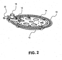
- the circular member shown in Figure 1 is brake ring 10.
- a plurality of holes and/or grooves can be formed in the circular member.
- the holes and grooves may be formed by any suitable technique such as, for example, drilling, milling, or molding.
- brake ring 10 is coupled to swivel ring 12, which is coupled to base assembly 24 (shown in Figure 3).
- Inner swivel 14 has bearings 16 (Figure 1) that can move within track 17 of swivel ring 12.
- each bearing 16 only contacts track 17 at two points.
- each bearing 16 may contact the upper edge of track 17 and the lower edge of track 17.
- Such a configuration advantageously reduces friction between bearings 16 and track 17 to improve movement of inner swivel 14 relative to swivel ring 12.
- Brake housing 18 is coupled to inner swivel 14 by brake bracket 19. This allows brake housing 18 to rotate with inner swivel 14 relative to brake ring 10 and swivel ring 12. In alternative embodiments, brake housing 18 remains stationary while brake ring 10 is capable of rotation.
- brake housing 18 comprises a caliper with opening 20 to receive brake ring 10.
- the caliper may include a first resilient member (e.g., an internal spring) to bias braking element 40 ( Figure 4) against at least one of a top side and a bottom side of brake ring 10. In this manner, the caliper is capable of applying a braking force to brake ring 10 via braking element 40.
- a first resilient member e.g., an internal spring
- Figure 3 shows an embodiment in which seat assembly 28 is coupled to inner swivel 14 (e.g., via linear bearing 26) so that seat 30 may be rotated relative to base assembly 24.
- brake ring 10 remains stationary while inner swivel 14 and seat assembly 28 are capable of rotation.
- cable 34 is provided to enable a user to reduce the braking force applied to the circular member (e.g., brake ring 10) such that seat assembly 28 may be rotated.
- the proximal end of cable 34 may be attached to cable interface 22 of brake housing 18 ( Figures 3 and 4 ).
- the distal end of cable 34 may be attached to brake handle 32 to permit a user to change the tension on cable 34 in order to effect a change in the amount of braking force applied to brake ring 10.
- Brake handle 32 is coupled to arm rest 31 of seat 30.
- the tension adjustment mechanism e.g., brake handle 32 or suitable alternative
- the tension adjustment mechanism may be disposed in any suitable location.
- Figure 4 shows an embodiment in which cable 34 is coupled (e.g., via cable interface 22) to the caliper to control the amount of braking force applied to brake ring 10.
- the caliper comprises a resilient member (e.g., a spring disposed within brake housing 18) and braking element 40.
- the connection between cable 34 and the caliper is such that a change in the tension of cable 34 can release the caliper from a biased position, in which braking element 40 is biased against the circular member disposed within opening 20 of the caliper.
- the tension of cable 34 is increased to overcome the bias of the resilient member, the amount of force exerted on the circular member by braking element 40 is reduced to permit movement of seat assembly 28.
- an adjustable resilient member e.g., spring 38
- spring 38 can be used to adjust the amount of braking force exerted by the caliper in the biased position on the circular member.
- spring 38 is disposed around cable interface 22 and has one end butted against (or coupled to) brake housing 18 and the other end coupled to stop 36.
- Such a configuration is only one example of a mechanism for adjusting the braking force applied by the caliper in the biased position.
- braking force can also be used to control movement in other directions (e.g., fore and aft movement, as well as transverse).
- the braking mechanisms used to control movement in the other directions may work on the same or different principles as those disclosed herein.
- Figure 5 shows one embodiment of a cable system that can actuate a plurality of braking mechanisms associated with the movement of a seat assembly.
- tension splitter 42 may be coupled to cable 34 such that the tension applied by the user with handle 32 ( Figure 3 ) is divided among two or more cables (e.g. 44A, 44B, and 44C) to control different braking mechanisms.
- cable 44A could be coupled to the braking mechanism to control fore and aft movement
- cable 44B could be coupled to the braking mechanism to control transverse movement
- cable 44C could be coupled to the braking mechanism to control rotational movement.
- FIG. 3 shows one example of how base assembly 24 may be coupled to a portion of a vehicle (e.g., floor 23).
- various embodiments may include a band that is disposed around the circumference of the disc (or ring) such that the band is biased to apply a frictional force to the disc to prevent rotational movement.
- the disc may also have a circumferential recess in which the band is disposed. The recess helps the band remain engaged with the disc.
- the user can actuate a cable to reduce to amount of braking force (e.g., friction) exerted on the disc. Similar to the other embodiments, the user may allow the cable to return to the biased position, in which the band tightens around the disc to prevent rotational movement.
- a drum assembly may be used in place of a brake disc, and a brake shoe assembly may be used in place of a caliper.
- at least one brake shoe is biased against the inner and/or the outer surface of the drum assembly.
- various embodiments may include a cable to permit a user to reduce the braking force applied to the drum assembly, allowing the seat to rotate. Once the user has chosen a desired rotational orientation, the cable may be released so that the braking mechanism returns to the biased state in which the brake shoe assembly applies enough braking force to prevent rotational movement of the seat.
Landscapes
- Engineering & Computer Science (AREA)
- Aviation & Aerospace Engineering (AREA)
- Transportation (AREA)
- Mechanical Engineering (AREA)
- Braking Arrangements (AREA)
Applications Claiming Priority (2)
| Application Number | Priority Date | Filing Date | Title |
|---|---|---|---|
| US409976 | 1995-03-24 | ||
| US10/409,976 US6938957B2 (en) | 2003-04-07 | 2003-04-07 | Rotation lock mechanism for aircraft seat |
Related Child Applications (2)
| Application Number | Title | Priority Date | Filing Date |
|---|---|---|---|
| EP11004281.9 Division-Into | 2011-05-24 | ||
| EP11004425.2 Division-Into | 2011-05-24 |
Publications (3)
| Publication Number | Publication Date |
|---|---|
| EP1466780A2 true EP1466780A2 (de) | 2004-10-13 |
| EP1466780A3 EP1466780A3 (de) | 2008-07-09 |
| EP1466780B1 EP1466780B1 (de) | 2013-05-22 |
Family
ID=32869204
Family Applications (1)
| Application Number | Title | Priority Date | Filing Date |
|---|---|---|---|
| EP04008245.5A Expired - Lifetime EP1466780B1 (de) | 2003-04-07 | 2004-04-05 | Blockiermechanismus für Flugzeugdrehsitz |
Country Status (2)
| Country | Link |
|---|---|
| US (1) | US6938957B2 (de) |
| EP (1) | EP1466780B1 (de) |
Cited By (2)
| Publication number | Priority date | Publication date | Assignee | Title |
|---|---|---|---|---|
| DE102006013143A1 (de) * | 2006-03-20 | 2007-09-27 | Airbus Deutschland Gmbh | Gastronomieabteil für ein Transportmittel für Passagiere |
| CN106427682A (zh) * | 2016-11-24 | 2017-02-22 | 江苏忠明祥和精工股份有限公司 | 汽车座椅用转盘 |
Families Citing this family (24)
| Publication number | Priority date | Publication date | Assignee | Title |
|---|---|---|---|---|
| US7600732B2 (en) * | 2006-08-14 | 2009-10-13 | Ami Industries, Inc. | Aircraft interior equipment support |
| US8152101B2 (en) * | 2006-09-12 | 2012-04-10 | Law Sondra F | System and method for integrating handicapped accessible seats into aircraft interior configurations |
| US7891629B2 (en) * | 2006-11-02 | 2011-02-22 | Labrador Development Llc | Rotatable chair support |
| US7866751B2 (en) * | 2007-10-02 | 2011-01-11 | Brunswick Corporation | Apparatus and methods to integrally form lever operated cables with vehicle seats |
| US7533930B1 (en) * | 2007-10-24 | 2009-05-19 | Embraer - Empresa Brasileira De Aeronautica S.A. | Convertible aircraft passenger seat and method |
| EP2344408B1 (de) * | 2008-09-22 | 2014-05-14 | Crown Equipment Corporation | Schwenkbarer sitz mit einstellbarem schwenkwiderstand |
| US9051053B2 (en) | 2013-01-10 | 2015-06-09 | Textron Innovations, Inc. | Seat base for aircraft |
| US9428276B1 (en) | 2015-02-19 | 2016-08-30 | PAC Seating Systems, Inc. | Swivel mechanism for vehicle seat |
| US10155591B2 (en) | 2016-04-15 | 2018-12-18 | Goodrich Corporation | Rotational brake assembly for a seat locking mechanism |
| US10155590B2 (en) * | 2016-04-15 | 2018-12-18 | Goodrich Corporation | Override bypass assembly for a seat locking mechanism |
| US9849813B2 (en) | 2016-04-15 | 2017-12-26 | Goodrich Corporation | Carriage assembly for a seat locking mechanism |
| US9908446B2 (en) * | 2016-04-15 | 2018-03-06 | Goodrich Corporation | Electric motor assembly for a seat locking mechanism |
| US20190038490A1 (en) * | 2017-06-12 | 2019-02-07 | Torrance D. Lillevold | Rotational Transfer Platform System |
| CN107364797B (zh) * | 2017-08-28 | 2018-09-11 | 沈阳安洋自控设备有限公司 | 一种联动台旋转底座 |
| CN207725260U (zh) * | 2017-11-28 | 2018-08-14 | 延锋安道拓座椅有限公司 | 一种锁止装置 |
| US11110023B1 (en) * | 2019-04-02 | 2021-09-07 | Boyd Industries, Inc. | Chair with swivel and brake system |
| US10994644B2 (en) * | 2019-04-10 | 2021-05-04 | B/E Aerospace, Inc. | Lock mechanism for rotary component control |
| US10894495B2 (en) | 2019-05-29 | 2021-01-19 | Gulfstream Aerospace Corporation | Seat assembly including an armrest with a lever handle and method for making the same |
| JP2022014373A (ja) * | 2020-07-06 | 2022-01-19 | トヨタ自動車株式会社 | 車両用シート及び車両 |
| CN218327243U (zh) * | 2022-04-15 | 2023-01-17 | 深圳市玛威尔显控科技有限公司 | 一种高稳定性的360度环拍平台 |
| US20240253530A1 (en) * | 2023-01-12 | 2024-08-01 | Textron Aviation Inc. | Swivel Locking System |
| US12427901B2 (en) * | 2023-03-13 | 2025-09-30 | Caterpillar Paving Products Inc. | Plate and enclosure assembly for use in construction equipment |
| US12534208B2 (en) * | 2023-08-02 | 2026-01-27 | Textron Innovations Inc. | Swivel indicating mechanism for aircraft seat |
| US12595064B2 (en) * | 2023-10-03 | 2026-04-07 | Textron Innovations Inc. | Swivel locking mechanism for aircraft seat |
Family Cites Families (26)
| Publication number | Priority date | Publication date | Assignee | Title |
|---|---|---|---|---|
| US3622202A (en) * | 1969-07-07 | 1971-11-23 | Vernon C Brown | Adjustable chair and control therefor |
| FI49708C (fi) * | 1972-11-17 | 1975-09-10 | Oulu Oy | Menetelmä arvotuotteiden valmistamiseksi mäntypiestä. |
| US3858834A (en) * | 1974-01-02 | 1975-01-07 | Universal Oil Prod Co | Locking mechanism for pedestal seat |
| US3926396A (en) | 1974-06-12 | 1975-12-16 | Universal Oil Prod Co | Locking mechanism for pedestal seat |
| US4097016A (en) * | 1977-05-12 | 1978-06-27 | Danbar, Inc. | Rotatable seat support assembly |
| US4671572A (en) * | 1983-12-23 | 1987-06-09 | Erda, Inc. | Adjustable chair having roller cam adjustment mechanism |
| US4588226A (en) * | 1983-12-23 | 1986-05-13 | Erda, Inc. | Adjustable chair for aircraft and the like |
| US4756502A (en) * | 1986-06-26 | 1988-07-12 | Nordam | Aircraft seat |
| US4705256A (en) * | 1986-07-23 | 1987-11-10 | Seats, Inc. | Swivel seat pedestal |
| US4893871A (en) * | 1988-12-12 | 1990-01-16 | Hickory Springs Manufacturing Co. | Swivel rocker stop assembly |
| FR2684609B1 (fr) * | 1991-12-10 | 1994-02-11 | Faure Automobile Bertrand | Base tournante a securite permettant la rotation de 180degre d'un siege dans un vehicule automobile ou analogue. |
| GB2301620B (en) * | 1992-11-26 | 1997-07-02 | Kab Seating Ltd | Seats |
| DE4409841C2 (de) * | 1993-06-04 | 2001-03-22 | Honda Motor Co Ltd | Raupen-Laufband für Raupenkraftfahrzeuge |
| CA2119341A1 (en) * | 1993-08-13 | 1995-02-14 | Vittorio Infanti | Adjustable game stool assembly |
| US5634537A (en) | 1995-04-19 | 1997-06-03 | Lord Corporation | Locking and positioning device |
| US5568960A (en) * | 1995-09-15 | 1996-10-29 | Aircraft Modular Products, Inc. | Aircraft passenger seat swivel assembly |
| US5733006A (en) * | 1996-05-02 | 1998-03-31 | Sears Manufacturing Company | Swivel seat suspension with free-swivel feature |
| EP0812722B1 (de) * | 1996-06-14 | 2003-05-02 | Ikeda Bussan Co., Ltd. | Drehbare Vorrichtung für Kraftfahrzeugsitze |
| US5951106A (en) * | 1996-09-13 | 1999-09-14 | Ikeda Bussan Co., Ltd. | Rotatable vehicle seat assembly with improved latching mechanism |
| JP3431773B2 (ja) * | 1996-09-27 | 2003-07-28 | アイシン精機株式会社 | 車両用回転式シート装置 |
| US5904399A (en) * | 1997-09-25 | 1999-05-18 | Hanil Company Ltd. | Rotary table of a seat for automobiles |
| US6116183A (en) * | 1998-10-01 | 2000-09-12 | Attwood Corporation | Positively locking boat seat and method for making the same |
| US6361111B1 (en) * | 1998-11-18 | 2002-03-26 | Electric Mobility Corporation | Rotational adjustment device |
| US6536842B2 (en) * | 1998-11-18 | 2003-03-25 | Electric Molorlity Corporation | Rotational adjustment device |
| DE20006169U1 (de) * | 2000-04-04 | 2001-08-09 | Johnson Controls GmbH, 51399 Burscheid | Vorrichtung zur Einstellung der Längsposition eines Fahrzeugsitzes |
| US6578854B2 (en) * | 2001-07-30 | 2003-06-17 | Solorider Industries, Inc. | Personal mobility vehicle incorporating tilting and swiveling seat and method for use while playing golf |
-
2003
- 2003-04-07 US US10/409,976 patent/US6938957B2/en not_active Expired - Lifetime
-
2004
- 2004-04-05 EP EP04008245.5A patent/EP1466780B1/de not_active Expired - Lifetime
Cited By (2)
| Publication number | Priority date | Publication date | Assignee | Title |
|---|---|---|---|---|
| DE102006013143A1 (de) * | 2006-03-20 | 2007-09-27 | Airbus Deutschland Gmbh | Gastronomieabteil für ein Transportmittel für Passagiere |
| CN106427682A (zh) * | 2016-11-24 | 2017-02-22 | 江苏忠明祥和精工股份有限公司 | 汽车座椅用转盘 |
Also Published As
| Publication number | Publication date |
|---|---|
| US6938957B2 (en) | 2005-09-06 |
| US20040195886A1 (en) | 2004-10-07 |
| EP1466780B1 (de) | 2013-05-22 |
| EP1466780A3 (de) | 2008-07-09 |
Similar Documents
| Publication | Publication Date | Title |
|---|---|---|
| US6938957B2 (en) | Rotation lock mechanism for aircraft seat | |
| US4466664A (en) | Seat with a reclining back and an armrest | |
| CA2246420C (en) | Actuator that adjusts to side loads automatically by pivoting internally | |
| CN111806697B (zh) | 用于转动部件控制的锁定机构 | |
| US7296857B2 (en) | Vehicle seat reclining device | |
| US11766957B2 (en) | Release mechanism for seat recliner assembly | |
| US20130270884A1 (en) | Recliner mechanism with dump feature | |
| US20080030061A1 (en) | Multi-position adjustment mechanism | |
| US9994128B2 (en) | Seat sliding device for vehicle | |
| WO2002016162A1 (en) | Compact disc recliner | |
| US6267443B1 (en) | Reclining seat for vehicle | |
| CA2195088A1 (en) | Infinitely adjustable linear actuator | |
| EP1556243B1 (de) | Vorrichtung zum verriegeln der konfiguration einer einrichtung,wie zum beispiel eines fahrzeugsitzes | |
| CA2669168A1 (en) | Customizable pedal system | |
| US5556165A (en) | Infinitely adjustable linear actuator for vehicle seat | |
| US20050015929A1 (en) | Braking system for braking a first element relative to a second element, and a vehicle seat including such a braking system | |
| CN111806698B (zh) | 转动靠背倾斜机构 | |
| US5607032A (en) | Rotatable shaft lock apparatus | |
| EP0425237A2 (de) | Neigungsverstellvorrichtung für einen Kraftfahrzeugsitz | |
| CA2812408C (en) | Recliner mechanism with dump feature | |
| CN220655180U (zh) | 椅背前倾机构及座椅 | |
| EP3398805B1 (de) | Gesicherte vorrichtung zum drehen eines sitzes, insbesondere für ein schienenfahrzeug | |
| EP4436874A1 (de) | Sicherheitsgurt-befestigungssystem für einen beweglichen sitz | |
| JPH06296528A (ja) | スプリングの予圧調整装置 |
Legal Events
| Date | Code | Title | Description |
|---|---|---|---|
| PUAI | Public reference made under article 153(3) epc to a published international application that has entered the european phase |
Free format text: ORIGINAL CODE: 0009012 |
|
| AK | Designated contracting states |
Kind code of ref document: A2 Designated state(s): AT BE BG CH CY CZ DE DK EE ES FI FR GB GR HU IE IT LI LU MC NL PL PT RO SE SI SK TR |
|
| AX | Request for extension of the european patent |
Extension state: AL HR LT LV MK |
|
| RIN1 | Information on inventor provided before grant (corrected) |
Inventor name: HUTCHISON, CARL R. Inventor name: TRAUBE, JOHN H. Inventor name: HEMMER, NATHAN A. Inventor name: BEATTY, GEORGE T. |
|
| PUAL | Search report despatched |
Free format text: ORIGINAL CODE: 0009013 |
|
| AK | Designated contracting states |
Kind code of ref document: A3 Designated state(s): AT BE BG CH CY CZ DE DK EE ES FI FR GB GR HU IE IT LI LU MC NL PL PT RO SE SI SK TR |
|
| AX | Request for extension of the european patent |
Extension state: AL HR LT LV MK |
|
| 17P | Request for examination filed |
Effective date: 20090108 |
|
| AKX | Designation fees paid |
Designated state(s): AT BE BG CH CY CZ DE DK EE ES FI FR GB GR HU IE IT LI LU MC NL PL PT RO SE SI SK TR |
|
| 17Q | First examination report despatched |
Effective date: 20090514 |
|
| RAP1 | Party data changed (applicant data changed or rights of an application transferred) |
Owner name: GOODRICH CORPORATION |
|
| GRAP | Despatch of communication of intention to grant a patent |
Free format text: ORIGINAL CODE: EPIDOSNIGR1 |
|
| GRAS | Grant fee paid |
Free format text: ORIGINAL CODE: EPIDOSNIGR3 |
|
| GRAP | Despatch of communication of intention to grant a patent |
Free format text: ORIGINAL CODE: EPIDOSNIGR1 |
|
| GRAA | (expected) grant |
Free format text: ORIGINAL CODE: 0009210 |
|
| AK | Designated contracting states |
Kind code of ref document: B1 Designated state(s): AT BE BG CH CY CZ DE DK EE ES FI FR GB GR HU IE IT LI LU MC NL PL PT RO SE SI SK TR |
|
| REG | Reference to a national code |
Ref country code: GB Ref legal event code: FG4D |
|
| REG | Reference to a national code |
Ref country code: CH Ref legal event code: EP |
|
| REG | Reference to a national code |
Ref country code: AT Ref legal event code: REF Ref document number: 613031 Country of ref document: AT Kind code of ref document: T Effective date: 20130615 |
|
| REG | Reference to a national code |
Ref country code: IE Ref legal event code: FG4D |
|
| REG | Reference to a national code |
Ref country code: DE Ref legal event code: R096 Ref document number: 602004042156 Country of ref document: DE Effective date: 20130711 |
|
| REG | Reference to a national code |
Ref country code: AT Ref legal event code: MK05 Ref document number: 613031 Country of ref document: AT Kind code of ref document: T Effective date: 20130522 |
|
| PG25 | Lapsed in a contracting state [announced via postgrant information from national office to epo] |
Ref country code: GR Free format text: LAPSE BECAUSE OF FAILURE TO SUBMIT A TRANSLATION OF THE DESCRIPTION OR TO PAY THE FEE WITHIN THE PRESCRIBED TIME-LIMIT Effective date: 20130823 Ref country code: FI Free format text: LAPSE BECAUSE OF FAILURE TO SUBMIT A TRANSLATION OF THE DESCRIPTION OR TO PAY THE FEE WITHIN THE PRESCRIBED TIME-LIMIT Effective date: 20130522 Ref country code: PT Free format text: LAPSE BECAUSE OF FAILURE TO SUBMIT A TRANSLATION OF THE DESCRIPTION OR TO PAY THE FEE WITHIN THE PRESCRIBED TIME-LIMIT Effective date: 20130923 Ref country code: SI Free format text: LAPSE BECAUSE OF FAILURE TO SUBMIT A TRANSLATION OF THE DESCRIPTION OR TO PAY THE FEE WITHIN THE PRESCRIBED TIME-LIMIT Effective date: 20130522 Ref country code: ES Free format text: LAPSE BECAUSE OF FAILURE TO SUBMIT A TRANSLATION OF THE DESCRIPTION OR TO PAY THE FEE WITHIN THE PRESCRIBED TIME-LIMIT Effective date: 20130902 Ref country code: SE Free format text: LAPSE BECAUSE OF FAILURE TO SUBMIT A TRANSLATION OF THE DESCRIPTION OR TO PAY THE FEE WITHIN THE PRESCRIBED TIME-LIMIT Effective date: 20130522 Ref country code: AT Free format text: LAPSE BECAUSE OF FAILURE TO SUBMIT A TRANSLATION OF THE DESCRIPTION OR TO PAY THE FEE WITHIN THE PRESCRIBED TIME-LIMIT Effective date: 20130522 |
|
| REG | Reference to a national code |
Ref country code: NL Ref legal event code: VDEP Effective date: 20130522 |
|
| PG25 | Lapsed in a contracting state [announced via postgrant information from national office to epo] |
Ref country code: BG Free format text: LAPSE BECAUSE OF FAILURE TO SUBMIT A TRANSLATION OF THE DESCRIPTION OR TO PAY THE FEE WITHIN THE PRESCRIBED TIME-LIMIT Effective date: 20130822 Ref country code: PL Free format text: LAPSE BECAUSE OF FAILURE TO SUBMIT A TRANSLATION OF THE DESCRIPTION OR TO PAY THE FEE WITHIN THE PRESCRIBED TIME-LIMIT Effective date: 20130522 |
|
| PG25 | Lapsed in a contracting state [announced via postgrant information from national office to epo] |
Ref country code: CZ Free format text: LAPSE BECAUSE OF FAILURE TO SUBMIT A TRANSLATION OF THE DESCRIPTION OR TO PAY THE FEE WITHIN THE PRESCRIBED TIME-LIMIT Effective date: 20130522 Ref country code: BE Free format text: LAPSE BECAUSE OF FAILURE TO SUBMIT A TRANSLATION OF THE DESCRIPTION OR TO PAY THE FEE WITHIN THE PRESCRIBED TIME-LIMIT Effective date: 20130522 Ref country code: EE Free format text: LAPSE BECAUSE OF FAILURE TO SUBMIT A TRANSLATION OF THE DESCRIPTION OR TO PAY THE FEE WITHIN THE PRESCRIBED TIME-LIMIT Effective date: 20130522 Ref country code: DK Free format text: LAPSE BECAUSE OF FAILURE TO SUBMIT A TRANSLATION OF THE DESCRIPTION OR TO PAY THE FEE WITHIN THE PRESCRIBED TIME-LIMIT Effective date: 20130522 Ref country code: SK Free format text: LAPSE BECAUSE OF FAILURE TO SUBMIT A TRANSLATION OF THE DESCRIPTION OR TO PAY THE FEE WITHIN THE PRESCRIBED TIME-LIMIT Effective date: 20130522 |
|
| PG25 | Lapsed in a contracting state [announced via postgrant information from national office to epo] |
Ref country code: RO Free format text: LAPSE BECAUSE OF FAILURE TO SUBMIT A TRANSLATION OF THE DESCRIPTION OR TO PAY THE FEE WITHIN THE PRESCRIBED TIME-LIMIT Effective date: 20130522 Ref country code: IT Free format text: LAPSE BECAUSE OF FAILURE TO SUBMIT A TRANSLATION OF THE DESCRIPTION OR TO PAY THE FEE WITHIN THE PRESCRIBED TIME-LIMIT Effective date: 20130522 Ref country code: NL Free format text: LAPSE BECAUSE OF FAILURE TO SUBMIT A TRANSLATION OF THE DESCRIPTION OR TO PAY THE FEE WITHIN THE PRESCRIBED TIME-LIMIT Effective date: 20130522 |
|
| PLBE | No opposition filed within time limit |
Free format text: ORIGINAL CODE: 0009261 |
|
| STAA | Information on the status of an ep patent application or granted ep patent |
Free format text: STATUS: NO OPPOSITION FILED WITHIN TIME LIMIT |
|
| 26N | No opposition filed |
Effective date: 20140225 |
|
| REG | Reference to a national code |
Ref country code: DE Ref legal event code: R097 Ref document number: 602004042156 Country of ref document: DE Effective date: 20140225 |
|
| REG | Reference to a national code |
Ref country code: DE Ref legal event code: R119 Ref document number: 602004042156 Country of ref document: DE |
|
| PG25 | Lapsed in a contracting state [announced via postgrant information from national office to epo] |
Ref country code: MC Free format text: LAPSE BECAUSE OF FAILURE TO SUBMIT A TRANSLATION OF THE DESCRIPTION OR TO PAY THE FEE WITHIN THE PRESCRIBED TIME-LIMIT Effective date: 20130522 Ref country code: LU Free format text: LAPSE BECAUSE OF FAILURE TO SUBMIT A TRANSLATION OF THE DESCRIPTION OR TO PAY THE FEE WITHIN THE PRESCRIBED TIME-LIMIT Effective date: 20140405 |
|
| REG | Reference to a national code |
Ref country code: CH Ref legal event code: PL |
|
| GBPC | Gb: european patent ceased through non-payment of renewal fee |
Effective date: 20140405 |
|
| REG | Reference to a national code |
Ref country code: DE Ref legal event code: R119 Ref document number: 602004042156 Country of ref document: DE Effective date: 20141101 |
|
| REG | Reference to a national code |
Ref country code: FR Ref legal event code: ST Effective date: 20141231 |
|
| REG | Reference to a national code |
Ref country code: IE Ref legal event code: MM4A |
|
| PG25 | Lapsed in a contracting state [announced via postgrant information from national office to epo] |
Ref country code: DE Free format text: LAPSE BECAUSE OF NON-PAYMENT OF DUE FEES Effective date: 20141101 Ref country code: CH Free format text: LAPSE BECAUSE OF NON-PAYMENT OF DUE FEES Effective date: 20140430 Ref country code: LI Free format text: LAPSE BECAUSE OF NON-PAYMENT OF DUE FEES Effective date: 20140430 Ref country code: GB Free format text: LAPSE BECAUSE OF NON-PAYMENT OF DUE FEES Effective date: 20140405 |
|
| PG25 | Lapsed in a contracting state [announced via postgrant information from national office to epo] |
Ref country code: FR Free format text: LAPSE BECAUSE OF NON-PAYMENT OF DUE FEES Effective date: 20140430 |
|
| PG25 | Lapsed in a contracting state [announced via postgrant information from national office to epo] |
Ref country code: IE Free format text: LAPSE BECAUSE OF NON-PAYMENT OF DUE FEES Effective date: 20140405 |
|
| PG25 | Lapsed in a contracting state [announced via postgrant information from national office to epo] |
Ref country code: CY Free format text: LAPSE BECAUSE OF FAILURE TO SUBMIT A TRANSLATION OF THE DESCRIPTION OR TO PAY THE FEE WITHIN THE PRESCRIBED TIME-LIMIT Effective date: 20130522 |
|
| PG25 | Lapsed in a contracting state [announced via postgrant information from national office to epo] |
Ref country code: HU Free format text: LAPSE BECAUSE OF FAILURE TO SUBMIT A TRANSLATION OF THE DESCRIPTION OR TO PAY THE FEE WITHIN THE PRESCRIBED TIME-LIMIT; INVALID AB INITIO Effective date: 20040405 Ref country code: TR Free format text: LAPSE BECAUSE OF FAILURE TO SUBMIT A TRANSLATION OF THE DESCRIPTION OR TO PAY THE FEE WITHIN THE PRESCRIBED TIME-LIMIT Effective date: 20130522 |