EP1466847B1 - Verfahren und Vorrichtung zum Umlegen von Glastafeln - Google Patents
Verfahren und Vorrichtung zum Umlegen von Glastafeln Download PDFInfo
- Publication number
- EP1466847B1 EP1466847B1 EP03008388A EP03008388A EP1466847B1 EP 1466847 B1 EP1466847 B1 EP 1466847B1 EP 03008388 A EP03008388 A EP 03008388A EP 03008388 A EP03008388 A EP 03008388A EP 1466847 B1 EP1466847 B1 EP 1466847B1
- Authority
- EP
- European Patent Office
- Prior art keywords
- glass pane
- glass
- conveyor
- edge
- support
- Prior art date
- Legal status (The legal status is an assumption and is not a legal conclusion. Google has not performed a legal analysis and makes no representation as to the accuracy of the status listed.)
- Expired - Lifetime
Links
Images

Classifications
-
- B—PERFORMING OPERATIONS; TRANSPORTING
- B65—CONVEYING; PACKING; STORING; HANDLING THIN OR FILAMENTARY MATERIAL
- B65G—TRANSPORT OR STORAGE DEVICES, e.g. CONVEYORS FOR LOADING OR TIPPING, SHOP CONVEYOR SYSTEMS OR PNEUMATIC TUBE CONVEYORS
- B65G49/00—Conveying systems characterised by their application for specified purposes not otherwise provided for
- B65G49/05—Conveying systems characterised by their application for specified purposes not otherwise provided for for fragile or damageable materials or articles
- B65G49/06—Conveying systems characterised by their application for specified purposes not otherwise provided for for fragile or damageable materials or articles for fragile sheets, e.g. glass
- B65G49/067—Sheet handling, means, e.g. manipulators, devices for turning or tilting sheet glass
Definitions
- the invention relates to a method and a device for folding of tabular objects.
- the folding of glass from one opposite the vertical by a few degrees (for example 5 °) "backwards" inclined, ie essentially vertical position in a substantially horizontal position.
- the invention is based on the object, a method and a Specify device of the type mentioned, the simple and can be executed without considerable design effort and Nevertheless, a gentle and quick flipping of glass panes possible power.
- the glass is "after dropped down behind, meaning she falls over to the side, to which it is already inclined to the perpendicular (something). It is advantageous in the invention when the glass so is aligned, in the opposite to the perpendicular slightly inclined position (starting position) the "nicer" side, which optionally carries a coating facing upward, so that this side of the folded glass then also upwards has. This is easily achieved by simply placing the glass is allowed to fall over “backwards”. So it is in the invention Generally not required glass sheets from a position in the they are inclined to the vertical to one side, to erect and then fall over to the other side.
- the procedure according to the invention can be such that the Glass panel standing on the bottom of a conveyor and on top a support device, optionally with a roller line equipped, is moved adjacent to the starting position, off which she is then allowed to fall over.
- the conveyor on which the glass panel gets up with its lower edge, essentially vertically adjustable to the track of the glass pane (lower edge) be.
- the glass pane in the starting position relative to the support surface, towards the glass pane is turned down, aligned so that the glass sheets, after they have fallen over, independent on the support surface come to rest from their size in a predeterminable position and are aligned. So the circumstance can be taken into account that larger glass panes, after they have fallen down, in the direction of fall Slightly slide on the support surface, this one Piece is larger than the piece to slip the smaller glass panes.
- the support of the upper edge of the glass can also be in be adjustable horizontally.
- the starting position of the glass to adjust their size, with the aim of getting the previously lower edge the glass sheet after falling over the glass sheet on the support surface is in a predeterminable position is in particular of Advantage if the glass pane from the support surface with the help of Conveyors is moved away, since the glass in a defined reference position lies on the support surface. This is special advantageous if the glass pane from the support surface in substantially parallel to the previous one (i.e., in the initial position) Edge of the glass to be conveyed.
- the support surface can be tilted, wherein the tilting on the one hand determines the extent of the fall of the glass (ie the Angle around which the glass pane pivots when dropped).
- the bearing surface can be aligned so that a hassle Transport of the glass in a downstream device possible is, even if it is higher than the support surface.
- the Transport device on which the lower edge of the glass stands up, either a row of rollers or a conveyor belt, the Transport device preferably on a guide transversely to the conveying direction is adjustable.
- the device for supporting the upper edge of the glass pane in the starting position is in one embodiment a series of (free rotatable) rollers or an endless belt, which on a beam, the is mounted vertically adjustable, are arranged.
- the Castors or the belt preferably from the beam vertically down.
- the Shape of the rollers is arbitrary, with cone rollers or cylindrical Roles are also considered.
- the supporting device for the upper edge of the glass pane in her Starting position can also be adjusted horizontally. In one embodiment is this adjustment with the adjustment of the lower Synchronized conveyor, so that the glass pane in the Starting position always assumes the same angle to the vertical.
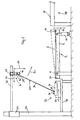
- Fig. 1 in an oblique view of a device according to the invention for free Dropping glass to make these from a substantially vertical position in a substantially horizontal position and
- FIG. 2 the device of Fig. 1 seen from the left of Fig. 1 from.
- the apparatus shown in Figs. 1 and 2 for transferring glass panes 26 in a substantially horizontal position has as Supporting a table 2 with a table top 4, at the top a damping pad 6 is provided.
- the steaming pad 6 may be, for example, a felt pad.
- the table 2 can as Air cushion table be designed to carry off on him To relocate folded glass panes away from table 2.
- conveyors such as retractable and liftable conveyor belts or conveyor rollers or rollers, be integrated.
- the table top 4 is at its left in Fig. 1 edge about an axis. 8 with the aid of pressure medium motors 10 in the direction of the double arrow 12th adjustable so that the table 2 consists of a substantially horizontal Position in a dashed line in Fig. 1 drawn obliquely Location can be swiveled.
- the in Fig. 1 right edge 14 of the table top 4 substantially in the same Height arranged as the working surface 16 of a shown in Fig. 1, downstream device 18.
- the edge 20 of the table 2 is a conveyor 22 provided.
- the conveyor 22 may serve as a conveyor 24 have an endless conveyor belt or rotationally driven rollers.
- As a means of promotion are also endless chains with (hook-shaped) Supports for glass 26 conceivable.
- a glass plate 26 is available its lower edge 28 on the conveyor 24 of the conveyor 22 on.
- By a guide 30 prevents the lower edge 28 of the glass sheet 26 transversely to the conveying direction of the conveyor 22 (arrow 32 in Fig. 2) emigrates when a glass plate 26 in the Device is transported.
- the upper edge 29 of the glass sheet 26 is supported by a support 40 held.
- the support device 40 has a bar 42, on the downward facing rollers 44 are arranged.
- the rollers 44 can be freely rotatable or, if desired, with a rotary drive for Support the transport of glass panes 26 equipped.
- the beam 42 is in the embodiment shown at a substantially horizontal guide 46 slidable via carriage 48 guided.
- the conveyor 22 is on guides 34 in the direction of Double arrow 36 (Fig. 1) adjustable.
- the support means 40 in the direction of the double arrow 50 may be a Glass pane 26 in its starting position shown in Fig. 1 (ie before it is allowed to fall) against the table 2 are aligned. It depends in particular on the orientation of the lower horizontal edge 28 of the glass sheet 26 relative to the table 2 at.
- the Adjustability of the support device 40 in the direction of the double arrow 50 in Fig. 1 is merely an optional and not necessarily mandatory measure.
- the support device 40 can also be selected, may be taken into account the fact that larger glass panes 26 after falling over on the table top 4 on, so a larger Sliding pieces as smaller glass panes 26.
- the starting position depending on the size of the glass sheet 26 can be achieved be that the glass sheets 26 - in particular the previously lower Edge 28 - on the table 2 always in one and the same position with a predetermined location arranged lower edge 28 of the glass 26 come to rest. This facilitates the removal of the Glass pane, in particular if the removal perpendicular to the image plane of Fig. 1 should take place.
- the guides 46 for the carriage 48 of the support 40 are over Carriage 52 on vertical guides 54 in the direction of the double arrow 56 adjustable up and down.
- This adjustability serves on the one hand to the support device to the size of a glass 26th adapt and on the other hand, the support means 40, in particular their rollers 44, from the region of the upper edge 29 of the glass sheet 26 to move in the direction of the double arrow 31st finally let them fall on the 6th edition Table top 4 of the table 2 comes to rest.
- the conveyor 22 and optionally the support means 40 adjustable in the direction of arrows 36 and 50, respectively are, ie substantially transversely to the surface extension of the glass sheet 26, the location of a pane of glass 26, after moving in the direction of the arrow 31 is dropped, defined on the table 2 because it can take account of the fact that smaller Glass panes 26 on the table 2 less "slip" than larger Glass panes 26.
- the device described can be used to carry out the invention
- the method can be used as follows:
- a glass plate 26, made of a glass warehouse, a carwash or the like. is brought up, with its lower edge 28 on the conveyor 22 upstanding and with its upper edge 29 at the support 40, in particular their rollers 44 fitting, in the direction of the arrow 32 transported into the device.
- the Glass pane 26, in particular its lower edge 28 by corresponding Adjusting the lower transport device 22 in the direction of Double arrow 36 (possibly also the upper support means 40 in Direction of the double arrow 50 adjusted) compared to the table 2 so has been aligned, that the glass sheet 26 after falling over is left on the table 2 assumes the desired position, the upper edge 29 of the glass sheet 26 by lifting the support 40 released and the glass 26 falls in the direction of the arrow 31 um.
- the glass pane 26 "falls over" to the rear, with a glass pane 26 is aligned so that their "nicer" Page 27, so the Side of the glass sheet 26, which may be a coating of metal or the like. carries, points upwards.
- a glass plate 26 on the support 6 of the table top 4 of the Table 2 After a glass plate 26 on the support 6 of the table top 4 of the Table 2 is, it can by non-illustrated conveyors, e.g. in the support table 2 embedded conveyor belts or transport rollers, in the direction of their track, they are in the starting position occupies (alignment of the lower edge 28 of the glass pane 26), ie essentially perpendicular to the image plane of FIG. 1, transported away become. But there is also the possibility of the glass pane in Direction away from the lower conveyor 22 away from the table 2 (ie transverse to the lower edge 28, i.e. to the right of FIG. 1) to move to a downstream device 18.
- non-illustrated conveyors e.g. in the support table 2 embedded conveyor belts or transport rollers, in the direction of their track, they are in the starting position occupies (alignment of the lower edge 28 of the glass pane 26), ie essentially perpendicular to the image plane of FIG. 1, transported away become
- the guide 54 for the carriage 52 be arranged in the area of the table 2.
- a glass panel 26 from a relative to the perpendicular slightly inclined Position in a substantially horizontal position fall over let the glass plate 26 with its lower edge 28 on a Conveyor 22 upstanding and with its upper edge 29 against a support device 40 moves adjacent to a starting position.
- a support device 40 moves adjacent to a starting position.
- By moving the support device 40 from the upper edge 29 of the Glass pane 26 is allowed to fall over to the rear, so they comes to rest on the support surface of a table 2.
- a glass sheet 26, with its "nicer" side 27 points up, another treatment, For example, a downstream device 18, fed become.
Landscapes
- Attitude Control For Articles On Conveyors (AREA)
- Re-Forming, After-Treatment, Cutting And Transporting Of Glass Products (AREA)
- Framework For Endless Conveyors (AREA)
- Joining Of Glass To Other Materials (AREA)
- Registering Or Overturning Sheets (AREA)
Description
Claims (23)
- Verfahren zum Umlegen von Glasscheiben (26) aus einer Ausgangslage, in der die Glasscheiben (16) gegenüber der Lotrechten geringfügig schräggestellt ist, in eine im wesentlichen horizontale Lage, wobei, die Glasscheibe (26) im Bereich ihres oberen Randes (29), durch eine Abstützung (40,44), die auf der nach unten weisenden Seite der Glasscheibe (26) anliegt, abgestützt wird, dadurch gekennzeichnet, dass die Glasscheibe (26) nach dem Wegbewegen der Abstützung (40,44) aus dem Bereich des oberen Randes (29) auf eine Auflagefläche (2) hin umfallen gelassen wird.
- Verfahren nach Anspruch 1, dadurch gekennzeichnet, dass die Glasscheibe (26), ohne sie zunächst in eine lotrechte Lage auszurichten, umfallen gelassen wird.
- Verfahren nach Anspruch 1 oder 2, dadurch gekennzeichnet, dass die Glasscheibe (26) mit ihrem unteren Rand (28) auf einer Fördereinrichtung (22) aufstehend in die Ausgangslage bewegt wird.
- Verfahren nach einem der Ansprüche 1 bis 3, dadurch gekennzeichnet, dass die Glasscheibe (26) mit ihrem oberen Rand (29) an einer Abstützeinrichtung (40) anliegend in die Ausgangslage bewegt wird.
- Verfahren nach einem der Ansprüche 1 bis 4, dadurch gekennzeichnet, dass wenigstens der Abstand des unteren Randes (28) der Glasscheibe (26) in einem vorbestimmten Abstand von der Auflagefläche (2), auf der die Glasscheibe (26) nach dem Umfallenlassen liegt, ausgerichtet wird.
- Verfahren nach Anspruch 5, dadurch gekennzeichnet, dass die Glasscheibe (26) mit ihrem unteren Rand durch Verstellen der Transporteinrichtung (22) quer zur Längserstreckung des unteren Randes (28) der Glasscheibe (26) ausgerichtet wird.
- Verfahren nach einem der Ansprüche 1 bis 6, dadurch gekennzeichnet, dass die Glasscheibe (26) durch Verstellen ihres oberen Randes (29) quer zur Längserstreckung des oberen Randes (29) ausgerichtet wird.
- Vorrichtung zum Umlegen von Glasscheiben (26) aus einer gegenüber der Lotrechten geringfügig geneigten Lage in eine im wesentlichen horizontale Lage, enthaltend einen Auflagetisch (2) für Glastafeln (26) in ihrer im wesentlichen horizontalen Lage, und eine Abstützeinrichtung (40,44) für den oberen Rand (29) der Glasscheibe (26), dadurch gekennzeichnet, dass die Abstützeinrichtung (40) für den oberen Rand (29) der Glasscheibe (26) zum Freigeben des oberen Randes (29) aus dem Bereich dieses Randes (29) wegbewegbar ist, und dass die Vorrichtung eine Fördereinrichtung (22) für den unteren horizontalen Rand (28) der Glasscheibe (26) enthält.
- Vorrichtung nach Anspruch 8, dadurch gekennzeichnet dass, die Abstützeinrichtung (40) nach oben abhebbar ist.
- Vorrichtung nach Anspruch 8 oder 9, dadurch gekennzeichnet dass, die Transporteinrichtung (22) quer zur Spur der in ihrer Ausgangslage stehenden Glasscheibe (26) (unterer Rand 28 derselben) verstellbar ist (Pfeil 36).
- Vorrichtung nach einem der Ansprüche 8 bis 10, dadurch gekennzeichnet dass, die Abstützeinrichtung (40) quer zur Längserstreckung des oberen Randes (29) der Glasscheibe (Pfeil 50) verstellbar ist.
- Vorrichtung nach einem der Ansprüche 8 bis 11, dadurch gekennzeichnet dass, die Abstützeinrichtung (40) für den oberen Rand (29) der Glasscheibe einen Balken (42) aufweist, der mit Rollen (44) bestückt ist.
- Vorrichtung nach Anspruch 12, dadurch gekennzeichnet dass, die Rollen (44) vom Balken (42) nach unten weisend angeordnet sind.
- Vorrichtung nach Anspruch 12 oder 13, dadurch gekennzeichnet dass, die Rollen (44) frei drehbare Rollen sind.
- Vorrichtung nach einem der Ansprüche 12 bis 14, dadurch gekennzeichnet dass, der Balken (42) über einen Schlitten (48) in horizontaler Richtung (Pfeil 50) verstellbar ist.
- Vorrichtung nach Anspruch 15, dadurch gekennzeichnet dass, die Schlitten (48) für den Balken (42) auf im wesentlichen horizontalen Führungen (46) verstellbar sind.
- Vorrichtung nach Anspruch 16, dadurch gekennzeichnet dass, die horizontale Führung (46) der Abstützung (40) über Schlitten (52) an lotrechten Führungen (54) verstellbar ist.
- Vorrichtung nach einem der Ansprüche 8 bis 17, dadurch gekennzeichnet dass, die Auflagefläche (2) wenigstens im Bereich ihres von der Fördereinrichtung (22) entfernten Randes (14) anhebbar ist.
- Vorrichtung nach einem der Ansprüche 8 bis 18, dadurch gekennzeichnet dass, die Fördereinrichtung (22) ein Förderband (24) aufweist.
- Vorrichtung nach einem der Ansprüche 8 bis 18, dadurch gekennzeichnet dass, die Fördereinrichtung (22) eine Rollenzeile drehangetriebener Rollen aufweist.
- Vorrichtung nach einem der Ansprüche 8 bis 20, dadurch gekennzeichnet dass, die Fördereinrichtung (22) auf Führungen (34) verschiebbar (Pfeil 36) ist.
- Vorrichtung nach einem der Ansprüche 8 bis 21, dadurch gekennzeichnet dass, die Fördereinrichtung (22) eine Führung (30) für den unteren Rand (28) der Glasscheibe (26) aufweist.
- Vorrichtung nach Anspruch 22, dadurch gekennzeichnet dass, die Führung (30) quer zur Fördereinrichtung (22) verstellbar ist.
Priority Applications (7)
| Application Number | Priority Date | Filing Date | Title |
|---|---|---|---|
| ES03008388T ES2232797T3 (es) | 2003-04-11 | 2003-04-11 | Procedimiento y dispositivo para cambiar de posicion lunas de cristal. |
| EP03008388A EP1466847B1 (de) | 2003-04-11 | 2003-04-11 | Verfahren und Vorrichtung zum Umlegen von Glastafeln |
| AT03008388T ATE282573T1 (de) | 2003-04-11 | 2003-04-11 | Verfahren und vorrichtung zum umlegen von glastafeln |
| DE50300159T DE50300159D1 (de) | 2003-04-11 | 2003-04-11 | Verfahren und Vorrichtung zum Umlegen von Glastafeln |
| CNA2004100328332A CN1550463A (zh) | 2003-04-11 | 2004-04-09 | 用于翻转板状物体特别是玻璃板的方法和装置 |
| RU2004110908/03A RU2265568C1 (ru) | 2003-04-11 | 2004-04-09 | Способ и устройство для переворачивания панелеобразных предметов, в частности стеклопанелей |
| US10/821,844 US20040213659A1 (en) | 2003-04-11 | 2004-04-12 | Process and device for transferring plate-shaped articles, especially panes of glass |
Applications Claiming Priority (1)
| Application Number | Priority Date | Filing Date | Title |
|---|---|---|---|
| EP03008388A EP1466847B1 (de) | 2003-04-11 | 2003-04-11 | Verfahren und Vorrichtung zum Umlegen von Glastafeln |
Publications (2)
| Publication Number | Publication Date |
|---|---|
| EP1466847A1 EP1466847A1 (de) | 2004-10-13 |
| EP1466847B1 true EP1466847B1 (de) | 2004-11-17 |
Family
ID=32864995
Family Applications (1)
| Application Number | Title | Priority Date | Filing Date |
|---|---|---|---|
| EP03008388A Expired - Lifetime EP1466847B1 (de) | 2003-04-11 | 2003-04-11 | Verfahren und Vorrichtung zum Umlegen von Glastafeln |
Country Status (7)
| Country | Link |
|---|---|
| US (1) | US20040213659A1 (de) |
| EP (1) | EP1466847B1 (de) |
| CN (1) | CN1550463A (de) |
| AT (1) | ATE282573T1 (de) |
| DE (1) | DE50300159D1 (de) |
| ES (1) | ES2232797T3 (de) |
| RU (1) | RU2265568C1 (de) |
Families Citing this family (4)
| Publication number | Priority date | Publication date | Assignee | Title |
|---|---|---|---|---|
| MD940149A (ro) * | 1993-06-17 | 1995-12-31 | Societatea Pe Actiuni "Microex" | Terminal |
| CA2553019A1 (en) * | 2004-01-16 | 2005-07-16 | Robert D. Smets | Streamlined pallet handling apparatus and method |
| US8108989B2 (en) | 2007-06-28 | 2012-02-07 | Crown Equipment Corporation | Manufacturing cell and elements of the cell |
| JP5078928B2 (ja) | 2009-02-27 | 2012-11-21 | 三菱重工業株式会社 | 反転装置 |
Family Cites Families (11)
| Publication number | Priority date | Publication date | Assignee | Title |
|---|---|---|---|---|
| US1699284A (en) * | 1926-10-05 | 1929-01-15 | Babcock Printing Press Mfg Com | Sheet rack for presses |
| US3399885A (en) * | 1966-02-03 | 1968-09-03 | Saint Gobain Corp | Glass sheet feeder for cutting and processing machines |
| SU422665A1 (ru) * | 1971-05-24 | 1974-04-05 | В. И. Ночевкин | Устройство для транспортирования плоских изделий в вертикальном направлении |
| JPS5259615A (en) * | 1975-11-12 | 1977-05-17 | Central Glass Co Ltd | Apparatus for carrying plates |
| FR2525196A1 (fr) * | 1982-04-16 | 1983-10-21 | Saint Gobain Vitrage | Dispositif pour le transfert de feuilles de verre d'un premier poste, ou elles sont en une position sensiblement verticale, jusqu'a un second poste, ou elles sont en une position sensiblement horizontale |
| SU1306917A1 (ru) * | 1985-07-22 | 1987-04-30 | Одесский филиал Всесоюзного научно-исследовательского и проектно-конструкторского института стекольного машиностроения | Устройство дл передачи листов стекла |
| EP0291083B1 (de) * | 1987-05-14 | 1991-03-27 | Erwin Jenkner | Verfahren und Anlage zum Überführen von Transportplattformen auf den Hubtisch einer Stapelstation |
| AT387765B (de) * | 1987-06-09 | 1989-03-10 | Lisec Peter | Einrichtung zum handhaben von abstandhalterrahmen |
| US5413204A (en) * | 1993-06-25 | 1995-05-09 | Central Glass Co., Ltd. | Glass plate positioning and supplying machine |
| DE59507786D1 (de) * | 1994-12-02 | 2000-03-16 | De La Rue Giori Sa | Stapelbrett zur Ablage eines Bogenstapels und Handhabungsautomat für derartige Stapelbretter |
| DE19600348C2 (de) * | 1996-01-08 | 2001-11-22 | Lewecke Maschb Gmbh | Regalanlage für Platten |
-
2003
- 2003-04-11 AT AT03008388T patent/ATE282573T1/de active
- 2003-04-11 DE DE50300159T patent/DE50300159D1/de not_active Expired - Lifetime
- 2003-04-11 EP EP03008388A patent/EP1466847B1/de not_active Expired - Lifetime
- 2003-04-11 ES ES03008388T patent/ES2232797T3/es not_active Expired - Lifetime
-
2004
- 2004-04-09 RU RU2004110908/03A patent/RU2265568C1/ru active
- 2004-04-09 CN CNA2004100328332A patent/CN1550463A/zh active Pending
- 2004-04-12 US US10/821,844 patent/US20040213659A1/en not_active Abandoned
Also Published As
| Publication number | Publication date |
|---|---|
| ATE282573T1 (de) | 2004-12-15 |
| CN1550463A (zh) | 2004-12-01 |
| DE50300159D1 (de) | 2004-12-23 |
| RU2265568C1 (ru) | 2005-12-10 |
| EP1466847A1 (de) | 2004-10-13 |
| US20040213659A1 (en) | 2004-10-28 |
| ES2232797T3 (es) | 2005-06-01 |
| RU2004110908A (ru) | 2005-10-10 |
Similar Documents
| Publication | Publication Date | Title |
|---|---|---|
| EP1434744B1 (de) | Verfahren und vorrichtung zum bewegen und positionieren von glastafeln | |
| EP0477163B1 (de) | Vorrichtung zum Sortieren von Glastafelzuschnitten | |
| EP0457751B1 (de) | Verfahren und Vorrichtung zum Brechen von Glasscheiben | |
| DE19680041C1 (de) | Verfahren und Vorrichtung zum Teilen von Glastafeln in Zuschnitte | |
| EP0675060B1 (de) | Vorrichtung zum Stapeln und Entnehmen von tafelförmigen Gegenständen | |
| AT505210B1 (de) | Zuführeinrichtung für plattenförmige werkstücke und werkzeugmaschine mit einer solchen zuführeinrichtung | |
| EP1562870A1 (de) | Vorrichtung und verfahren zum bewegen von glastafeln beim bearbeiten derselben | |
| AT405618B (de) | Vorrichtung zum sortieren von glastafelzuschnitten | |
| DE102018103896B4 (de) | Vorrichtung zum Abheben eines oder mehrerer Artikel von einem Rollenförderer | |
| DE4305826A1 (de) | Verfahren und Vorrichtung zum Zerteilen von Glastafeln in Zuschnitte | |
| EP1492734B1 (de) | Vorrichtung und verfahren zum teilen von vertikalen glasplatten | |
| EP1466847B1 (de) | Verfahren und Vorrichtung zum Umlegen von Glastafeln | |
| WO2012037582A1 (de) | Vorrichtung zum abstapeln und transportieren plattenförmiger gegenstände | |
| EP1475356B1 (de) | Verfahren und Vorrichtung zum Teilen von Glastafeln | |
| EP3406550B1 (de) | Vorrichtung zum ausrichten flacher zuschnitte | |
| EP2119647A1 (de) | Fördersystem oder Förderer oder Verfahren zum Fördern von Formlingsträgern | |
| EP1149036B1 (de) | Vorrichtung zum abbauen eines stapels von flächigen gegenständen, insbesondere druckereierzeugnissen | |
| EP1595792B1 (de) | Einrichtung und Verfahren zum Einfüllen von Kuverts in einen Behälter | |
| DE2249231C3 (de) | Gerät zum selbsttätigen Stapeln von plattenförmigen Werkstücken | |
| DE1756787C3 (de) | Vorrichtung zum Umsetzen von Glastafeln | |
| AT14702U1 (de) | Verfahren und Vorrichtung zum Handhaben plattenförmiger Gegenstände | |
| DD292888B5 (de) | Einrichtung zum stapeln durchbrochenen flaechigen stueckgutes | |
| DE4019567A1 (de) | Vorrichtung zum stapeln plattenfoermiger werkstuecke und insbesondere plattenfoermiger werkstueckstapel | |
| DD300280A7 (de) | Vorrichtung zum auf- und abstapeln von glastafeln | |
| DE1756787B2 (de) | Vorrichtung zum umsetzen von glastafeln |
Legal Events
| Date | Code | Title | Description |
|---|---|---|---|
| GRAP | Despatch of communication of intention to grant a patent |
Free format text: ORIGINAL CODE: EPIDOSNIGR1 |
|
| GRAS | Grant fee paid |
Free format text: ORIGINAL CODE: EPIDOSNIGR3 |
|
| PUAI | Public reference made under article 153(3) epc to a published international application that has entered the european phase |
Free format text: ORIGINAL CODE: 0009012 |
|
| GRAA | (expected) grant |
Free format text: ORIGINAL CODE: 0009210 |
|
| 17P | Request for examination filed |
Effective date: 20031023 |
|
| AK | Designated contracting states |
Kind code of ref document: A1 Designated state(s): AT BE BG CH CY CZ DE DK EE ES FI FR GB GR HU IE IT LI LU MC NL PT RO SE SI SK TR |
|
| AX | Request for extension of the european patent |
Extension state: AL LT LV MK |
|
| AK | Designated contracting states |
Kind code of ref document: B1 Designated state(s): AT BE BG CH CY CZ DE DK EE ES FI FR GB GR HU IE IT LI LU MC NL PT RO SE SI SK TR |
|
| AX | Request for extension of the european patent |
Extension state: AL LT LV MK |
|
| PG25 | Lapsed in a contracting state [announced via postgrant information from national office to epo] |
Ref country code: SK Free format text: LAPSE BECAUSE OF FAILURE TO SUBMIT A TRANSLATION OF THE DESCRIPTION OR TO PAY THE FEE WITHIN THE PRESCRIBED TIME-LIMIT Effective date: 20041117 Ref country code: IE Free format text: LAPSE BECAUSE OF FAILURE TO SUBMIT A TRANSLATION OF THE DESCRIPTION OR TO PAY THE FEE WITHIN THE PRESCRIBED TIME-LIMIT Effective date: 20041117 Ref country code: BG Free format text: LAPSE BECAUSE OF FAILURE TO SUBMIT A TRANSLATION OF THE DESCRIPTION OR TO PAY THE FEE WITHIN THE PRESCRIBED TIME-LIMIT Effective date: 20041117 Ref country code: RO Free format text: LAPSE BECAUSE OF FAILURE TO SUBMIT A TRANSLATION OF THE DESCRIPTION OR TO PAY THE FEE WITHIN THE PRESCRIBED TIME-LIMIT Effective date: 20041117 Ref country code: EE Free format text: LAPSE BECAUSE OF FAILURE TO SUBMIT A TRANSLATION OF THE DESCRIPTION OR TO PAY THE FEE WITHIN THE PRESCRIBED TIME-LIMIT Effective date: 20041117 Ref country code: FI Free format text: LAPSE BECAUSE OF FAILURE TO SUBMIT A TRANSLATION OF THE DESCRIPTION OR TO PAY THE FEE WITHIN THE PRESCRIBED TIME-LIMIT Effective date: 20041117 Ref country code: SI Free format text: LAPSE BECAUSE OF FAILURE TO SUBMIT A TRANSLATION OF THE DESCRIPTION OR TO PAY THE FEE WITHIN THE PRESCRIBED TIME-LIMIT Effective date: 20041117 |
|
| REG | Reference to a national code |
Ref country code: GB Ref legal event code: FG4D Free format text: NOT ENGLISH |
|
| REG | Reference to a national code |
Ref country code: CH Ref legal event code: NV Representative=s name: TROESCH SCHEIDEGGER WERNER AG Ref country code: CH Ref legal event code: EP |
|
| PGFP | Annual fee paid to national office [announced via postgrant information from national office to epo] |
Ref country code: HU Payment date: 20041206 Year of fee payment: 3 |
|
| GBT | Gb: translation of ep patent filed (gb section 77(6)(a)/1977) |
Effective date: 20041117 |
|
| REG | Reference to a national code |
Ref country code: IE Ref legal event code: FG4D Free format text: GERMAN |
|
| REF | Corresponds to: |
Ref document number: 50300159 Country of ref document: DE Date of ref document: 20041223 Kind code of ref document: P |
|
| PG25 | Lapsed in a contracting state [announced via postgrant information from national office to epo] |
Ref country code: GR Free format text: LAPSE BECAUSE OF FAILURE TO SUBMIT A TRANSLATION OF THE DESCRIPTION OR TO PAY THE FEE WITHIN THE PRESCRIBED TIME-LIMIT Effective date: 20050217 Ref country code: SE Free format text: LAPSE BECAUSE OF FAILURE TO SUBMIT A TRANSLATION OF THE DESCRIPTION OR TO PAY THE FEE WITHIN THE PRESCRIBED TIME-LIMIT Effective date: 20050217 Ref country code: DK Free format text: LAPSE BECAUSE OF FAILURE TO SUBMIT A TRANSLATION OF THE DESCRIPTION OR TO PAY THE FEE WITHIN THE PRESCRIBED TIME-LIMIT Effective date: 20050217 |
|
| PGFP | Annual fee paid to national office [announced via postgrant information from national office to epo] |
Ref country code: FR Payment date: 20050330 Year of fee payment: 3 |
|
| PGFP | Annual fee paid to national office [announced via postgrant information from national office to epo] |
Ref country code: TR Payment date: 20050407 Year of fee payment: 3 |
|
| PG25 | Lapsed in a contracting state [announced via postgrant information from national office to epo] |
Ref country code: LU Free format text: LAPSE BECAUSE OF NON-PAYMENT OF DUE FEES Effective date: 20050411 Ref country code: CY Free format text: LAPSE BECAUSE OF FAILURE TO SUBMIT A TRANSLATION OF THE DESCRIPTION OR TO PAY THE FEE WITHIN THE PRESCRIBED TIME-LIMIT Effective date: 20050411 |
|
| LTIE | Lt: invalidation of european patent or patent extension |
Effective date: 20041117 |
|
| PG25 | Lapsed in a contracting state [announced via postgrant information from national office to epo] |
Ref country code: MC Free format text: LAPSE BECAUSE OF NON-PAYMENT OF DUE FEES Effective date: 20050430 Ref country code: BE Free format text: LAPSE BECAUSE OF NON-PAYMENT OF DUE FEES Effective date: 20050430 |
|
| REG | Reference to a national code |
Ref country code: ES Ref legal event code: FG2A Ref document number: 2232797 Country of ref document: ES Kind code of ref document: T3 |
|
| REG | Reference to a national code |
Ref country code: IE Ref legal event code: FD4D |
|
| AKX | Designation fees paid |
Designated state(s): AT BE BG CH CY CZ DE DK EE ES FI FR GB GR HU IE IT LI LU MC NL PT RO SE SI SK TR |
|
| AXX | Extension fees paid |
Extension state: MK Payment date: 20031023 Extension state: LV Payment date: 20031023 Extension state: LT Payment date: 20031023 Extension state: AL Payment date: 20031023 |
|
| ET | Fr: translation filed | ||
| PLBE | No opposition filed within time limit |
Free format text: ORIGINAL CODE: 0009261 |
|
| STAA | Information on the status of an ep patent application or granted ep patent |
Free format text: STATUS: NO OPPOSITION FILED WITHIN TIME LIMIT |
|
| BERE | Be: lapsed |
Owner name: TECNOPAT A.G. Effective date: 20050430 |
|
| 26N | No opposition filed |
Effective date: 20050818 |
|
| PG25 | Lapsed in a contracting state [announced via postgrant information from national office to epo] |
Ref country code: HU Free format text: LAPSE BECAUSE OF NON-PAYMENT OF DUE FEES Effective date: 20060412 |
|
| REG | Reference to a national code |
Ref country code: FR Ref legal event code: ST Effective date: 20061230 |
|
| PGFP | Annual fee paid to national office [announced via postgrant information from national office to epo] |
Ref country code: CZ Payment date: 20070405 Year of fee payment: 5 |
|
| PGFP | Annual fee paid to national office [announced via postgrant information from national office to epo] |
Ref country code: CH Payment date: 20070413 Year of fee payment: 5 |
|
| PGFP | Annual fee paid to national office [announced via postgrant information from national office to epo] |
Ref country code: ES Payment date: 20070427 Year of fee payment: 5 |
|
| BERE | Be: lapsed |
Owner name: *TECNOPAT A.G. Effective date: 20050430 |
|
| NLV4 | Nl: lapsed or anulled due to non-payment of the annual fee |
Effective date: 20071101 |
|
| PG25 | Lapsed in a contracting state [announced via postgrant information from national office to epo] |
Ref country code: PT Free format text: LAPSE BECAUSE OF NON-PAYMENT OF DUE FEES Effective date: 20050417 |
|
| PG25 | Lapsed in a contracting state [announced via postgrant information from national office to epo] |
Ref country code: NL Free format text: LAPSE BECAUSE OF NON-PAYMENT OF DUE FEES Effective date: 20071101 |
|
| PG25 | Lapsed in a contracting state [announced via postgrant information from national office to epo] |
Ref country code: FR Free format text: LAPSE BECAUSE OF NON-PAYMENT OF DUE FEES Effective date: 20060502 |
|
| REG | Reference to a national code |
Ref country code: CH Ref legal event code: PL |
|
| PG25 | Lapsed in a contracting state [announced via postgrant information from national office to epo] |
Ref country code: CH Free format text: LAPSE BECAUSE OF NON-PAYMENT OF DUE FEES Effective date: 20080430 Ref country code: LI Free format text: LAPSE BECAUSE OF NON-PAYMENT OF DUE FEES Effective date: 20080430 |
|
| PG25 | Lapsed in a contracting state [announced via postgrant information from national office to epo] |
Ref country code: CZ Free format text: LAPSE BECAUSE OF NON-PAYMENT OF DUE FEES Effective date: 20080411 |
|
| REG | Reference to a national code |
Ref country code: ES Ref legal event code: FD2A Effective date: 20080412 |
|
| PG25 | Lapsed in a contracting state [announced via postgrant information from national office to epo] |
Ref country code: ES Free format text: LAPSE BECAUSE OF NON-PAYMENT OF DUE FEES Effective date: 20080412 |
|
| PG25 | Lapsed in a contracting state [announced via postgrant information from national office to epo] |
Ref country code: TR Free format text: LAPSE BECAUSE OF FAILURE TO SUBMIT A TRANSLATION OF THE DESCRIPTION OR TO PAY THE FEE WITHIN THE PRESCRIBED TIME-LIMIT Effective date: 20041117 |
|
| REG | Reference to a national code |
Ref country code: DE Ref legal event code: R082 Ref document number: 50300159 Country of ref document: DE Representative=s name: PATENTANWAELTE HENKEL, BREUER & PARTNER, DE |
|
| REG | Reference to a national code |
Ref country code: DE Ref legal event code: R082 Ref document number: 50300159 Country of ref document: DE Representative=s name: HENKEL & PARTNER MBB PATENTANWALTSKANZLEI, REC, DE Ref country code: DE Ref legal event code: R081 Ref document number: 50300159 Country of ref document: DE Owner name: LISEC TECNOPAT GMBH, AT Free format text: FORMER OWNER: TECNOPAT AG, ST. GALLEN, CH |
|
| REG | Reference to a national code |
Ref country code: AT Ref legal event code: HC Ref document number: 282573 Country of ref document: AT Kind code of ref document: T Owner name: LISEC TECNOPAT GMBH, AT Effective date: 20200212 |
|
| PGFP | Annual fee paid to national office [announced via postgrant information from national office to epo] |
Ref country code: GB Payment date: 20200427 Year of fee payment: 18 Ref country code: IT Payment date: 20200428 Year of fee payment: 18 |
|
| GBPC | Gb: european patent ceased through non-payment of renewal fee |
Effective date: 20210411 |
|
| PG25 | Lapsed in a contracting state [announced via postgrant information from national office to epo] |
Ref country code: GB Free format text: LAPSE BECAUSE OF NON-PAYMENT OF DUE FEES Effective date: 20210411 |
|
| PGFP | Annual fee paid to national office [announced via postgrant information from national office to epo] |
Ref country code: DE Payment date: 20220420 Year of fee payment: 20 |
|
| PGFP | Annual fee paid to national office [announced via postgrant information from national office to epo] |
Ref country code: AT Payment date: 20220429 Year of fee payment: 20 |
|
| REG | Reference to a national code |
Ref country code: DE Ref legal event code: R071 Ref document number: 50300159 Country of ref document: DE |
|
| REG | Reference to a national code |
Ref country code: AT Ref legal event code: MK07 Ref document number: 282573 Country of ref document: AT Kind code of ref document: T Effective date: 20230411 |
|
| PG25 | Lapsed in a contracting state [announced via postgrant information from national office to epo] |
Ref country code: IT Free format text: LAPSE BECAUSE OF NON-PAYMENT OF DUE FEES Effective date: 20200411 |
|
| PG25 | Lapsed in a contracting state [announced via postgrant information from national office to epo] |
Ref country code: IT Free format text: LAPSE BECAUSE OF NON-PAYMENT OF DUE FEES Effective date: 20210411 |