EP1466871A2 - Verfahren und Vorrichtung zum Antrieb eines Pressstempels einer Glasformmaschine - Google Patents
Verfahren und Vorrichtung zum Antrieb eines Pressstempels einer Glasformmaschine Download PDFInfo
- Publication number
- EP1466871A2 EP1466871A2 EP04006619A EP04006619A EP1466871A2 EP 1466871 A2 EP1466871 A2 EP 1466871A2 EP 04006619 A EP04006619 A EP 04006619A EP 04006619 A EP04006619 A EP 04006619A EP 1466871 A2 EP1466871 A2 EP 1466871A2
- Authority
- EP
- European Patent Office
- Prior art keywords
- pressure
- pressing
- ram
- press
- proportional valve
- Prior art date
- Legal status (The legal status is an assumption and is not a legal conclusion. Google has not performed a legal analysis and makes no representation as to the accuracy of the status listed.)
- Granted
Links
Images

Classifications
-
- C—CHEMISTRY; METALLURGY
- C03—GLASS; MINERAL OR SLAG WOOL
- C03B—MANUFACTURE, SHAPING, OR SUPPLEMENTARY PROCESSES
- C03B9/00—Blowing glass; Production of hollow glass articles
- C03B9/30—Details of blowing glass; Use of materials for the moulds
- C03B9/40—Gearing or controlling mechanisms specially adapted for glass-blowing machines
- C03B9/403—Hydraulic or pneumatic systems
- C03B9/406—Manifolds or regulating devices, e.g. valves
-
- C—CHEMISTRY; METALLURGY
- C03—GLASS; MINERAL OR SLAG WOOL
- C03B—MANUFACTURE, SHAPING, OR SUPPLEMENTARY PROCESSES
- C03B9/00—Blowing glass; Production of hollow glass articles
- C03B9/13—Blowing glass; Production of hollow glass articles in gob feeder machines
- C03B9/193—Blowing glass; Production of hollow glass articles in gob feeder machines in "press-and-blow" machines
- C03B9/1932—Details of such machines, e.g. plungers or plunger mechanisms for the press-and-blow machine, cooling of plungers
- C03B9/1936—Hydraulic or pneumatic displacement means of the plunger
-
- C—CHEMISTRY; METALLURGY
- C03—GLASS; MINERAL OR SLAG WOOL
- C03B—MANUFACTURE, SHAPING, OR SUPPLEMENTARY PROCESSES
- C03B9/00—Blowing glass; Production of hollow glass articles
- C03B9/30—Details of blowing glass; Use of materials for the moulds
- C03B9/40—Gearing or controlling mechanisms specially adapted for glass-blowing machines
- C03B9/41—Electric or electronic systems
-
- G—PHYSICS
- G05—CONTROLLING; REGULATING
- G05B—CONTROL OR REGULATING SYSTEMS IN GENERAL; FUNCTIONAL ELEMENTS OF SUCH SYSTEMS; MONITORING OR TESTING ARRANGEMENTS FOR SUCH SYSTEMS OR ELEMENTS
- G05B2219/00—Program-control systems
- G05B2219/30—Nc systems
- G05B2219/41—Servomotor, servo controller till figures
- G05B2219/41304—Pneumatic
Definitions
- the invention relates to a method according to the preamble of Anspuchs. 1 and an apparatus according to the preamble of claim 10.
- Plunger position sensors are known from US 4 613 352 A and EP 0 652 854 B1 known per se.
- the invention is based on the object, the heat extraction from the parison during the press cycle to optimize and a pressing apart of the preform halves to prevent as much as possible during pressing.
- This object is firstly characterized by the features of claim 1 solved the method.
- a pressure medium is preferably compressed gas and especially compressed air into consideration.
- the pressing pressure of great importance. For example, too low a pressing pressure causes that, considered on the timeline, the punch too late the pressing position achieved and thereby the Külbel too little heat energy is withdrawn.
- To high pressure can lead to excessive heat extraction from the parison and / or lead to pushing apart of Vorform digitizen.
- the heat extraction is in the Essentially due to the process parameters temperature difference between the kulbel and the preform, pressing force of the parison in the inner contour of the preform and the press die to the parison and the pressing time determined.
- the inventive control of the second pressure can be the Keep pressing time constant in a desirable manner. So is a total of one controlled heat transfer from the parison to the ram and the Preform guaranteed. At the same time, by setting a suitable Pressing pressure during the pressing period largely prevents the preform halves be pressed apart by the pressing.
- the exhaust air flow could be regulated with equal success.
- the ram position signal leads to a change the pressure curve of the second pressure over time and / or above Path.
- the third pressure can be relative to as needed select the second pressure.
- the features of claim 5 allow undisturbed inverting the Parison.
- the parison held in the mouth shape becomes from the opened preform into a finishing station of the glass forming machine pivoted.
- the mouth shape is opened and the Put ippolbel in the finished form. Then the mouth shape is closed again and swung back to its original position in the preforming station.
- This inversion is especially in I.S. (Individual Section) - Glass forming machines known and need not be explained in more detail here become.
- the back pressure is chosen from such a size that results in a resultant retraction force.
- the back pressure acts dampens and prevents excessive mechanical stress on the piston-cylinder unit.
- the aforementioned object is with respect to the device by the features of claim 9 solved.
- By controlling the second pressure can be the Keep pressing time constant from the beginning of the press to the end of the press.
- the proportional valve or its directional control valve be driven advantageous.
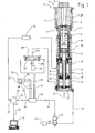
- Fig. 1. shows a preforming station 1 of a glass forming machine 2, in which it is e.g. may be a section of an I.S. glass forming machine.
- the preform station 1 has a preform bottom 3, preform halves 4 and 5, muzzle halfs 6 and 7 and a ram 8 on.
- the ram 8 is in in a known manner at the upper end of a piston rod 9 of a piston 10 attached.
- the piston 10 is in a cylinder 11 of a piston-cylinder unit 12 movable. Below the piston 10 is a feed space 13 and above the piston 10 a retreatment space 14.
- the piston 10th carries an actuating ring 15 for a ram position sensor 16, which in this case is designed according to EP 0 652 854 B1.
- the ram 8 is by a coaxial with the cylinder 11 guide cylinder 17 led.
- the guide cylinder 17 is also a spring 18th arranged at the vented feed space 13 and vented retreat area 14 the ram 8 in its axial loading position 19 shown in FIG ( Figure 2D).
- this loading position 19 dips an upper tip of the Press ram 8 straight in a mouth region of a preforming 20 on.
- first of the preform bottom 3 is removed, so that from above a glass gob in the Vorformaus fundamentalung 20 and on the Tip of the ram 8 can fall.
- the piston rod 9 is hollow and takes on a bottom 21 of the Cylinder 11 attached cooling air pipe 22.
- the cooling air pipe 22 is cooling air supplied for the ram 8 in the direction of arrow 23.
- the punch position sensor 16 is via a signal amplifier / signal evaluation unit 24 connected to a signal input 25 of a control circuit 26.
- the control circuit 26 is also bidirectionally via a line 30 with an input / output unit 31 connected.
- a signal output 32 of the control circuit 26 is connected via a line 33 to an input 34 of an electronic Control unit 35 connected.
- the electronic control unit 35 are from a timing control 28 via a line 57, a press punch feed signal 29 and via a line 58 a ram withdrawal signal 27 can be fed.
- the electronic control unit 35 controls via control lines 36 and 37 Electromagnets 59 and 60 of a proportional valve 38, which as 3-way / 3-position valve is formed.
- the proportional valve 38 is between a first pressure medium source 39 and a line 40 to the feed space 13th switched on.
- Another control line 41 of the electronic control unit 35 leads to a 3-way / 2-way valve 42 connected between a second source of pressure medium 43 and a line 44 to the withdrawal room 14 is turned on.
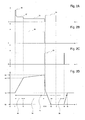
- FIG. 2B shows that provided by the timing controller 28 Punch feed signal 29 over time.
- Fig. 2C shows the pressure curve in the retraction space 14 over time.
- Fig. 2D gives the axial position of the ram 8 over time again.
- a pressing cycle is 45 registered.
- the press punch feed signal is generated 29 through the timing controller 28 in the electronic control unit 35 input, in turn, the proportional valve 38 in Fig. 1 to the right turns on.
- the first pressure medium source 39 with connected to the feed space 13.
- the proportional valve 38 initiates Pressure medium, in particular compressed air, according to the setpoint specifications As shown in FIG. 2A in the feed space 13 a.
- the plunger feed signal 29 At the end of the pressing t3 ends the plunger feed signal 29 and is the Proportional valve 38 fully switched through to the left. This will make the feed space 13 vented.
- the directional control valve 42 is down through and thereby the second pressure medium source 43, in particular a compressed air source, connected to the retraction space 14. This builds up As shown in FIG. 2C, a fourth pressure 53 in the retraction space 14 and pulls the Press ram 8 relatively quickly back to a time t4.
- the back pressure 54 can already before the time t6 at a time t7 be terminated as soon as the ram 8 in its reverse position 55 for Rest has come.
- FIG. 3 shows another embodiment of the proportional valve 38, which has: An actuatable by the electromagnets 59 and 60 in both switching directions Directional valve 61, a valve driver electronics 62, on the one hand via a control line 63 to the control unit 35 and on the other hand via one each Control line 64 and 65 is connected to the electromagnets 59, 60, and a pressure sensor 66, on the one hand via a branch line 67 with the directional control valve 61 with the feed space 13 connecting line 40 and on the other is connected via a signal line 68 to the valve driver electronics 62.
Landscapes
- Engineering & Computer Science (AREA)
- Chemical & Material Sciences (AREA)
- Mechanical Engineering (AREA)
- Manufacturing & Machinery (AREA)
- Materials Engineering (AREA)
- Organic Chemistry (AREA)
- Glass Compositions (AREA)
- Re-Forming, After-Treatment, Cutting And Transporting Of Glass Products (AREA)
- Blow-Moulding Or Thermoforming Of Plastics Or The Like (AREA)
- Press Drives And Press Lines (AREA)
- Control Of Presses (AREA)
- Casting Or Compression Moulding Of Plastics Or The Like (AREA)
- Injection Moulding Of Plastics Or The Like (AREA)
- Moulds For Moulding Plastics Or The Like (AREA)
Abstract
Description
Claims (14)
- Verfahren zum Antrieb eines Pressstempels (8) für eine Vorform (3 bis 7) einer Glasformmaschine (2) durch eine Kolben-Zylinder-Einheit (12) mit einem Vorschubraum (13) auf einer Seite eines Kolbens (10) und einem Rückzugsraum (14) auf der gegenüberliegenden Seite des Kolbens (10),
wobei der Vorschubraum (13) über ein durch eine elektronische Steuereinheit (35) ansteuerbares Proportionalventil (38) mit einer ersten Druckmediumquelle (39) verbindbar ist,
mit folgenden Schritten:gekennzeichnet durch folgende Schritte:(a) Zu einem Startzeitpunkt (t1) eines Presszyklus (45) wird durch das Proportionalventil (38) kurzzeitig Druckmedium mit einem verhältnismäßig hohen ersten Druck (46) in den Vorschubraum (13) geleitet, und(b) im Anschluss an Schritt (a) leitet das Proportionalventil (38) bis zu einem Pressende (t3) des Presszyklus (45) Druckmedium mit einem niedrigeren Druck (47,51) in den Vorschubraum (13),(A) Zum Startzeitpunkt (t1) befindet der Pressstempel (8) sich in einer Ladestellung (19), in welcher ein Glastropfen in die Vorform (4 bis 7) eingebracht wurde,(B) im Anschluss an den verhältnismäßig hohen ersten Druck (46) gemäß Schritt (a) wird durch das Proportionalventil (38) Druckmedium mit einem derart geregelten zweiten Druck (47) des niedrigeren Drucks (47,50) in den Vorschubraum (13) geleitet dass bei einem Pressbeginn (t2), bei dem der Pressstempel (8) eine Formausnehmung (20) der Vorform (3 bis 7) vollständig mit schmelzflüssigem Glas gefüllt hat, der Pressstempel (8) eine Pressanfangsstellung (48) erreicht,(C) während einer konstanten Pressdauer (50) vom Pressbeginn (t2) bis zum Pressende (t3), bei dem der Pressstempel (8) seine größte Eindringtiefe in die Vorform (3 bis 7) erreicht, wird durch das Proportionalventil (38) Druckmedium mit einem konstanten dritten Druck (51) des niedrigeren Drucks (47,51) in den Vorschubraum (13) geleitet, und(D) vom Startzeitpunkt (t1) bis zum Pressende (t3) wird der Rückzugsraum (14) drucklos geschaltet. - Verfahren nach Anspruch 1,
dadurch gekennzeichnet, dass die axiale Stellung des Pressstempels (8) abgetastet (15,16) und ein entsprechendes elektrisches Stellungssignal gewonnen wird,
und dass das Stellungssignal zur Regelung des zweiten Drucks (47) herangezogen wird. - Verfahren nach Anspruch 1 oder 2,
dadurch gekennzeichnet, dass der dritte Druck (51) höher als der zweite Druck (47) gewählt wird. - Verfahren nach Anspruch 1 oder 2,
dadurch gekennzeichnet, dass der dritte Druck (51) niedriger als der zweite Druck (47) gewählt wird. - Verfahren nach einem der Ansprüche 1 bis 4,
dadurch gekennzeichnet, dass am Pressende (t3) der Vorschubraum (13) drucklos geschaltet und der Rückzugsraum (14) mit Druckmedium mit einem vierten Druck (53) beaufschlagt wird,
und dass der vierte Druck (53) aufrechterhalten wird, bis der Pressstempel (8) sich zunächst über die Ladestellung (19) hinaus in eine Umkehrstellung (55) zurückbewegt hat und anschließend während einer Umkehrdauer (56) in der Umkehrstellung (55) verblieben ist. - Verfahren nach Anspruch 5,
dadurch gekennzeichnet, dass der vierte Druck (53) konstant gehalten wird. - Verfahren nach Anspruch 5 oder 6,
dadurch gekennzeichnet, dass vor dem Zeitpunkt (t5), zu dem der Pressstempel (8) seine Umkehrstellung (55) erreicht, durch das Proportionalventil (38) Druckmedium mit einem Gegendruck (54) in den Vorschubraum (13) geleitet wird,
und dass der Gegendruck (54) bis zu einem Zeitpunkt (t7) aufrechterhalten wird, zu dem der Pressstempel (8) in seiner Umkehrstellung (55) zur Ruhe gekommen ist. - Verfahren nach einem der Ansprüche 5 bis 7,
dadurch gekennzeichnet, dass am Ende (t6) der Umkehrdauer (56) der Rückzugsraum (14) drucklos geschaltet wird, so dass der Pressstempel (8) unter der Wirkung einer Feder (18) aus seiner Umkehrstellung (55) in seine Ladestellung (19) zurückkehren und damit den Presszyklus (45) beenden kann. - Vorrichtung zum Antrieb eines Pressstempels (8) für eine Vorform (3 bis 7) einer Glasformmaschine (2) durch eine Kolben-Zylinder-Einheit (12) mit einem Vorschubraum (13) auf einer Seite eines Kolbens (10) und einem Rückzugsraum (14) auf der gegenüberliegenden Seite des Kolbens (10),
wobei der Vorschubraum (13) über ein durch eine elektronische Steuereinheit (35) ansteuerbares Proportionalventil (38) mit einer ersten Druckmediumquelle (39) verbindbar ist,
dadurch gekennzeichnet, dass die Steuereinheit (35) mit einer Regelschaltung (26) verbunden ist,
dass die Regelschaltung (26) bidirektional mit einer Eingabe/Ausgabeeinheit (31) verbunden ist,
und dass mit einem Signaleingang (25) der Regelschaltung (26) über eine Signalverstärker/Signalauswerteeinheit (24) ein Signalausgang eines die axiale Stellung des Pressstempels (8) abtastenden Sensors (15,16) verbunden ist. - Vorrichtung nach Anspruch 9,
dadurch gekennzeichnet, dass einem Signaleingang der Steuereinheit (35) ein aus einer Zeitablaufsteuerung (28) generiertes Pressstempel-Vorschubsignal (29) zuführbar ist. - Vorrichtung nach Anspruch 9 oder 10,
dadurch gekennzeichnet, dass einem Signaleingang der Steuereinheit (35) ein aus einer Zeitablaufsteuerung (28) generiertes Pressstempel-Rückzugssignal (27) zuführbar ist. - Vorrichtung nach einem der Ansprüche 9 bis 11,
dadurch gekennzeichnet, dass Elektromagnete (59,60) des Proportionalventils (38) über Steuerleitungen (36,37) durch die Steuereinheit (35) steuerbar sind. - Vorrichtung nach einem der Ansprüche 9 bis 11,
dadurch gekennzeichnet, dass das Proportionalventil (38) aufweist:(a) Ein durch Elektromagnete (59,60) in beide Schaltrichtungen betätigbares Wegeventil (61),(b) eine Ventiltreiberelektronik (62), die einerseits über eine Steuerleitung (63) mit der Steuereinheit (35) und andererseits über je eine Steuerleitung (64;65) mit den Elektromagneten (59,60) verbunden ist, und(c) einen Drucksensor (66), der einerseits über eine Stichleitung (67) mit einer das Wegeventil (61) mit dem Vorschubraum (13) verbindenden Leitung (40) und andererseits über eine Signalleitung (68) mit der Ventiltreiberelektronik (62) verbunden ist. - Vorrichtung nach einem der Ansprüche 9 bis 13,
dadurch gekennzeichnet, dass der Rückzugsraum (14) über ein durch die elektronische Steuereinheit (35) ansteuerbares Wegeventil (42) wahlweise mit einer zweiten Druckmediumquelle (43) verbindbar oder drucklos schaltbar ist.
Priority Applications (1)
| Application Number | Priority Date | Filing Date | Title |
|---|---|---|---|
| PL04006619T PL1466871T3 (pl) | 2003-04-11 | 2004-03-19 | Sposób i urządzenie do napędu stempla tłocznego maszyny fomującej do szkła |
Applications Claiming Priority (2)
| Application Number | Priority Date | Filing Date | Title |
|---|---|---|---|
| DE10316600 | 2003-04-11 | ||
| DE10316600A DE10316600A1 (de) | 2003-04-11 | 2003-04-11 | Verfahren und Vorrichtung zum Antrieb eines Pressstempels einer Glasformmaschine |
Publications (3)
| Publication Number | Publication Date |
|---|---|
| EP1466871A2 true EP1466871A2 (de) | 2004-10-13 |
| EP1466871A3 EP1466871A3 (de) | 2006-06-28 |
| EP1466871B1 EP1466871B1 (de) | 2009-04-22 |
Family
ID=32864439
Family Applications (1)
| Application Number | Title | Priority Date | Filing Date |
|---|---|---|---|
| EP04006619A Expired - Lifetime EP1466871B1 (de) | 2003-04-11 | 2004-03-19 | Verfahren und Vorrichtung zum Antrieb eines Pressstempels einer Glasformmaschine |
Country Status (6)
| Country | Link |
|---|---|
| EP (1) | EP1466871B1 (de) |
| AT (1) | ATE429409T1 (de) |
| DE (2) | DE10316600A1 (de) |
| ES (1) | ES2324409T3 (de) |
| PL (1) | PL1466871T3 (de) |
| PT (1) | PT1466871E (de) |
Cited By (4)
| Publication number | Priority date | Publication date | Assignee | Title |
|---|---|---|---|---|
| EP1681275A1 (de) * | 2005-01-07 | 2006-07-19 | Gps Glasproduktions-Service Gmbh | Vor- bzw. Fertigform einer Glasmaschine |
| EP2230220A1 (de) * | 2009-03-12 | 2010-09-22 | Gps Glasproduktions-Service Gmbh | Pegelmechanismus einer Glasmaschine |
| EP2570393A1 (de) | 2011-09-14 | 2013-03-20 | Emhart Glass S.A. | Haltezeitsteuerungsverfahren und System für eine Glaswarenbildungsmaschine |
| WO2016202429A1 (de) * | 2015-06-17 | 2016-12-22 | Heye International Gmbh | Anordnung zur darstellung des vakuumbetriebs im formgebungsprozess einer glasformmaschine |
Families Citing this family (2)
| Publication number | Priority date | Publication date | Assignee | Title |
|---|---|---|---|---|
| DE102004011647A1 (de) * | 2004-03-10 | 2005-09-29 | Heye International Gmbh | Verfahren und Vorrichtung zur Regelung der Glastropfenmasse bei der Herstellung von Hohlglasbehältern |
| US10618831B2 (en) | 2018-01-10 | 2020-04-14 | Owens-Brockway Glass Container Inc. | Parison plunger actuation |
Citations (3)
| Publication number | Priority date | Publication date | Assignee | Title |
|---|---|---|---|---|
| EP0691940B1 (de) | 1993-04-01 | 1997-05-02 | Emhart Glass Machinery Investments Inc. | Steuerung von pungers in glasformmaschinen |
| EP0802167A2 (de) | 1996-04-18 | 1997-10-22 | Emhart Glass Machinery Investments Inc. | Plunjervorrichtung |
| EP1002960A2 (de) | 1998-11-18 | 2000-05-24 | Gps Glasproduktions-Service Gmbh | Pressdruckregelvorrichtung für einen Antriebszylinder eines Werkzeugs oder Werkzeugteils einer IS-Glasmaschine |
Family Cites Families (7)
| Publication number | Priority date | Publication date | Assignee | Title |
|---|---|---|---|---|
| DE3401465C1 (de) * | 1984-01-18 | 1985-01-31 | Fa. Hermann Heye, 3063 Obernkirchen | Wegaufnehmer fuer den Positionsnachweis eines Pressstempels |
| GB2159813B (en) * | 1984-06-06 | 1987-12-31 | Emhart Ind | Forming a gob of molten glass into a parison |
| US5236485A (en) * | 1986-09-30 | 1993-08-17 | Manfred Leweringhause | Process and device for shaping a gob |
| US4867778A (en) * | 1988-02-05 | 1989-09-19 | Emhart Industries, Inc. | Individual section glass forming machine |
| DE9404164U1 (de) * | 1993-05-27 | 1994-05-19 | Fa. Hermann Heye, 31683 Obernkirchen | Wegaufnehmer für den Positionsnachweis eines Preßstempels |
| US6050172A (en) * | 1997-04-04 | 2000-04-18 | Emhart Glass S.A. | Pneumatically operated mechanism |
| IT1319860B1 (it) * | 2000-02-22 | 2003-11-03 | Bottero Spa | Metodo per la formatura di articoli di vetro cavi, e macchina diformatura utilizzante tale metodo |
-
2003
- 2003-04-11 DE DE10316600A patent/DE10316600A1/de not_active Ceased
-
2004
- 2004-03-19 PL PL04006619T patent/PL1466871T3/pl unknown
- 2004-03-19 PT PT04006619T patent/PT1466871E/pt unknown
- 2004-03-19 AT AT04006619T patent/ATE429409T1/de active
- 2004-03-19 EP EP04006619A patent/EP1466871B1/de not_active Expired - Lifetime
- 2004-03-19 ES ES04006619T patent/ES2324409T3/es not_active Expired - Lifetime
- 2004-03-19 DE DE502004009381T patent/DE502004009381D1/de not_active Expired - Lifetime
Patent Citations (3)
| Publication number | Priority date | Publication date | Assignee | Title |
|---|---|---|---|---|
| EP0691940B1 (de) | 1993-04-01 | 1997-05-02 | Emhart Glass Machinery Investments Inc. | Steuerung von pungers in glasformmaschinen |
| EP0802167A2 (de) | 1996-04-18 | 1997-10-22 | Emhart Glass Machinery Investments Inc. | Plunjervorrichtung |
| EP1002960A2 (de) | 1998-11-18 | 2000-05-24 | Gps Glasproduktions-Service Gmbh | Pressdruckregelvorrichtung für einen Antriebszylinder eines Werkzeugs oder Werkzeugteils einer IS-Glasmaschine |
Cited By (7)
| Publication number | Priority date | Publication date | Assignee | Title |
|---|---|---|---|---|
| EP1681275A1 (de) * | 2005-01-07 | 2006-07-19 | Gps Glasproduktions-Service Gmbh | Vor- bzw. Fertigform einer Glasmaschine |
| EP2230220A1 (de) * | 2009-03-12 | 2010-09-22 | Gps Glasproduktions-Service Gmbh | Pegelmechanismus einer Glasmaschine |
| EP2570393A1 (de) | 2011-09-14 | 2013-03-20 | Emhart Glass S.A. | Haltezeitsteuerungsverfahren und System für eine Glaswarenbildungsmaschine |
| US8561428B2 (en) | 2011-09-14 | 2013-10-22 | Emhart Glass S.A. | Dwell time control method and system with automatic pressure switch point adjustment |
| US9038420B2 (en) | 2011-09-14 | 2015-05-26 | Emhart Glass S.A. | Dwell time control system and method with automatic pressure switch point adjustment |
| WO2016202429A1 (de) * | 2015-06-17 | 2016-12-22 | Heye International Gmbh | Anordnung zur darstellung des vakuumbetriebs im formgebungsprozess einer glasformmaschine |
| US10836670B2 (en) | 2015-06-17 | 2020-11-17 | Heye International Gmbh | Arrangement for realizing the vacuum operation in the moulding process of a glass moulding machine |
Also Published As
| Publication number | Publication date |
|---|---|
| EP1466871B1 (de) | 2009-04-22 |
| EP1466871A3 (de) | 2006-06-28 |
| ATE429409T1 (de) | 2009-05-15 |
| PT1466871E (pt) | 2009-06-04 |
| ES2324409T3 (es) | 2009-08-06 |
| DE10316600A1 (de) | 2004-11-04 |
| DE502004009381D1 (de) | 2009-06-04 |
| PL1466871T3 (pl) | 2009-09-30 |
Similar Documents
| Publication | Publication Date | Title |
|---|---|---|
| EP0280056B1 (de) | Hydraulische Kaltfliesspresse | |
| DE68913647T2 (de) | Pneumatisches Gesenkpolster. | |
| DE60313557T2 (de) | Doppeltwirkende, hydraulische Presse | |
| DE3718961C2 (de) | ||
| EP0776261B2 (de) | Vorrichtung zum zusammenschweissen wenigstens zweier teile und mit dieser vorrichtung durchführbares verfahren | |
| EP4281282B1 (de) | Hydraulische umformmaschine zum pressen von werkstücken, insbesondere schmiedehammer, und verfahren zum betreiben einer hydraulischen umformmaschine, insbesondere eines schmiedehammers | |
| DE2458233C3 (de) | Vorrichtung zum Herstellen von Gläsern nach dem Külbeldrehverfahren | |
| EP1466871B1 (de) | Verfahren und Vorrichtung zum Antrieb eines Pressstempels einer Glasformmaschine | |
| EP1129039A1 (de) | Verfahren und vorrichtung zum pressen eines külbels | |
| EP2067544A1 (de) | Verfahren und Werkzeugmaschine zum Bearbeiten von Werkstücken | |
| DE60110291T2 (de) | Verfahren zur Herstellung von Hohlglaswaren und Maschine zur Ausführung dieses Verfahren | |
| DE2805187C2 (de) | Gesenkschmiedepresse | |
| WO2000062956A1 (de) | Verfahren zur massivumformung von axial-symmetrischen metallischen bauteilen | |
| EP2384833B1 (de) | Niederhalterregelung bei der Herstellung von Dosenkörpern | |
| EP1599424B1 (de) | Verfahren und vorrichtung zur regelung der glastropfenmasse bei der herstellung von hohlglasbehältern | |
| DE102023105367A1 (de) | Hydraulische Umformmaschine zur Werkstückumformung, Hydrauliksteuereinheit und Verfahren zur Steuerung eines Hydraulikzylinders einer hydraulischen Umformmaschine | |
| DE2432774A1 (de) | Verfahren zur steuerung des vor- und ruecklaufes eines werkzeuges an einer bearbeitungsmaschine und vorrichtung zur ausfuehrung des verfahrens | |
| EP0284903B1 (de) | Kolbenpresse | |
| DE3633137C2 (de) | ||
| DE3907702C2 (de) | ||
| DE102023113473B4 (de) | Hydraulische Umformmaschine zur Werkstückumformung, Hydrauliksteuereinheit und Verfahren zur Steuerung eines Hydraulikzylinders einer hydraulischen Umformmaschine | |
| DE1807650A1 (de) | Vorrichtung an Formwerkzeugen u.dgl.zum Antrieb und zur Steuerung der Abgabe einer Schmier- und Reinigungsfluessigkeit | |
| DE10023164B4 (de) | Bügelmaschine | |
| AT205687B (de) | Verfahren zur Herstellung und zur weiteren Bearbeitung des Kolbens einer Kathodenstrahlröhre | |
| DE3718159A1 (de) | Ziehapparat an pressen |
Legal Events
| Date | Code | Title | Description |
|---|---|---|---|
| PUAI | Public reference made under article 153(3) epc to a published international application that has entered the european phase |
Free format text: ORIGINAL CODE: 0009012 |
|
| AK | Designated contracting states |
Kind code of ref document: A2 Designated state(s): AT BE BG CH CY CZ DE DK EE ES FI FR GB GR HU IE IT LI LU MC NL PL PT RO SE SI SK TR |
|
| AX | Request for extension of the european patent |
Extension state: AL LT LV MK |
|
| PUAL | Search report despatched |
Free format text: ORIGINAL CODE: 0009013 |
|
| AK | Designated contracting states |
Kind code of ref document: A3 Designated state(s): AT BE BG CH CY CZ DE DK EE ES FI FR GB GR HU IE IT LI LU MC NL PL PT RO SE SI SK TR |
|
| AX | Request for extension of the european patent |
Extension state: AL LT LV MK |
|
| 17P | Request for examination filed |
Effective date: 20061010 |
|
| 17Q | First examination report despatched |
Effective date: 20070112 |
|
| AKX | Designation fees paid |
Designated state(s): AT BE BG CH CY CZ DE DK EE ES FI FR GB GR HU IE IT LI LU MC NL PL PT RO SE SI SK TR |
|
| GRAP | Despatch of communication of intention to grant a patent |
Free format text: ORIGINAL CODE: EPIDOSNIGR1 |
|
| GRAS | Grant fee paid |
Free format text: ORIGINAL CODE: EPIDOSNIGR3 |
|
| GRAA | (expected) grant |
Free format text: ORIGINAL CODE: 0009210 |
|
| AK | Designated contracting states |
Kind code of ref document: B1 Designated state(s): AT BE BG CH CY CZ DE DK EE ES FI FR GB GR HU IE IT LI LU MC NL PL PT RO SE SI SK TR |
|
| REG | Reference to a national code |
Ref country code: GB Ref legal event code: FG4D Free format text: NOT ENGLISH |
|
| REG | Reference to a national code |
Ref country code: CH Ref legal event code: EP |
|
| REG | Reference to a national code |
Ref country code: IE Ref legal event code: FG4D |
|
| REF | Corresponds to: |
Ref document number: 502004009381 Country of ref document: DE Date of ref document: 20090604 Kind code of ref document: P |
|
| REG | Reference to a national code |
Ref country code: PT Ref legal event code: SC4A Free format text: AVAILABILITY OF NATIONAL TRANSLATION Effective date: 20090527 |
|
| REG | Reference to a national code |
Ref country code: ES Ref legal event code: FG2A Ref document number: 2324409 Country of ref document: ES Kind code of ref document: T3 |
|
| REG | Reference to a national code |
Ref country code: SE Ref legal event code: TRGR |
|
| REG | Reference to a national code |
Ref country code: PL Ref legal event code: T3 |
|
| PG25 | Lapsed in a contracting state [announced via postgrant information from national office to epo] |
Ref country code: FI Free format text: LAPSE BECAUSE OF FAILURE TO SUBMIT A TRANSLATION OF THE DESCRIPTION OR TO PAY THE FEE WITHIN THE PRESCRIBED TIME-LIMIT Effective date: 20090422 |
|
| PG25 | Lapsed in a contracting state [announced via postgrant information from national office to epo] |
Ref country code: SI Free format text: LAPSE BECAUSE OF FAILURE TO SUBMIT A TRANSLATION OF THE DESCRIPTION OR TO PAY THE FEE WITHIN THE PRESCRIBED TIME-LIMIT Effective date: 20090422 |
|
| REG | Reference to a national code |
Ref country code: IE Ref legal event code: FD4D |
|
| PG25 | Lapsed in a contracting state [announced via postgrant information from national office to epo] |
Ref country code: EE Free format text: LAPSE BECAUSE OF FAILURE TO SUBMIT A TRANSLATION OF THE DESCRIPTION OR TO PAY THE FEE WITHIN THE PRESCRIBED TIME-LIMIT Effective date: 20090422 Ref country code: CZ Free format text: LAPSE BECAUSE OF FAILURE TO SUBMIT A TRANSLATION OF THE DESCRIPTION OR TO PAY THE FEE WITHIN THE PRESCRIBED TIME-LIMIT Effective date: 20090422 Ref country code: RO Free format text: LAPSE BECAUSE OF FAILURE TO SUBMIT A TRANSLATION OF THE DESCRIPTION OR TO PAY THE FEE WITHIN THE PRESCRIBED TIME-LIMIT Effective date: 20090422 Ref country code: DK Free format text: LAPSE BECAUSE OF FAILURE TO SUBMIT A TRANSLATION OF THE DESCRIPTION OR TO PAY THE FEE WITHIN THE PRESCRIBED TIME-LIMIT Effective date: 20090422 Ref country code: IE Free format text: LAPSE BECAUSE OF FAILURE TO SUBMIT A TRANSLATION OF THE DESCRIPTION OR TO PAY THE FEE WITHIN THE PRESCRIBED TIME-LIMIT Effective date: 20090422 |
|
| PG25 | Lapsed in a contracting state [announced via postgrant information from national office to epo] |
Ref country code: SK Free format text: LAPSE BECAUSE OF FAILURE TO SUBMIT A TRANSLATION OF THE DESCRIPTION OR TO PAY THE FEE WITHIN THE PRESCRIBED TIME-LIMIT Effective date: 20090422 |
|
| PLBE | No opposition filed within time limit |
Free format text: ORIGINAL CODE: 0009261 |
|
| STAA | Information on the status of an ep patent application or granted ep patent |
Free format text: STATUS: NO OPPOSITION FILED WITHIN TIME LIMIT |
|
| 26N | No opposition filed |
Effective date: 20100125 |
|
| PG25 | Lapsed in a contracting state [announced via postgrant information from national office to epo] |
Ref country code: BG Free format text: LAPSE BECAUSE OF FAILURE TO SUBMIT A TRANSLATION OF THE DESCRIPTION OR TO PAY THE FEE WITHIN THE PRESCRIBED TIME-LIMIT Effective date: 20090722 |
|
| BERE | Be: lapsed |
Owner name: HEYE INTERNATIONAL G.M.B.H. Effective date: 20100331 |
|
| PG25 | Lapsed in a contracting state [announced via postgrant information from national office to epo] |
Ref country code: GR Free format text: LAPSE BECAUSE OF FAILURE TO SUBMIT A TRANSLATION OF THE DESCRIPTION OR TO PAY THE FEE WITHIN THE PRESCRIBED TIME-LIMIT Effective date: 20090723 Ref country code: MC Free format text: LAPSE BECAUSE OF NON-PAYMENT OF DUE FEES Effective date: 20100331 |
|
| REG | Reference to a national code |
Ref country code: CH Ref legal event code: PL |
|
| PG25 | Lapsed in a contracting state [announced via postgrant information from national office to epo] |
Ref country code: CH Free format text: LAPSE BECAUSE OF NON-PAYMENT OF DUE FEES Effective date: 20100331 Ref country code: LI Free format text: LAPSE BECAUSE OF NON-PAYMENT OF DUE FEES Effective date: 20100331 Ref country code: BE Free format text: LAPSE BECAUSE OF NON-PAYMENT OF DUE FEES Effective date: 20100331 |
|
| REG | Reference to a national code |
Ref country code: DE Ref legal event code: R082 Ref document number: 502004009381 Country of ref document: DE Representative=s name: SOBISCH & KRAMM, DE |
|
| PG25 | Lapsed in a contracting state [announced via postgrant information from national office to epo] |
Ref country code: CY Free format text: LAPSE BECAUSE OF FAILURE TO SUBMIT A TRANSLATION OF THE DESCRIPTION OR TO PAY THE FEE WITHIN THE PRESCRIBED TIME-LIMIT Effective date: 20090422 |
|
| PG25 | Lapsed in a contracting state [announced via postgrant information from national office to epo] |
Ref country code: LU Free format text: LAPSE BECAUSE OF NON-PAYMENT OF DUE FEES Effective date: 20100319 Ref country code: HU Free format text: LAPSE BECAUSE OF FAILURE TO SUBMIT A TRANSLATION OF THE DESCRIPTION OR TO PAY THE FEE WITHIN THE PRESCRIBED TIME-LIMIT Effective date: 20091023 |
|
| REG | Reference to a national code |
Ref country code: FR Ref legal event code: PLFP Year of fee payment: 13 |
|
| REG | Reference to a national code |
Ref country code: FR Ref legal event code: PLFP Year of fee payment: 14 |
|
| REG | Reference to a national code |
Ref country code: FR Ref legal event code: PLFP Year of fee payment: 15 |
|
| REG | Reference to a national code |
Ref country code: DE Ref legal event code: R082 Ref document number: 502004009381 Country of ref document: DE Representative=s name: MICHALSKI HUETTERMANN & PARTNER PATENTANWAELTE, DE |
|
| PGFP | Annual fee paid to national office [announced via postgrant information from national office to epo] |
Ref country code: GB Payment date: 20220321 Year of fee payment: 19 Ref country code: DE Payment date: 20220329 Year of fee payment: 19 Ref country code: AT Payment date: 20220322 Year of fee payment: 19 |
|
| PGFP | Annual fee paid to national office [announced via postgrant information from national office to epo] |
Ref country code: TR Payment date: 20220315 Year of fee payment: 19 Ref country code: SE Payment date: 20220321 Year of fee payment: 19 Ref country code: PT Payment date: 20220310 Year of fee payment: 19 Ref country code: PL Payment date: 20220311 Year of fee payment: 19 Ref country code: NL Payment date: 20220321 Year of fee payment: 19 Ref country code: IT Payment date: 20220322 Year of fee payment: 19 Ref country code: FR Payment date: 20220322 Year of fee payment: 19 |
|
| PGFP | Annual fee paid to national office [announced via postgrant information from national office to epo] |
Ref country code: ES Payment date: 20220525 Year of fee payment: 19 |
|
| REG | Reference to a national code |
Ref country code: DE Ref legal event code: R119 Ref document number: 502004009381 Country of ref document: DE |
|
| PG25 | Lapsed in a contracting state [announced via postgrant information from national office to epo] |
Ref country code: PT Free format text: LAPSE BECAUSE OF NON-PAYMENT OF DUE FEES Effective date: 20230919 |
|
| REG | Reference to a national code |
Ref country code: SE Ref legal event code: EUG |
|
| REG | Reference to a national code |
Ref country code: NL Ref legal event code: MM Effective date: 20230401 |
|
| REG | Reference to a national code |
Ref country code: AT Ref legal event code: MM01 Ref document number: 429409 Country of ref document: AT Kind code of ref document: T Effective date: 20230319 |
|
| GBPC | Gb: european patent ceased through non-payment of renewal fee |
Effective date: 20230319 |
|
| PG25 | Lapsed in a contracting state [announced via postgrant information from national office to epo] |
Ref country code: NL Free format text: LAPSE BECAUSE OF NON-PAYMENT OF DUE FEES Effective date: 20230401 |
|
| PG25 | Lapsed in a contracting state [announced via postgrant information from national office to epo] |
Ref country code: GB Free format text: LAPSE BECAUSE OF NON-PAYMENT OF DUE FEES Effective date: 20230319 |
|
| PG25 | Lapsed in a contracting state [announced via postgrant information from national office to epo] |
Ref country code: SE Free format text: LAPSE BECAUSE OF NON-PAYMENT OF DUE FEES Effective date: 20230320 Ref country code: GB Free format text: LAPSE BECAUSE OF NON-PAYMENT OF DUE FEES Effective date: 20230319 Ref country code: FR Free format text: LAPSE BECAUSE OF NON-PAYMENT OF DUE FEES Effective date: 20230331 Ref country code: DE Free format text: LAPSE BECAUSE OF NON-PAYMENT OF DUE FEES Effective date: 20231003 Ref country code: AT Free format text: LAPSE BECAUSE OF NON-PAYMENT OF DUE FEES Effective date: 20230319 |
|
| PG25 | Lapsed in a contracting state [announced via postgrant information from national office to epo] |
Ref country code: IT Free format text: LAPSE BECAUSE OF NON-PAYMENT OF DUE FEES Effective date: 20230319 |
|
| REG | Reference to a national code |
Ref country code: ES Ref legal event code: FD2A Effective date: 20240430 |
|
| PG25 | Lapsed in a contracting state [announced via postgrant information from national office to epo] |
Ref country code: ES Free format text: LAPSE BECAUSE OF NON-PAYMENT OF DUE FEES Effective date: 20230320 |
|
| PG25 | Lapsed in a contracting state [announced via postgrant information from national office to epo] |
Ref country code: ES Free format text: LAPSE BECAUSE OF NON-PAYMENT OF DUE FEES Effective date: 20230320 |
|
| PG25 | Lapsed in a contracting state [announced via postgrant information from national office to epo] |
Ref country code: PL Free format text: LAPSE BECAUSE OF NON-PAYMENT OF DUE FEES Effective date: 20230319 |
|
| PG25 | Lapsed in a contracting state [announced via postgrant information from national office to epo] |
Ref country code: PL Free format text: LAPSE BECAUSE OF NON-PAYMENT OF DUE FEES Effective date: 20230319 |