EP1467124A2 - Kugelspindelantrieb für Flugzeugsteuerflächen - Google Patents
Kugelspindelantrieb für Flugzeugsteuerflächen Download PDFInfo
- Publication number
- EP1467124A2 EP1467124A2 EP03425554A EP03425554A EP1467124A2 EP 1467124 A2 EP1467124 A2 EP 1467124A2 EP 03425554 A EP03425554 A EP 03425554A EP 03425554 A EP03425554 A EP 03425554A EP 1467124 A2 EP1467124 A2 EP 1467124A2
- Authority
- EP
- European Patent Office
- Prior art keywords
- actuator
- auxiliary portion
- screw
- secondary body
- thread
- Prior art date
- Legal status (The legal status is an assumption and is not a legal conclusion. Google has not performed a legal analysis and makes no representation as to the accuracy of the status listed.)
- Withdrawn
Links
- 238000010168 coupling process Methods 0.000 claims description 5
- 238000005859 coupling reaction Methods 0.000 claims description 5
- 239000000463 material Substances 0.000 claims description 5
- 239000003381 stabilizer Substances 0.000 description 5
- 230000008878 coupling Effects 0.000 description 3
- 230000009471 action Effects 0.000 description 2
- 230000000903 blocking effect Effects 0.000 description 2
- 230000007257 malfunction Effects 0.000 description 2
- 230000007246 mechanism Effects 0.000 description 2
- 230000009467 reduction Effects 0.000 description 2
- 230000008859 change Effects 0.000 description 1
- 230000037431 insertion Effects 0.000 description 1
- 238000003780 insertion Methods 0.000 description 1
- 210000000056 organ Anatomy 0.000 description 1
- 238000011084 recovery Methods 0.000 description 1
- 230000008439 repair process Effects 0.000 description 1
- 238000000926 separation method Methods 0.000 description 1
- 125000006850 spacer group Chemical group 0.000 description 1
Images

Classifications
-
- F—MECHANICAL ENGINEERING; LIGHTING; HEATING; WEAPONS; BLASTING
- F16—ENGINEERING ELEMENTS AND UNITS; GENERAL MEASURES FOR PRODUCING AND MAINTAINING EFFECTIVE FUNCTIONING OF MACHINES OR INSTALLATIONS; THERMAL INSULATION IN GENERAL
- F16H—GEARING
- F16H25/00—Gearings comprising primarily only cams, cam-followers and screw-and-nut mechanisms
- F16H25/18—Gearings comprising primarily only cams, cam-followers and screw-and-nut mechanisms for conveying or interconverting oscillating or reciprocating motions
- F16H25/20—Screw mechanisms
- F16H25/205—Screw mechanisms comprising alternate power paths, e.g. for fail safe back-up
-
- F—MECHANICAL ENGINEERING; LIGHTING; HEATING; WEAPONS; BLASTING
- F16—ENGINEERING ELEMENTS AND UNITS; GENERAL MEASURES FOR PRODUCING AND MAINTAINING EFFECTIVE FUNCTIONING OF MACHINES OR INSTALLATIONS; THERMAL INSULATION IN GENERAL
- F16H—GEARING
- F16H25/00—Gearings comprising primarily only cams, cam-followers and screw-and-nut mechanisms
- F16H25/18—Gearings comprising primarily only cams, cam-followers and screw-and-nut mechanisms for conveying or interconverting oscillating or reciprocating motions
- F16H25/20—Screw mechanisms
- F16H25/24—Elements essential to such mechanisms, e.g. screws, nuts
- F16H25/2472—Safety nuts
-
- F—MECHANICAL ENGINEERING; LIGHTING; HEATING; WEAPONS; BLASTING
- F16—ENGINEERING ELEMENTS AND UNITS; GENERAL MEASURES FOR PRODUCING AND MAINTAINING EFFECTIVE FUNCTIONING OF MACHINES OR INSTALLATIONS; THERMAL INSULATION IN GENERAL
- F16H—GEARING
- F16H25/00—Gearings comprising primarily only cams, cam-followers and screw-and-nut mechanisms
- F16H25/18—Gearings comprising primarily only cams, cam-followers and screw-and-nut mechanisms for conveying or interconverting oscillating or reciprocating motions
- F16H25/20—Screw mechanisms
- F16H25/22—Screw mechanisms with balls, rollers, or similar members between the co-operating parts; Elements essential to the use of such members
- F16H25/2204—Screw mechanisms with balls, rollers, or similar members between the co-operating parts; Elements essential to the use of such members with balls
Definitions
- the present invention relates to a ball screw actuator for aircraft control surfaces.
- Aircraft control surfaces are commanded by appropriate actuators able to move them between two extreme positions, in such a way as to make the surfaces assume operative configurations suitable for specific phases of flight.
- actuators are used to command the flaps installed on the trailing edge of a wing or to control the elevators mounted on the tail empennage.
- Ball screw actuators are known which are constituted by a lead screw set in rotation about its own longitudinal axis by a motor and associated to a tubular body, known in the specific art as lead nut, mounted coaxially on the screw itself.
- the lead nut is cinematically connected to the control surface whilst the screw is mounted integrally on the load bearing structure of the aircraft.
- the lead nut which is prevented from rotating, has on its own inner surface appropriate seats for a plurality of balls able to rotate on themselves and to slide in the throat of the thread of the lead nut.
- the rotation of the lead screw determines, by means of the coupling provided by the screws, the sliding of the lead nut along the longitudinal axis of the screw and the consequent motion of the control surface.
- actuators in which the screw is connected to the control surface and translates, whilst the lead nut is connected to the structure and rotates.
- auxiliary lead nut connected to the main one, which becomes operative when a malfunction occurs in the main lead nut itself.
- the auxiliary lead nut serves as a safety device.
- auxiliary ball lead nuts are known which are structurally similar to the primary ones. Although this type of solution assures control even after the rupture of the main lead nut, it should be noted that auxiliary lead nuts can be subject to the same type of failure as the primary ones.
- inverse thread auxiliary lead nuts constituted by a tubular portion connected to the main lead nut which has on its own inner surface, facing the lead nut, a thread with reversed shape relative to the thread of the screw.
- the balls maintain the reversed thread of the auxiliary lead nut at a determined distance from the thread of the screw and the tubular portion of the is perfectly coaxial to the longitudinal axis of the screw.
- both lead nuts lose the coaxial positioning relative to the shaft of the screw and the inverse thread of the auxiliary lead nut is engaged in the throat of the thread of the lead nut.
- a first type of inverse thread auxiliary lead nut is made of frictionless material which slides in the throat of the thread of the screw and serves the function of the balls for a certain fraction of the required working life.
- the main drawback of such a solution is that the duration of the frictionless inverse thread cannot be estimated correctly; the thread can be damaged rapidly and lead to the lack of structural connection between the aforementioned components.
- Auxiliary lead nuts are known with high friction coefficient which causes the seizure of the auxiliary lead nut on the screw and the consequent locking of the main lead nut and of the control surfaces connected thereto.
- the control surfaces are no longer controllable, but remain motionless in a determined position, allowing in any case to control the aircraft to a landing.
- the seizure of the inverse thread on the screw occurs during the rotation thereof.
- the torque imparted to the screw by the motor is contrasted by the friction torque imparted by the inverse thread under the action of the external load. Consequently, the load at which the seizure occurs may be very high and not included in the flight envelope of the aircraft.
- a device for blocking a ball screw actuator which comprises a sensor mechanism, able to detect a malfunction of the primary lead nut, and means for blocking the screw relative to the primary lead nut in case of failure.
- the locking means are defined by a pair of disk-shaped elements which, activated by the sensor mechanism, are thrust by respective springs between the throat of the thread of the screw and an inner surface of a containment body of the screw itself. This device is formed by a multiplicity of elements easily subject to rupture which cannot assure the necessary safety margin.
- the document US 4 644 811 has a ball screw actuator provided with a free wheel end stop device.
- the actuator comprises a ball screw threaded on a predominant portion except at one of its ends.
- the screw is inserted in a main lead nut, provided with balls engaged on the thread of the screw, and in a secondary lead nut, integral with the main one and driven thereby.
- the secondary lead nut is coupled with the main one by means of a retaining pin and a thrust bearing interposed axially.
- An aim of the present invention is to solve the problems noted in the prior art, proposing a ball screw actuator for aircraft control surfaces able to overcome the aforementioned drawbacks.
- an aim of the present invention is to provide a ball screw actuator for aircraft control surfaces that assures the ability of controlling the aircraft even in case of failure of the main lead nut.
- Another aim of the present invention is to propose a simple and reliable ball screw actuator for aircraft control surfaces.
- a further aim of the present invention is to obtain an actuator provided with a safety device that operates at low loads, to prevent further damages to the devices and allow the nearly complete recovery of the parts that comprise it.
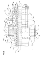
- the number 1 globally designates a ball screw actuator for aircraft control surfaces according to the present invention.
- the actuator 1 is housed within a structure 2 of the aircraft, for instance the tail boom, and commands the movement of a control surface 3, for example the stabiliser of the tail plane.
- the stabiliser 3 is moved by the actuator 1 about its own hinge axis 4, to change its own angle of attack.
- the actuator 1 comprises a lead screw 5 which is moved in rotation about its own longitudinal axis 6 by motor means 7, known and therefore illustrated only schematically in Figure 1, connected to the to the pilot's controls.
- a primary body 8 which in the specific technical field goes under the name of lead nut, coupled to the thread 9 of the screw 5 by means of a plurality of balls 10.
- the primary body 8 tubular shaped, has an inner surface 11 provided with seats 12 for the balls 10.
- the balls 10 are located in the throat 13 of the thread 9 and constitute the structural connection between the screw 5 and the nut 8.
- the balls 10 also keep at a certain distance the planar crest 14 of the thread 9 from the inner surface of the primary organ 8.
- the screw 5 is mounted by means of a primary support body 15 on the structure 2 of the aircraft and the primary body 8, connected to the control surface 3, slides along the longitudinal axis 6 of the screw 5.
- the support body 15 is pivotally engaged to the structure 2 in correspondence with a hinge 16.
- the primary body 8 is fastened to the support body 15 whilst the screw 5 slides axially inside the lead nut.
- the control surface 3 is connected to an end of the screw 5, for instance by means of an eyelet pivotally mounted on said end.
- the primary body 8 is connected to the control surface 3 by means of redundant structural elements. With reference to the preferred embodiment shown in Figure 2, the primary body 8 has two latching portions 17 which extend from opposite sides relative to the longitudinal axis 6 of the screw 5. Each of the latching portions 17 is engaged to the elevator 3.
- the primary body 8 is hinged to the control surface 3, in correspondence of its own latching portions 17, about a respective hinge axis 18.
- the rotation of the screw 5 in a direction or in the opposite one causes the sliding of the primary body 8 away (arrow A1) from the support 15 or towards (arrow B1) the support body 15.
- the primary body 8, moving away from the support body 15, causes the clockwise rotation of the stabiliser 3 (arrow A2).
- the primary body 8, moving towards the support body 15, causes the counter-clockwise rotation of the stabiliser 3 (arrow B2).
- the actuator 1 also comprises a secondary body 19 connected to the primary body 8.
- the primary body 8 can be directly connected to the secondary body 19, as shown in Figure 2, or even form a single body with the secondary body 19 itself.
- the secondary body 19 is connected directly to the control surface 3 and the primary body 8 is fastened to the secondary body 19 by means of the same control surface 3.
- the secondary body 19 is connected by means of a hinge 20 to the control surface 3.
- the hinge 20 is purposely constructed with a determined play so that, during the normal operation of the actuator 1, the lead screw 5 and the primary body 8 are allowed to rotate about their own hinge axis 18.
- the secondary body 19 has an auxiliary portion 21, preferably with tubular shape coaxial to the lead screw 5, provided with an engagement surface 22 facing the thread 9 of the screw 5 and at a predetermined distance from the thread 9.
- the engagement surface 22 is shaped to engage the thread 9. More in detail, the engagement surface 22, which coincides with the inner surface of the auxiliary portion 21 with tubular shape, has an inverse thread 23 shaped counter to the thread 9 of the screw 5 and adapted to engage on the thread 9 of the screw 5 itself ( Figures 2 and 3).
- the engagement surface 22 of the auxiliary portion 21 is made of material with high friction coefficient.
- the engagement surface 22 is made of frictionless material.
- the actuator 1 further comprises means 24 for uncoupling the secondary body 19 from the auxiliary portion 21 in the rotation motion about the longitudinal axis 6; said means are radially interposed between the secondary body 19 and the auxiliary portion 21.
- the uncoupling means 24 have at least a weakened portion 25 which connects the secondary body 19 to the auxiliary portion 21 and, preferably, friction reducing means 26 interposed between the auxiliary portion 21 and the secondary body 19.
- Both the weakened portion 25 and the friction reducing means 26 work on the rotation motion between the two aforementioned components.
- the removal of the weakened portion 25 allows the relative rotation between the secondary body 19 and the auxiliary portion 21 whilst the friction reducing means 26 facilitate said rotation.
- the two bodies 19, 21 are instead axially integral.
- the weakened connecting portion 25 is a pin inserted both in the secondary body 19 and in the auxiliary portion 21 whilst the friction reducing means 26 are defined by at least a bearing, for instance a ball bearing, which, radially interposed between the two bodies 19, 21, bears the loads in the direction of the longitudinal axis 6.
- the primary body 8 is preferably constituted by a tubular portion, which bears the inner surface 11 provided with the seats 12 for the balls 10.
- the secondary body 19 coaxially surrounds the auxiliary portion 21 and is connected, in the embodiment shown in Figure 2, to the primary body 8 about an axis 27 orthogonal to the longitudinal axis 6 of the control screw 5.
- the friction reducing means 26 have at least a bearing, preferably two bearings set side by side, interposed between the secondary body 19 and the auxiliary portion 21.
- the pin 25 is preferably inserted between the secondary body 19 and the auxiliary portion 21.
- the secondary body 19 has a first tubular body 28 radially distanced from the auxiliary portion 21 and a second tubular body 29 coaxial and integral to the first 28 and radially approached to the auxiliary portion 21 ( Figure 3).
- a containment chamber 30 in which are positioned the two bearings 26 inserted in annular recesses 31, 32 obtained respectively in the first tubular body 28 and in the auxiliary portion 21, to prevent the axial motion of one part relative to the other.
- a ring nut 33 fastened to the auxiliary portion 21 axially locks the bearings 26 and the auxiliary portion 21.
- the two bearings 26 are separated by spacers 34 and, between the secondary body 19 and the auxiliary portion 21, outside the bearings 26, are mounted two gaskets 35.
- the second tubular body 29 and the end of the auxiliary portion 21 approached thereto have respective coaxial holes 36, 37 for the insertion of the pin 25 which therefore is oriented transversely relative to the longitudinal axis 6 of the screw 5.
- the pin 25 exhibits a reduction of the section of its own stem 25a which, once placed in the holes 36, 37 is positioned in correspondence with the coupling surfaces between the second tubular body 29 and the end of the auxiliary portion 21.
- the secondary body 19 comprises two appendages 38 which extend towards the primary body 8 and engage the two latching portions 17.
- Each of the appendages 38 is formed by two arms 39 parallel to the longitudinal axis 6 of the screw 5 and provided with respective coaxial holes 40 into which is inserted one of the two latching portions 17.
- the articulation axis 27 thus coincides with the axis of the latching portion 17.
- the secondary body 19 is connected to the control surface in a manner that is wholly independent from the primary body 8.
- the primary body 8 moves on the screw 5 as specified above whilst the engagement surface 22 of the auxiliary portion 21 remains distanced from the thread 9 of the screw 5.
- the auxiliary portion 21 is not subject to any rotation, since the pin 25 makes it integral with the secondary body 19.
- the auxiliary portion 21 is uncoupled, in the rotation motion, from the secondary body 19 but remains integral with the same secondary body 19 along the longitudinal axis 6.
- the bearings 26 bear the loads along the longitudinal axis 6 of the screw 5 and the transverse loads caused by the loss of the coaxial condition between the screw 5 and the primary body 8 and secondary body 19.
- the screw 5 set in rotation by a command from the pilot, drags with it the auxiliary portion 21 which rotates freely. Consequently, the rotation of the screw 5 does not determine the axial motion of the secondary body 19, of the primary body 8, or the motion of the control surface 3. The pilot is unable to move the stabiliser.
- the aerodynamic forces acting on the control surface 3 are not able to move it.
- the moment generated by the aerodynamic about the hinge 4 of the control surface 3 unloads on the secondary body 19.
- the component along the longitudinal axis 6 of the force imparted on the secondary body 19 axially thrusts the auxiliary portion 21 but is unable to move it, since, along this direction, it is integral with the screw 5.
- the invention achieves important advantages.
- the actuator according to the present invention assures, following a failure, the immediate coupling of the safety device and the locking of the control surfaces.
- the seizure of the auxiliary portion on the screw and the separation, in the rotation motion, from the secondary body takes place at known loads, substantially determined by the strength of the connecting pin.
- the actuator according to the present invention allows to avoid further damage to the actuator and to recover nearly all of the parts that compose it during repair operations.
- the actuator according to the present invention is structurally simple and reliable.
Landscapes
- Engineering & Computer Science (AREA)
- General Engineering & Computer Science (AREA)
- Mechanical Engineering (AREA)
- Transmission Devices (AREA)
Applications Claiming Priority (2)
| Application Number | Priority Date | Filing Date | Title |
|---|---|---|---|
| IT000169A ITRM20030169A1 (it) | 2003-04-11 | 2003-04-11 | Attuatore a ricircolo di sfere per superfici di governo di aermobili. |
| ITRM20030169 | 2003-04-11 |
Publications (2)
| Publication Number | Publication Date |
|---|---|
| EP1467124A2 true EP1467124A2 (de) | 2004-10-13 |
| EP1467124A3 EP1467124A3 (de) | 2006-06-07 |
Family
ID=29765761
Family Applications (1)
| Application Number | Title | Priority Date | Filing Date |
|---|---|---|---|
| EP03425554A Withdrawn EP1467124A3 (de) | 2003-04-11 | 2003-08-20 | Kugelspindelantrieb für Flugzeugsteuerflächen |
Country Status (3)
| Country | Link |
|---|---|
| US (1) | US6851648B2 (de) |
| EP (1) | EP1467124A3 (de) |
| IT (1) | ITRM20030169A1 (de) |
Cited By (6)
| Publication number | Priority date | Publication date | Assignee | Title |
|---|---|---|---|---|
| FR2892786A1 (fr) * | 2005-11-02 | 2007-05-04 | Ratier Figeac Soc Par Actions | Ensemble vis-ecrou a protection anticorrosion. |
| EP1619414A3 (de) * | 2004-07-23 | 2007-12-05 | Jürgen Zimmermann | Stelleinrichtung |
| CN100513826C (zh) * | 2005-10-10 | 2009-07-15 | 西门子公司 | 用于诊断或治疗装置的主轴传动机构 |
| FR2970464A1 (fr) * | 2011-01-19 | 2012-07-20 | Goodrich Actuation Systems Sas | Perfectionnements aux actionneurs de commande de vol a ecrou secondaire |
| CN103495874A (zh) * | 2013-09-27 | 2014-01-08 | 苏州凯欧机械科技有限公司 | 一种防抱死精密工作台丝杠装置 |
| US9518672B2 (en) | 2010-06-21 | 2016-12-13 | Cameron International Corporation | Electronically actuated gate valve |
Families Citing this family (26)
| Publication number | Priority date | Publication date | Assignee | Title |
|---|---|---|---|---|
| DE102004047008A1 (de) * | 2004-09-28 | 2006-03-30 | Liebherr-Aerospace Lindenberg Gmbh | Vorrichtung zur Einstellung von Flugzeughöhenflossen |
| US7610828B2 (en) * | 2005-11-15 | 2009-11-03 | Honeywell International Inc. | Flight control surface actuator assembly including a free trial mechanism |
| US7322545B2 (en) * | 2005-12-29 | 2008-01-29 | The Boeing Company | Structural mechanism for unlocking and engaging a controllable surface on a hinged platform (wing) |
| US20080001037A1 (en) * | 2006-03-30 | 2008-01-03 | Roller Bearing Company Of America, Inc. | Actuator link assembly, flight control system and method of making same |
| US7641145B2 (en) * | 2006-11-21 | 2010-01-05 | Eaton Corporation | Apparatus for moving a control surface |
| FR2912374B1 (fr) * | 2007-02-08 | 2009-05-08 | Goodrich Actuation Systems Sas | Detection de la reprise d'effort par une voie secondaire d'un actionneur de commande de vol |
| FR2913949B1 (fr) * | 2007-03-23 | 2009-10-02 | Goodrich Actuation Systems Sas | Perfectionnements a la detection de la reprise d'effort de la voie secondaire d'un actionneur de commande de vol. |
| FR2916023B1 (fr) * | 2007-05-11 | 2009-08-21 | Goodrich Actuation Systems Sas | Liaison mecanique fusible entre deux ecrous sur un ensemble a vis de securite a defaillance. |
| ES2493640T3 (es) * | 2008-06-13 | 2014-09-12 | Moog Inc. | Método para determinar la integridad funcional aparente de un dispositivo antirretorno |
| WO2010005358A1 (en) * | 2008-07-11 | 2010-01-14 | Aktiebolaget Skf | A safety device for a linear actuator, and a linear actuator |
| FR2953494B1 (fr) * | 2009-12-08 | 2012-02-17 | Goodrich Actuation Systems Sas | Dispositif de test de la detection de la reprise effort par une voie secondaire d'un actionneur de commande de vol, et procede de test associe |
| US8590834B1 (en) * | 2011-11-14 | 2013-11-26 | The Boeing Company | Aircraft control surface actuation system with helical actuation path |
| DE102011086674A1 (de) * | 2011-11-18 | 2013-05-23 | Rolls-Royce Deutschland Ltd & Co Kg | Lagervorrichtung und Turbomaschine mit Lagervorrichtung |
| FR3016607B1 (fr) * | 2014-01-20 | 2016-01-22 | Sagem Defense Securite | Actionneur de commande d'un plan horizontal de stabilisation d'un aeronef |
| EP3072808B1 (de) * | 2015-03-26 | 2017-10-25 | Goodrich Actuation Systems SAS | Obere befestigung für einen trimmbaren horizontalen stabilisatoraktuator |
| EP3072809B1 (de) | 2015-03-27 | 2020-07-15 | Goodrich Actuation Systems SAS | Untere befestigung für einen trimmbaren horizontalen stabilisatoraktuator |
| CA2919342C (en) | 2015-04-15 | 2023-08-15 | Goodrich Actuation Systems Sas | Check device for flight actuator primary load path failure detection device |
| FR3044635B1 (fr) * | 2015-12-04 | 2018-08-17 | Ratier Figeac | Butee d'absorption d'energie de fin de course d'actionneur d'aeronef a portee destructible demontable, actionneur et aeronef |
| US11149828B2 (en) * | 2016-01-20 | 2021-10-19 | Eaton Intelligent Power Limited | Ball screw with secondary lead for failure detection |
| DE102016223978A1 (de) | 2016-12-01 | 2018-06-07 | Schaeffler Technologies AG & Co. KG | Spindeltrieb mit Arretierung |
| US10974846B2 (en) * | 2016-12-09 | 2021-04-13 | Parker-Hannifin Corporation | Fixed end electronic detection of secondary load path engagement of aircraft flight control actuator |
| US10933978B2 (en) * | 2017-01-10 | 2021-03-02 | Parker-Hannifin Corporation | Moving end electronic detection of secondary load path engagement of aircraft flight control actuator |
| US10801594B2 (en) * | 2018-05-30 | 2020-10-13 | The Boeing Company | Screw actuator, aircraft comprising a screw actuator, and method of lifting a load |
| US11255648B2 (en) * | 2018-11-08 | 2022-02-22 | Mbda Incorporated | Projectile with a range extending wing assembly |
| EP3789294B1 (de) * | 2019-09-04 | 2023-05-03 | Goodrich Actuation Systems SAS | Aktuator |
| CN112253713A (zh) * | 2020-11-19 | 2021-01-22 | 无锡艾尔特线性运动机械有限公司 | 具有安全螺母的滚珠丝杠组件 |
Citations (2)
| Publication number | Priority date | Publication date | Assignee | Title |
|---|---|---|---|---|
| US4644811A (en) | 1985-06-19 | 1987-02-24 | The United States Of America As Represented By The Secretary Of The Air Force | Termination load carrying device |
| US6467363B2 (en) | 2001-02-07 | 2002-10-22 | Moog Inc. | Ball screw actuator locking mechanism |
Family Cites Families (12)
| Publication number | Priority date | Publication date | Assignee | Title |
|---|---|---|---|---|
| US2447439A (en) * | 1945-12-12 | 1948-08-17 | Roy E Thompson | Self-locking screw |
| GB925995A (en) * | 1960-05-03 | 1963-05-15 | Ass Elect Ind | Improvements relating to screw lifting devices, but particularly for milling machines and like machine tools |
| CH437700A (fr) * | 1965-07-22 | 1967-06-15 | Villars Julio | Elévateur pour automobiles |
| US3467363A (en) * | 1967-08-31 | 1969-09-16 | Richard Alan Reichel | Noise generator for shaking loose packed material |
| US3630328A (en) * | 1970-08-24 | 1971-12-28 | Ltv Aerospace Corp | Linear actuator with braking device |
| DE3036940A1 (de) * | 1980-09-30 | 1982-05-13 | Siemens AG, 1000 Berlin und 8000 München | Schrauben-mutter-transmission zum vertikalen verschieben einer last |
| FR2663994B1 (fr) * | 1990-06-29 | 1994-06-10 | Ratier Figeac Soc | Verin rotatif a billes. |
| US5467661A (en) * | 1994-04-25 | 1995-11-21 | Thomson Saginaw Ball Screw Company, Inc. | Ball nut and screw assembly with backdrive control |
| JP3349098B2 (ja) * | 1998-09-18 | 2002-11-20 | 株式会社椿本チエイン | 落下防止機構付直線作動機 |
| GB0112984D0 (en) * | 2001-05-30 | 2001-07-18 | Lucas Industries Ltd | Screw actuator |
| EP1283384A3 (de) * | 2001-08-09 | 2004-08-11 | Smiths Wolverhampton Limited | Sicherungsmutter für eine Kugelumlaufspindel |
| US6672540B1 (en) * | 2002-12-03 | 2004-01-06 | Rockwell Collins, Inc. | Actuator for aircraft stabilizers with a failure responsive lock control mechanism |
-
2003
- 2003-04-11 IT IT000169A patent/ITRM20030169A1/it unknown
- 2003-08-19 US US10/642,603 patent/US6851648B2/en not_active Expired - Fee Related
- 2003-08-20 EP EP03425554A patent/EP1467124A3/de not_active Withdrawn
Patent Citations (2)
| Publication number | Priority date | Publication date | Assignee | Title |
|---|---|---|---|---|
| US4644811A (en) | 1985-06-19 | 1987-02-24 | The United States Of America As Represented By The Secretary Of The Air Force | Termination load carrying device |
| US6467363B2 (en) | 2001-02-07 | 2002-10-22 | Moog Inc. | Ball screw actuator locking mechanism |
Cited By (7)
| Publication number | Priority date | Publication date | Assignee | Title |
|---|---|---|---|---|
| EP1619414A3 (de) * | 2004-07-23 | 2007-12-05 | Jürgen Zimmermann | Stelleinrichtung |
| CN100513826C (zh) * | 2005-10-10 | 2009-07-15 | 西门子公司 | 用于诊断或治疗装置的主轴传动机构 |
| FR2892786A1 (fr) * | 2005-11-02 | 2007-05-04 | Ratier Figeac Soc Par Actions | Ensemble vis-ecrou a protection anticorrosion. |
| US9518672B2 (en) | 2010-06-21 | 2016-12-13 | Cameron International Corporation | Electronically actuated gate valve |
| FR2970464A1 (fr) * | 2011-01-19 | 2012-07-20 | Goodrich Actuation Systems Sas | Perfectionnements aux actionneurs de commande de vol a ecrou secondaire |
| WO2012098206A1 (fr) | 2011-01-19 | 2012-07-26 | Goodrich Actuation Systems Sas | Perfectionnements aux actionneurs de commande de vol a ecrou secondaire |
| CN103495874A (zh) * | 2013-09-27 | 2014-01-08 | 苏州凯欧机械科技有限公司 | 一种防抱死精密工作台丝杠装置 |
Also Published As
| Publication number | Publication date |
|---|---|
| ITRM20030169A0 (it) | 2003-04-11 |
| US6851648B2 (en) | 2005-02-08 |
| ITRM20030169A1 (it) | 2004-10-12 |
| US20040200929A1 (en) | 2004-10-14 |
| EP1467124A3 (de) | 2006-06-07 |
Similar Documents
| Publication | Publication Date | Title |
|---|---|---|
| US6851648B2 (en) | Ball screw actuator for aircraft control surfaces | |
| US8291782B1 (en) | Actuator assembly for stabilizers | |
| US20070108343A1 (en) | Flight control surface actuator assembly including a free trail mechanism | |
| US8496204B1 (en) | Method and system for minimizing axial backlash in a dual load path fail-safe aircraft actuator system | |
| US5743490A (en) | Flap/slat actuation system for an aircraft | |
| US8814085B2 (en) | Fault-tolerant actuating system for adjusting flaps of an aircraft, comprising adjustment kinematics with a fixed pivot, and a method for monitoring an actuating system | |
| US6928895B2 (en) | Ballscrew locking nut | |
| US8702035B2 (en) | Actuation apparatus for use on an aircraft | |
| EP3072808B1 (de) | Obere befestigung für einen trimmbaren horizontalen stabilisatoraktuator | |
| US20130313358A1 (en) | Tie Rod Lock | |
| EP3789294B1 (de) | Aktuator | |
| EP3751172B1 (de) | Aktuator mit gewindetrieb and verfahren zum herstellen denselben | |
| CN108216573A (zh) | 锁定装置 | |
| EP3127805B1 (de) | Untere befestigung für einen trimmbaren horizontalen stabilisatoraktuator | |
| EP4497676A1 (de) | Anordnung für ein flugzeug | |
| US9365286B2 (en) | Reversible decoupling device for actuators | |
| CA3063592A1 (en) | Actuator with declutchable output lever | |
| CN117469356A (zh) | 螺杆致动器 | |
| EP4206490B1 (de) | Ein horizontaler stabilisatorantrieb mit einem elektromechanischen linearantrieb | |
| EP1785347A2 (de) | Rekonfigurierbares Betätigungssystem für Flugzeugsteuerflächen und Verfahren | |
| US12434812B2 (en) | Aerodynamic system for an aircraft | |
| CN113365916B (zh) | 用于直升机的抗扭矩旋翼 | |
| US10591001B2 (en) | Fault tolerant actuator | |
| CN117799821A (zh) | 一种具有载荷限制功能的襟翼控制系统及飞机 | |
| GB2378494A (en) | Ballscrew locking nut |
Legal Events
| Date | Code | Title | Description |
|---|---|---|---|
| PUAI | Public reference made under article 153(3) epc to a published international application that has entered the european phase |
Free format text: ORIGINAL CODE: 0009012 |
|
| AK | Designated contracting states |
Kind code of ref document: A2 Designated state(s): AT BE BG CH CY CZ DE DK EE ES FI FR GB GR HU IE IT LI LU MC NL PT RO SE SI SK TR |
|
| AX | Request for extension of the european patent |
Extension state: AL LT LV MK |
|
| PUAL | Search report despatched |
Free format text: ORIGINAL CODE: 0009013 |
|
| AK | Designated contracting states |
Kind code of ref document: A3 Designated state(s): AT BE BG CH CY CZ DE DK EE ES FI FR GB GR HU IE IT LI LU MC NL PT RO SE SI SK TR |
|
| AX | Request for extension of the european patent |
Extension state: AL LT LV MK |
|
| RIC1 | Information provided on ipc code assigned before grant |
Ipc: F16H 25/22 20060101ALN20060420BHEP Ipc: B64C 13/28 20060101ALI20060420BHEP Ipc: F16H 25/24 20060101AFI20040721BHEP |
|
| 17P | Request for examination filed |
Effective date: 20061012 |
|
| 17Q | First examination report despatched |
Effective date: 20061222 |
|
| AKX | Designation fees paid |
Designated state(s): AT BE BG CH CY CZ DE DK EE ES FI FR GB GR HU IE IT LI LU MC NL PT RO SE SI SK TR |
|
| 17Q | First examination report despatched |
Effective date: 20061222 |
|
| STAA | Information on the status of an ep patent application or granted ep patent |
Free format text: STATUS: THE APPLICATION IS DEEMED TO BE WITHDRAWN |
|
| 18D | Application deemed to be withdrawn |
Effective date: 20070929 |