EP1467148A2 - Luftsystem für einen Wirbelbettkessel - Google Patents
Luftsystem für einen Wirbelbettkessel Download PDFInfo
- Publication number
- EP1467148A2 EP1467148A2 EP04100940A EP04100940A EP1467148A2 EP 1467148 A2 EP1467148 A2 EP 1467148A2 EP 04100940 A EP04100940 A EP 04100940A EP 04100940 A EP04100940 A EP 04100940A EP 1467148 A2 EP1467148 A2 EP 1467148A2
- Authority
- EP
- European Patent Office
- Prior art keywords
- air
- furnace
- fluidized
- supplied
- air supply
- Prior art date
- Legal status (The legal status is an assumption and is not a legal conclusion. Google has not performed a legal analysis and makes no representation as to the accuracy of the status listed.)
- Granted
Links
Images


Classifications
-
- F—MECHANICAL ENGINEERING; LIGHTING; HEATING; WEAPONS; BLASTING
- F23—COMBUSTION APPARATUS; COMBUSTION PROCESSES
- F23L—SUPPLYING AIR OR NON-COMBUSTIBLE LIQUIDS OR GASES TO COMBUSTION APPARATUS IN GENERAL ; VALVES OR DAMPERS SPECIALLY ADAPTED FOR CONTROLLING AIR SUPPLY OR DRAUGHT IN COMBUSTION APPARATUS; INDUCING DRAUGHT IN COMBUSTION APPARATUS; TOPS FOR CHIMNEYS OR VENTILATING SHAFTS; TERMINALS FOR FLUES
- F23L9/00—Passages or apertures for delivering secondary air for completing combustion of fuel
- F23L9/04—Passages or apertures for delivering secondary air for completing combustion of fuel by discharging the air beyond the fire, i.e. nearer the smoke outlet
-
- F—MECHANICAL ENGINEERING; LIGHTING; HEATING; WEAPONS; BLASTING
- F23—COMBUSTION APPARATUS; COMBUSTION PROCESSES
- F23C—METHODS OR APPARATUS FOR COMBUSTION USING FLUID FUEL OR SOLID FUEL SUSPENDED IN A CARRIER GAS OR AIR
- F23C10/00—Fluidised bed combustion apparatus
- F23C10/18—Details; Accessories
-
- F—MECHANICAL ENGINEERING; LIGHTING; HEATING; WEAPONS; BLASTING
- F23—COMBUSTION APPARATUS; COMBUSTION PROCESSES
- F23C—METHODS OR APPARATUS FOR COMBUSTION USING FLUID FUEL OR SOLID FUEL SUSPENDED IN A CARRIER GAS OR AIR
- F23C10/00—Fluidised bed combustion apparatus
- F23C10/18—Details; Accessories
- F23C10/28—Control devices specially adapted for fluidised bed, combustion apparatus
-
- F—MECHANICAL ENGINEERING; LIGHTING; HEATING; WEAPONS; BLASTING
- F23—COMBUSTION APPARATUS; COMBUSTION PROCESSES
- F23C—METHODS OR APPARATUS FOR COMBUSTION USING FLUID FUEL OR SOLID FUEL SUSPENDED IN A CARRIER GAS OR AIR
- F23C5/00—Disposition of burners with respect to the combustion chamber or to one another; Mounting of burners in combustion apparatus
- F23C5/08—Disposition of burners
- F23C5/28—Disposition of burners to obtain flames in opposing directions, e.g. impacting flames
Definitions
- the invention relates to a method for supplying upper air from upper air supply levels into a fluidized-bed boiler according to the preamble of the appended claim 1. Furthermore, the invention relates to an air system and a fluidized-bed boiler according to the preambles of the appended claims 4 and 7, respectively.
- Air is supplied to the lower part of the furnace of a fluidized-bed boiler via a grate into a fluidized bed formed by fluidized bed material on the grate, to fluidize the material of the fluidized bed.
- a fuel such as peat or bark
- a fuel channel onto the fluidized bed is supplied from a fuel channel onto the fluidized bed.
- About 40 to 70 % of the air needed for the combustion of the fuel is supplied as so-called primary air through the grate.
- upper air is typically supplied from two upper air levels into the furnace of the boiler.
- air jets of the secondary air level are provided above the fuel channel, and air jets of the tertiary air level are provided above these.
- the boiler typically comprises various burners which are used as start-up and auxiliary burners.
- upper air is typically introduced into the upper part of the furnace of the boiler on the secondary and tertiary air levels in such a way that 50 to 70 % of the upper air is supplied from the secondary air level, and the rest, i.e. 30 to 50 %, is supplied from the tertiary air level.
- Placing said secondary and tertiary air levels as far from each other as possible has an advantageous effect on the NO x contents of the flue gases from the boiler. For this reason, the aim is to place the tertiary air level as far up as possible.
- the air is typically introduced from both of the side walls of the furnace and, in some cases, from the front wall only.
- the primary aim of the present invention is to present an air system which produces an even temperature distribution in such a fluidized-bed boiler in which the rear wall cannot be provided with air jets.
- the method according to the invention is primarily characterized in what will be presented in the characterizing part of the independent claim 1.
- the air arrangement according to the invention is primarily characterized in what will be presented in the characterizing part of the independent claim 4.
- the fluidized-bed boiler according to the invention is primarily characterized in what will be presented in the characterizing part of the independent claim 7.
- the basic idea of the invention is to supply the fluidized-bed boiler with air from one or more upper air levels above the primary air level, from three directions.
- the primary air flows are provided from primary air nozzles placed in the wall opposite to the nose of the boiler, i.e. the front wall.
- Auxiliary air flows are provided from the side walls in such a way that the air flows supplied from auxiliary air nozzles in opposite walls are opposed to each other.
- the primary air flows and the auxiliary air flows are supplied substantially form the same level in such a way that said primary and auxiliary air flows are either on the same level or on slightly different levels.
- air can be evenly supplied onto the whole air supply level, to intensify the oxidation of the gases in the vicinity of the front wall. Furthermore, the air flow shifts the combustion process also to the area close to the rear wall underneath the nose, which improves the utilization of the volume of the boiler.
- the air system according to the invention reduces the turbulence of gases flowing inside the boiler when compared with a boiler in which the upper air is supplied from the front wall only, because in the system of the invention, it is possible to use lower strengths of the primary air jets.
- 40 to 80 % of the total quantity of air is supplied by the primary air jets from the front wall, and 20 to 60 % of the total quantity of air is supplied by the auxiliary air jets from the side walls.
- Another advantage of a preferred embodiment of the invention is a reduction in the corrosion and soiling of the superheaters, because the temperatures of the flue gases entering the superheater region are reduced.
- Figure 1 shows schematically a fluidized-bed boiler 1 with a furnace 2.
- a fluidized-bed boiler 1 From an air box 9 in the lower part of the fluidized-bed boiler 1, primary air is supplied through a grate to a fluidized bed 4 formed by fluidized bed material on the grate. In this way, the fluidized bed material is fluidized.
- Fuel is supplied from a fuel channel 5 onto the fluidized bed 4. Above the fuel channel 5, there is a secondary air level 10, whose single air jets are not shown in the figure. Above the secondary air level 10, there is a tertiary air level 11, whose single air jets are not shown in Fig. 1 either.
- the fluidized-bed boiler 1 typically comprises various burners which are used as start-up and auxiliary burners. Said burners are not illustrated in the figure.
- a nose 6 which is a structure protruding from the rear wall 13 towards the front wall 12 of the furnace.
- the nose 6 guides the flow of flue gases into superheaters 7 and further into the flue gas duct 8. Furthermore, the nose 6 is preferably used as a shield for the superheaters, separating the superheaters from a direct contact with the flame.
- the flue gas duct 8 is arranged to extend close to the rear wall 13 of the fluidized-bed boiler 1 and as far down as possible, the rear wall 13 of the boiler cannot be equipped with the structures of the upper air level 10, 11 at a height which would be advantageous for the combustion process.
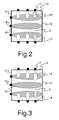
- the air systems of the upper air levels 10, 11 are preferably placed as shown in the invention, wherein the air jets 16, 17 and air channels are placed in three walls 12, 14, 15 of the furnace, and the rear wall 13 remains intact, as shown in Fig. 2.
- FIG. 2 shows the air system according to the invention, seen from above.
- This air system is suitable for use as secondary and tertiary air levels 10, 11 of the fluidized-bed boiler 1 of Fig. 1, but a similar air supply arrangement can also be used on other levels, such as, for example, a quaternary air level, by mai ntaining the basic idea of this invention.
- Figure 2 shows that the primary air flows 18 to be supplied from the primary air nozzles 16 placed in the front wall 12 are so strong that their flow preferably extends up to the rear wall 13.
- the primary air flows 18 carry a part of the combustible particles of the flue gases, or of the combustion gases, to the rear part of the furnace 2, which results in an efficient utilization of the volume of the furnace.
- the rate of the primary air flow 18 is advantageously 40 to 90 m/s and preferably 50 to 60 m/s in a fluidized-bed boiler 1 with a bottom whose one side has a length of about 10 metres and comprises 3 to 5 primary jets.
- auxiliary air flows 19, i.e. side air flows, are directed, which are significantly smaller than the primary air flows 18 in their strength.
- the auxiliary air flows 19 are directed from the opposite side walls 14, 15 in such a way that the auxi liary air flows are opposite to each other.
- the auxiliary air flow 19 supplied from the side wall 14, 15 is equal in strength with the auxiliary air flow supplied in the opposite direction from the opposite wall.
- the auxiliary air jets 17 on the opposite side walls 14, 15 are mirror images to each other.
- the auxiliary air flows 19 are supplied in such a way that their strength varies from the front wall 12 to the rear wall 13 of the fluidized-bed boiler 1.
- Figure 4 shows the temperature distribution in the fluidized-bed boiler 1 of Fig. 1 when the tertiary air supply level 11 of the boiler is implemented according to the invention.
- Figure 5 shows the temperature distribution for a boiler with a conventional arrangement, in which, on the tertiary air supply level, air is only supplied from air jets in the side walls.
Landscapes
- Engineering & Computer Science (AREA)
- Chemical & Material Sciences (AREA)
- Combustion & Propulsion (AREA)
- Mechanical Engineering (AREA)
- General Engineering & Computer Science (AREA)
- Fluidized-Bed Combustion And Resonant Combustion (AREA)
Applications Claiming Priority (2)
| Application Number | Priority Date | Filing Date | Title |
|---|---|---|---|
| FI20030542A FI114114B (fi) | 2003-04-10 | 2003-04-10 | Kerrosleijukattilan ilmajärjestelmä |
| FI20030542 | 2003-04-10 |
Publications (3)
| Publication Number | Publication Date |
|---|---|
| EP1467148A2 true EP1467148A2 (de) | 2004-10-13 |
| EP1467148A3 EP1467148A3 (de) | 2005-01-05 |
| EP1467148B1 EP1467148B1 (de) | 2007-07-18 |
Family
ID=8565948
Family Applications (1)
| Application Number | Title | Priority Date | Filing Date |
|---|---|---|---|
| EP04100940A Expired - Lifetime EP1467148B1 (de) | 2003-04-10 | 2004-03-09 | Luftsystem für einen Wirbelbettkessel |
Country Status (5)
| Country | Link |
|---|---|
| EP (1) | EP1467148B1 (de) |
| AT (1) | ATE367557T1 (de) |
| DE (1) | DE602004007569T2 (de) |
| ES (1) | ES2288240T3 (de) |
| FI (1) | FI114114B (de) |
Cited By (6)
| Publication number | Priority date | Publication date | Assignee | Title |
|---|---|---|---|---|
| CN102679331A (zh) * | 2012-03-28 | 2012-09-19 | 太原理工大学 | 一种循环流化床锅炉一次风机的控制方法 |
| CN106122953A (zh) * | 2016-08-29 | 2016-11-16 | 江苏汇能锅炉有限公司 | 一种循环流化床锅炉的一次风布风装置 |
| CN106555771A (zh) * | 2015-09-25 | 2017-04-05 | 上海上电漕泾发电有限公司 | 用于静叶可调引风机的静叶与变频联合控制方法 |
| US10982843B2 (en) | 2016-07-01 | 2021-04-20 | Teknologian Tutkimuskeskus Vtt Oy | Over fire arrangement and method |
| CN112902149A (zh) * | 2021-02-07 | 2021-06-04 | 哈尔滨工业大学 | 锅炉两侧墙上设有预燃室燃烧器的燃烧系统及燃烧方法 |
| CN113007698A (zh) * | 2021-02-07 | 2021-06-22 | 哈尔滨工业大学 | 一种用于对冲燃烧锅炉下层的燃烧系统及使用方法 |
Family Cites Families (6)
| Publication number | Priority date | Publication date | Assignee | Title |
|---|---|---|---|---|
| FI87246C (fi) * | 1989-04-10 | 1992-12-10 | Ahlstroem Oy | Foerfarande och anordning foer inmatning av foerbraenningsluft i en eldstad |
| FI89519C (fi) * | 1992-02-19 | 1997-08-19 | Ahlstrom Machinery Oy | Foerfarande och anordning foer oekande av saekerheten i en aotervinningspanna foer avlut |
| FI98936B (fi) * | 1992-10-19 | 1997-05-30 | Ahlstrom Machinery Oy | Menetelmä ja laite lämmön talteenottamiseksi jäteliemen talteenottokattilassa |
| SE503453C2 (sv) * | 1994-06-20 | 1996-06-17 | Kvaerner Pulping Tech | Sodapanna med ett sekundärlufttillflöde som åstadkommer en rotation av förbränningsgaserna och en förträngning av pannan ovanför lutinsprutningen samt ett förfarande vid en sådan panna |
| FI96436C (fi) * | 1994-08-10 | 1996-06-25 | Ahlstroem Oy | Menetelmä ja laite jätelipeän käsittelemiseksi |
| FI102411B (fi) * | 1997-02-07 | 1998-11-30 | Kvaerner Power Oy | Menetelmä ja sovitelma ilman syöttämiseksi leijukattilaan |
-
2003
- 2003-04-10 FI FI20030542A patent/FI114114B/fi not_active IP Right Cessation
-
2004
- 2004-03-09 ES ES04100940T patent/ES2288240T3/es not_active Expired - Lifetime
- 2004-03-09 DE DE602004007569T patent/DE602004007569T2/de not_active Expired - Lifetime
- 2004-03-09 AT AT04100940T patent/ATE367557T1/de active
- 2004-03-09 EP EP04100940A patent/EP1467148B1/de not_active Expired - Lifetime
Cited By (8)
| Publication number | Priority date | Publication date | Assignee | Title |
|---|---|---|---|---|
| CN102679331A (zh) * | 2012-03-28 | 2012-09-19 | 太原理工大学 | 一种循环流化床锅炉一次风机的控制方法 |
| CN106555771A (zh) * | 2015-09-25 | 2017-04-05 | 上海上电漕泾发电有限公司 | 用于静叶可调引风机的静叶与变频联合控制方法 |
| CN106555771B (zh) * | 2015-09-25 | 2019-04-05 | 上海上电漕泾发电有限公司 | 用于静叶可调引风机的静叶与变频联合控制方法 |
| US10982843B2 (en) | 2016-07-01 | 2021-04-20 | Teknologian Tutkimuskeskus Vtt Oy | Over fire arrangement and method |
| CN106122953A (zh) * | 2016-08-29 | 2016-11-16 | 江苏汇能锅炉有限公司 | 一种循环流化床锅炉的一次风布风装置 |
| CN112902149A (zh) * | 2021-02-07 | 2021-06-04 | 哈尔滨工业大学 | 锅炉两侧墙上设有预燃室燃烧器的燃烧系统及燃烧方法 |
| CN113007698A (zh) * | 2021-02-07 | 2021-06-22 | 哈尔滨工业大学 | 一种用于对冲燃烧锅炉下层的燃烧系统及使用方法 |
| CN112902149B (zh) * | 2021-02-07 | 2022-02-22 | 哈尔滨工业大学 | 锅炉两侧墙上设有预燃室燃烧器的燃烧方法 |
Also Published As
| Publication number | Publication date |
|---|---|
| ES2288240T3 (es) | 2008-01-01 |
| ATE367557T1 (de) | 2007-08-15 |
| EP1467148A3 (de) | 2005-01-05 |
| DE602004007569T2 (de) | 2008-04-10 |
| DE602004007569D1 (de) | 2007-08-30 |
| EP1467148B1 (de) | 2007-07-18 |
| FI114114B (fi) | 2004-08-13 |
| FI20030542A0 (fi) | 2003-04-10 |
Similar Documents
| Publication | Publication Date | Title |
|---|---|---|
| EP1148294B1 (de) | Wirbelschichtreaktor | |
| EP0981017B1 (de) | Kessel | |
| EP0761871B1 (de) | Kessel und Ofen zur Rückgewinnung im Kraftverfahren | |
| JP4859798B2 (ja) | ボイラ装置及びボイラ装置の改造方法 | |
| CA2272888C (en) | Circulating fluidized bed furnace/reactor with an integral secondary air plenum | |
| CA1176507A (en) | Fluidised beds | |
| AU2010224371B2 (en) | Circulating fluidized bed (CFB) with in-furnace secondary air nozzles | |
| EP1607680B1 (de) | Brennkammer mit Oberluftinjektion | |
| EP2467640B1 (de) | Verfahren und anordnung zur optimierung der verbrennungsbedingungen in einem wirbelschichtkessel | |
| EP1467148A2 (de) | Luftsystem für einen Wirbelbettkessel | |
| US5678497A (en) | Apparatus for distributing secondary air into a large scale circulating fluidized bed | |
| US5178531A (en) | Fluidized bed combustion furnace | |
| US5454908A (en) | Recovery boiler and method of reducing NOx emissions | |
| EP1386111B1 (de) | Verbrennungsluftsystem für rückgewinnungskessel, verbrennung verbrauchter laugen aus kochprozess | |
| US7694637B2 (en) | Method and apparatus for a simplified primary air system for improving fluid flow and gas mixing in recovery boilers | |
| CN206222303U (zh) | 一种燃煤锅炉超低nox燃烧系统 | |
| EP3054214B1 (de) | Verfahren zur zufuhr von luft zu einem wirbelbettkessel, wirbelbettkessel und brennstoffzufuhrmedien für einen wirbelbettkessel | |
| EP0722067A2 (de) | Wärmerückgewinnungseinrichtung für Wirbelbett | |
| FI128149B (en) | Method of introducing primary fluidizing gas into a furnace of a fluidized bed boiler | |
| US10982843B2 (en) | Over fire arrangement and method | |
| JPH039363B2 (de) | ||
| JPH09296384A (ja) | 回収ボイラ |
Legal Events
| Date | Code | Title | Description |
|---|---|---|---|
| PUAI | Public reference made under article 153(3) epc to a published international application that has entered the european phase |
Free format text: ORIGINAL CODE: 0009012 |
|
| AK | Designated contracting states |
Kind code of ref document: A2 Designated state(s): AT BE BG CH CY CZ DE DK EE ES FI FR GB GR HU IE IT LI LU MC NL PL PT RO SE SI SK TR |
|
| AX | Request for extension of the european patent |
Extension state: AL LT LV MK |
|
| PUAL | Search report despatched |
Free format text: ORIGINAL CODE: 0009013 |
|
| AK | Designated contracting states |
Kind code of ref document: A3 Designated state(s): AT BE BG CH CY CZ DE DK EE ES FI FR GB GR HU IE IT LI LU MC NL PL PT RO SE SI SK TR |
|
| AX | Request for extension of the european patent |
Extension state: AL LT LV MK |
|
| 17P | Request for examination filed |
Effective date: 20050617 |
|
| AKX | Designation fees paid |
Designated state(s): AT BE BG CH CY CZ DE DK EE ES FI FR GB GR HU IE IT LI LU MC NL PL PT RO SE SI SK TR |
|
| GRAP | Despatch of communication of intention to grant a patent |
Free format text: ORIGINAL CODE: EPIDOSNIGR1 |
|
| GRAS | Grant fee paid |
Free format text: ORIGINAL CODE: EPIDOSNIGR3 |
|
| GRAA | (expected) grant |
Free format text: ORIGINAL CODE: 0009210 |
|
| RAP1 | Party data changed (applicant data changed or rights of an application transferred) |
Owner name: METSO POWER OY |
|
| AK | Designated contracting states |
Kind code of ref document: B1 Designated state(s): AT BE BG CH CY CZ DE DK EE ES FI FR GB GR HU IE IT LI LU MC NL PL PT RO SE SI SK TR |
|
| REG | Reference to a national code |
Ref country code: GB Ref legal event code: FG4D |
|
| REG | Reference to a national code |
Ref country code: CH Ref legal event code: EP |
|
| REF | Corresponds to: |
Ref document number: 602004007569 Country of ref document: DE Date of ref document: 20070830 Kind code of ref document: P |
|
| REG | Reference to a national code |
Ref country code: IE Ref legal event code: FG4D |
|
| REG | Reference to a national code |
Ref country code: SE Ref legal event code: TRGR |
|
| ET | Fr: translation filed | ||
| REG | Reference to a national code |
Ref country code: ES Ref legal event code: FG2A Ref document number: 2288240 Country of ref document: ES Kind code of ref document: T3 |
|
| PG25 | Lapsed in a contracting state [announced via postgrant information from national office to epo] |
Ref country code: NL Free format text: LAPSE BECAUSE OF FAILURE TO SUBMIT A TRANSLATION OF THE DESCRIPTION OR TO PAY THE FEE WITHIN THE PRESCRIBED TIME-LIMIT Effective date: 20070718 Ref country code: FI Free format text: LAPSE BECAUSE OF FAILURE TO SUBMIT A TRANSLATION OF THE DESCRIPTION OR TO PAY THE FEE WITHIN THE PRESCRIBED TIME-LIMIT Effective date: 20070718 Ref country code: BG Free format text: LAPSE BECAUSE OF FAILURE TO SUBMIT A TRANSLATION OF THE DESCRIPTION OR TO PAY THE FEE WITHIN THE PRESCRIBED TIME-LIMIT Effective date: 20071018 Ref country code: PT Free format text: LAPSE BECAUSE OF FAILURE TO SUBMIT A TRANSLATION OF THE DESCRIPTION OR TO PAY THE FEE WITHIN THE PRESCRIBED TIME-LIMIT Effective date: 20071218 |
|
| REG | Reference to a national code |
Ref country code: CH Ref legal event code: PL |
|
| NLV1 | Nl: lapsed or annulled due to failure to fulfill the requirements of art. 29p and 29m of the patents act | ||
| PG25 | Lapsed in a contracting state [announced via postgrant information from national office to epo] |
Ref country code: CH Free format text: LAPSE BECAUSE OF FAILURE TO SUBMIT A TRANSLATION OF THE DESCRIPTION OR TO PAY THE FEE WITHIN THE PRESCRIBED TIME-LIMIT Effective date: 20070718 Ref country code: LI Free format text: LAPSE BECAUSE OF FAILURE TO SUBMIT A TRANSLATION OF THE DESCRIPTION OR TO PAY THE FEE WITHIN THE PRESCRIBED TIME-LIMIT Effective date: 20070718 Ref country code: PL Free format text: LAPSE BECAUSE OF FAILURE TO SUBMIT A TRANSLATION OF THE DESCRIPTION OR TO PAY THE FEE WITHIN THE PRESCRIBED TIME-LIMIT Effective date: 20070718 |
|
| PG25 | Lapsed in a contracting state [announced via postgrant information from national office to epo] |
Ref country code: BE Free format text: LAPSE BECAUSE OF FAILURE TO SUBMIT A TRANSLATION OF THE DESCRIPTION OR TO PAY THE FEE WITHIN THE PRESCRIBED TIME-LIMIT Effective date: 20070718 |
|
| PG25 | Lapsed in a contracting state [announced via postgrant information from national office to epo] |
Ref country code: GR Free format text: LAPSE BECAUSE OF FAILURE TO SUBMIT A TRANSLATION OF THE DESCRIPTION OR TO PAY THE FEE WITHIN THE PRESCRIBED TIME-LIMIT Effective date: 20071019 Ref country code: DK Free format text: LAPSE BECAUSE OF FAILURE TO SUBMIT A TRANSLATION OF THE DESCRIPTION OR TO PAY THE FEE WITHIN THE PRESCRIBED TIME-LIMIT Effective date: 20070718 |
|
| PLBE | No opposition filed within time limit |
Free format text: ORIGINAL CODE: 0009261 |
|
| STAA | Information on the status of an ep patent application or granted ep patent |
Free format text: STATUS: NO OPPOSITION FILED WITHIN TIME LIMIT |
|
| PG25 | Lapsed in a contracting state [announced via postgrant information from national office to epo] |
Ref country code: SK Free format text: LAPSE BECAUSE OF FAILURE TO SUBMIT A TRANSLATION OF THE DESCRIPTION OR TO PAY THE FEE WITHIN THE PRESCRIBED TIME-LIMIT Effective date: 20070718 Ref country code: CZ Free format text: LAPSE BECAUSE OF FAILURE TO SUBMIT A TRANSLATION OF THE DESCRIPTION OR TO PAY THE FEE WITHIN THE PRESCRIBED TIME-LIMIT Effective date: 20070718 |
|
| 26N | No opposition filed |
Effective date: 20080421 |
|
| PG25 | Lapsed in a contracting state [announced via postgrant information from national office to epo] |
Ref country code: RO Free format text: LAPSE BECAUSE OF FAILURE TO SUBMIT A TRANSLATION OF THE DESCRIPTION OR TO PAY THE FEE WITHIN THE PRESCRIBED TIME-LIMIT Effective date: 20070718 |
|
| PG25 | Lapsed in a contracting state [announced via postgrant information from national office to epo] |
Ref country code: MC Free format text: LAPSE BECAUSE OF NON-PAYMENT OF DUE FEES Effective date: 20080331 |
|
| PG25 | Lapsed in a contracting state [announced via postgrant information from national office to epo] |
Ref country code: IE Free format text: LAPSE BECAUSE OF NON-PAYMENT OF DUE FEES Effective date: 20080310 Ref country code: EE Free format text: LAPSE BECAUSE OF FAILURE TO SUBMIT A TRANSLATION OF THE DESCRIPTION OR TO PAY THE FEE WITHIN THE PRESCRIBED TIME-LIMIT Effective date: 20070718 |
|
| PG25 | Lapsed in a contracting state [announced via postgrant information from national office to epo] |
Ref country code: SI Free format text: LAPSE BECAUSE OF FAILURE TO SUBMIT A TRANSLATION OF THE DESCRIPTION OR TO PAY THE FEE WITHIN THE PRESCRIBED TIME-LIMIT Effective date: 20070718 |
|
| PG25 | Lapsed in a contracting state [announced via postgrant information from national office to epo] |
Ref country code: CY Free format text: LAPSE BECAUSE OF FAILURE TO SUBMIT A TRANSLATION OF THE DESCRIPTION OR TO PAY THE FEE WITHIN THE PRESCRIBED TIME-LIMIT Effective date: 20070718 |
|
| PG25 | Lapsed in a contracting state [announced via postgrant information from national office to epo] |
Ref country code: HU Free format text: LAPSE BECAUSE OF FAILURE TO SUBMIT A TRANSLATION OF THE DESCRIPTION OR TO PAY THE FEE WITHIN THE PRESCRIBED TIME-LIMIT Effective date: 20080119 Ref country code: LU Free format text: LAPSE BECAUSE OF NON-PAYMENT OF DUE FEES Effective date: 20080309 |
|
| PG25 | Lapsed in a contracting state [announced via postgrant information from national office to epo] |
Ref country code: TR Free format text: LAPSE BECAUSE OF FAILURE TO SUBMIT A TRANSLATION OF THE DESCRIPTION OR TO PAY THE FEE WITHIN THE PRESCRIBED TIME-LIMIT Effective date: 20070718 |
|
| PG25 | Lapsed in a contracting state [announced via postgrant information from national office to epo] |
Ref country code: IT Free format text: LAPSE BECAUSE OF NON-PAYMENT OF DUE FEES Effective date: 20080331 |
|
| REG | Reference to a national code |
Ref country code: FR Ref legal event code: PLFP Year of fee payment: 13 |
|
| PGFP | Annual fee paid to national office [announced via postgrant information from national office to epo] |
Ref country code: ES Payment date: 20160309 Year of fee payment: 13 |
|
| PGFP | Annual fee paid to national office [announced via postgrant information from national office to epo] |
Ref country code: GB Payment date: 20160321 Year of fee payment: 13 Ref country code: SE Payment date: 20160321 Year of fee payment: 13 Ref country code: AT Payment date: 20160322 Year of fee payment: 13 Ref country code: FR Payment date: 20160321 Year of fee payment: 13 |
|
| PGFP | Annual fee paid to national office [announced via postgrant information from national office to epo] |
Ref country code: DE Payment date: 20160330 Year of fee payment: 13 |
|
| REG | Reference to a national code |
Ref country code: DE Ref legal event code: R119 Ref document number: 602004007569 Country of ref document: DE |
|
| REG | Reference to a national code |
Ref country code: SE Ref legal event code: EUG |
|
| REG | Reference to a national code |
Ref country code: AT Ref legal event code: MM01 Ref document number: 367557 Country of ref document: AT Kind code of ref document: T Effective date: 20170309 |
|
| GBPC | Gb: european patent ceased through non-payment of renewal fee |
Effective date: 20170309 |
|
| PG25 | Lapsed in a contracting state [announced via postgrant information from national office to epo] |
Ref country code: SE Free format text: LAPSE BECAUSE OF NON-PAYMENT OF DUE FEES Effective date: 20170310 |
|
| REG | Reference to a national code |
Ref country code: FR Ref legal event code: ST Effective date: 20171130 |
|
| PG25 | Lapsed in a contracting state [announced via postgrant information from national office to epo] |
Ref country code: FR Free format text: LAPSE BECAUSE OF NON-PAYMENT OF DUE FEES Effective date: 20170331 Ref country code: DE Free format text: LAPSE BECAUSE OF NON-PAYMENT OF DUE FEES Effective date: 20171003 Ref country code: AT Free format text: LAPSE BECAUSE OF NON-PAYMENT OF DUE FEES Effective date: 20170309 |
|
| PG25 | Lapsed in a contracting state [announced via postgrant information from national office to epo] |
Ref country code: GB Free format text: LAPSE BECAUSE OF NON-PAYMENT OF DUE FEES Effective date: 20170309 |
|
| REG | Reference to a national code |
Ref country code: ES Ref legal event code: FD2A Effective date: 20180629 |
|
| PG25 | Lapsed in a contracting state [announced via postgrant information from national office to epo] |
Ref country code: ES Free format text: LAPSE BECAUSE OF NON-PAYMENT OF DUE FEES Effective date: 20170310 |