EP1467155A2 - Solaranlage - Google Patents
Solaranlage Download PDFInfo
- Publication number
- EP1467155A2 EP1467155A2 EP04450079A EP04450079A EP1467155A2 EP 1467155 A2 EP1467155 A2 EP 1467155A2 EP 04450079 A EP04450079 A EP 04450079A EP 04450079 A EP04450079 A EP 04450079A EP 1467155 A2 EP1467155 A2 EP 1467155A2
- Authority
- EP
- European Patent Office
- Prior art keywords
- primary
- heat exchanger
- circuit
- wat
- primary circuit
- Prior art date
- Legal status (The legal status is an assumption and is not a legal conclusion. Google has not performed a legal analysis and makes no representation as to the accuracy of the status listed.)
- Granted
Links
Images

Classifications
-
- F—MECHANICAL ENGINEERING; LIGHTING; HEATING; WEAPONS; BLASTING
- F24—HEATING; RANGES; VENTILATING
- F24D—DOMESTIC- OR SPACE-HEATING SYSTEMS, e.g. CENTRAL HEATING SYSTEMS; DOMESTIC HOT-WATER SUPPLY SYSTEMS; ELEMENTS OR COMPONENTS THEREFOR
- F24D19/00—Details
- F24D19/0095—Devices for preventing damage by freezing
-
- F—MECHANICAL ENGINEERING; LIGHTING; HEATING; WEAPONS; BLASTING
- F24—HEATING; RANGES; VENTILATING
- F24D—DOMESTIC- OR SPACE-HEATING SYSTEMS, e.g. CENTRAL HEATING SYSTEMS; DOMESTIC HOT-WATER SUPPLY SYSTEMS; ELEMENTS OR COMPONENTS THEREFOR
- F24D19/00—Details
- F24D19/10—Arrangement or mounting of control or safety devices
- F24D19/1006—Arrangement or mounting of control or safety devices for water heating systems
- F24D19/1009—Arrangement or mounting of control or safety devices for water heating systems for central heating
- F24D19/1042—Arrangement or mounting of control or safety devices for water heating systems for central heating the system uses solar energy
-
- F—MECHANICAL ENGINEERING; LIGHTING; HEATING; WEAPONS; BLASTING
- F24—HEATING; RANGES; VENTILATING
- F24S—SOLAR HEAT COLLECTORS; SOLAR HEAT SYSTEMS
- F24S40/00—Safety or protection arrangements of solar heat collectors; Preventing malfunction of solar heat collectors
- F24S40/70—Preventing freezing
-
- F—MECHANICAL ENGINEERING; LIGHTING; HEATING; WEAPONS; BLASTING
- F24—HEATING; RANGES; VENTILATING
- F24D—DOMESTIC- OR SPACE-HEATING SYSTEMS, e.g. CENTRAL HEATING SYSTEMS; DOMESTIC HOT-WATER SUPPLY SYSTEMS; ELEMENTS OR COMPONENTS THEREFOR
- F24D11/00—Central heating systems using heat accumulated in storage masses
-
- Y—GENERAL TAGGING OF NEW TECHNOLOGICAL DEVELOPMENTS; GENERAL TAGGING OF CROSS-SECTIONAL TECHNOLOGIES SPANNING OVER SEVERAL SECTIONS OF THE IPC; TECHNICAL SUBJECTS COVERED BY FORMER USPC CROSS-REFERENCE ART COLLECTIONS [XRACs] AND DIGESTS
- Y02—TECHNOLOGIES OR APPLICATIONS FOR MITIGATION OR ADAPTATION AGAINST CLIMATE CHANGE
- Y02B—CLIMATE CHANGE MITIGATION TECHNOLOGIES RELATED TO BUILDINGS, e.g. HOUSING, HOUSE APPLIANCES OR RELATED END-USER APPLICATIONS
- Y02B10/00—Integration of renewable energy sources in buildings
- Y02B10/20—Solar thermal
-
- Y—GENERAL TAGGING OF NEW TECHNOLOGICAL DEVELOPMENTS; GENERAL TAGGING OF CROSS-SECTIONAL TECHNOLOGIES SPANNING OVER SEVERAL SECTIONS OF THE IPC; TECHNICAL SUBJECTS COVERED BY FORMER USPC CROSS-REFERENCE ART COLLECTIONS [XRACs] AND DIGESTS
- Y02—TECHNOLOGIES OR APPLICATIONS FOR MITIGATION OR ADAPTATION AGAINST CLIMATE CHANGE
- Y02B—CLIMATE CHANGE MITIGATION TECHNOLOGIES RELATED TO BUILDINGS, e.g. HOUSING, HOUSE APPLIANCES OR RELATED END-USER APPLICATIONS
- Y02B10/00—Integration of renewable energy sources in buildings
- Y02B10/70—Hybrid systems, e.g. uninterruptible or back-up power supplies integrating renewable energies
-
- Y—GENERAL TAGGING OF NEW TECHNOLOGICAL DEVELOPMENTS; GENERAL TAGGING OF CROSS-SECTIONAL TECHNOLOGIES SPANNING OVER SEVERAL SECTIONS OF THE IPC; TECHNICAL SUBJECTS COVERED BY FORMER USPC CROSS-REFERENCE ART COLLECTIONS [XRACs] AND DIGESTS
- Y02—TECHNOLOGIES OR APPLICATIONS FOR MITIGATION OR ADAPTATION AGAINST CLIMATE CHANGE
- Y02E—REDUCTION OF GREENHOUSE GAS [GHG] EMISSIONS, RELATED TO ENERGY GENERATION, TRANSMISSION OR DISTRIBUTION
- Y02E10/00—Energy generation through renewable energy sources
- Y02E10/40—Solar thermal energy, e.g. solar towers
Definitions
- the invention relates to a solar system with a solar panel that has a Primary liquid circuit is connected to the primary side of a heat exchanger with a memory that is connected via a secondary liquid circuit to the secondary side of the Is connected to the heat exchanger, with a primary pump in the primary circuit and a secondary pump in the secondary circuit and with a controller for control of the pumps as a function of temperatures measured by means of sensors, where at least the primary circuit can be activated as soon as measured temperatures or their Differences exceed or fall below predefinable values.
- the completely closed primary circuit is one or more Solar panels, usually filled with water, which contains an antifreeze, z.
- the secondary circuit which is thermally via a heat exchanger, for. B. a plate exchanger, is connected to the primary circuit, but usually contains normal Tap water, which may also be available as process water, and to which no antifreeze can therefore be added.
- the liquid cools in the primary circuit, at least in the area of mostly weather unprotected solar collector to the respective outside temperature Temperatures, e.g. B. -15 ° C.
- the control is set up after a request for activation of the primary circuit with the help of a hydraulic medium for the time being the heat exchanger to maintain at least a substantially exclusive auxiliary primary cycle, until a temperature measured by a sensor in the area of the primary circuit Value excluding frost damage.
- the frost damage mentioned, in particular the heat exchanger be avoided in a simple and effective manner.
- a cheap and effective embodiment is characterized in that the hydraulic Means a valve arrangement in the primary circuit with which the primary side of the Heat exchanger can be bridged.
- valve arrangement is a three-way valve is used to bypass the primary side of the heat exchanger can be bridged.
- the three-way valve is in the return of the primary circuit is seated and connected to the bypass.
- Another improvement This is particularly the case when the outside temperature is very low, if in the inlet of the primary circuit a check valve is arranged on the side of the heat exchanger.
- valve arrangement consists of two three-way valves on both sides of the bypass, which is controlled by the controller at Bridging the primary side of the heat exchanger completely from the primary side disconnect the part of the primary circuit containing the collector.
- a version is also characterized by special security in which the Valve arrangement consists of a four-way valve, which is controlled by the controller, if the primary side of the heat exchanger is bypassed, this primary side completely separates the part of the primary circuit containing the solar collector.
- a primary auxiliary pump is provided, which according to Activation by the controller near the collector, a primary, the heat exchanger excluding auxiliary circuit can maintain until a minimum temperature in the Collector area is reached.
- auxiliary pump it can be useful be when in the primary circuit between the auxiliary pump and the heat exchanger Check valve is arranged.
- the schematically shown solar system has a solar collector SOK, which has a Primary liquid circuit PKL connected to the primary side of a WAT heat exchanger is.
- a primary pump PPU pumps a liquid, usually a water-methanol mixture in this closed primary circuit between the solar collector SOK and the primary side of the WAT heat exchanger.
- the latter can be used, for example, as a plate exchanger be trained.
- the SOK solar collector can of course consist of several exist in parallel and / or in series units.
- the secondary circuit SKL is on the one hand on the secondary side of the heat exchanger WAT and on the other hand connected to a water storage SPE, with a secondary pump SPU ensures the pumping of water in the secondary circuit SKL. If in operation or heat radiation falls on the solar collector SOK, which is in the primary circuit PKL circulating fluid warms constantly and gives your warmth over the Heat exchanger WAT from the secondary circuit SKL, with a heat storage in the memory SPE takes place, d. H. the water in this SPE tank heats up. Depending on Conception of the solar system can use the water from the SPE or in the secondary circuit SKL are used in a manner not shown here for heating purposes and / or as Process water in a household or business. The corresponding connection fittings etc. are not shown here because they are not essential to the invention.
- a STE control system is also provided here
- Dependency mainly on different temperatures measured by sensors the system switches on and generally controls various valves and pumps, which control the operation adapts the system to the existing or desired temperatures.
- the one created here Control is only explained to the extent that it is in connection with the invention stands. In fact, the controller can perform other tasks, especially related with the heat and water supply on the secondary side.
- the temperature T1 in the range of Solar collector SOK measured and the corresponding measured value supplied to the control STE The same applies to the temperature T2 measured in the storage area, for which a Temperature sensor S2 is provided.
- This sensor S2 can, for example, the temperature Measure the water in the SPE tank at a selected point.
- a temperature sensor S3 the temperature T3 in the primary circuit is removed from the Solar collector measured SOK.
- a sun sensor S4 can also be provided, which measures a temperature T4 or one of the irradiation power, measured e.g. B. in W / m 2 , measures the corresponding value.
- PKL In the return of the primary circuit PKL is a three-way valve in the manner shown inserted, which also has a bypass BYP with the inlet from the heat exchanger WAT is connected to the solar collector SOK. Besides, there is still between Bypass BYP and the heat exchanger WAT in the inlet a check valve RSV inserted.
- the three-way valve V1 controlled by the control STE can be controlled in such a way that it either completely releases the return line, causing the circulation caused by the PPU pump undisturbed between the SOK solar collector and the primary side of the WAT heat exchanger can go on.
- the valve can be controlled so that the primary side of the WAT heat exchanger is excluded from this cycle by the BYP bypass is.
- the controller is now set up to start the primary pump PPU when the temperature T1 on the collector-side sensor S1 is measured with the memory-side sensor S2 Temperature T2 exceeds an adjustable size. The start can be additional be made dependent on a predefinable minimum temperature T1 at sensor S1 was achieved. Now the water is pumped by the pump PPU in the primary circuit PKL.
- Another predefinable starting condition is that the one recorded with the sun sensor S4 Temperature or radiation value T4 exceeds a certain value and also the temperature T2 exceeds the temperature T1 by a certain amount.
- the starting condition can also be that the temperature or radiation value T4 exceeds a certain value and additionally the temperature T1 in the collector area has a minimum value.
- the invention now uses here that the liquid when the primary pump PPU is switched on does not flow over the primary side of the heat exchanger WAT, but through it accordingly switched valve V1 via the bypass BYP past the heat exchanger WAT back towards the SOK solar collector. Only then will the control switch valve V1 um if the primary pump PPU has been in operation for some time and until the one with the Sensor S3 measured temperature T3 has reached a value that prevents frost damage.
- the temperature T3 should no longer have minus degrees, for example.
- the above-mentioned time delay is necessary for PKL to be in the primary circuit halfway steady temperature condition is reached.
- the temperatures can be very different when the solar panel SOK is outdoors and is covered with ice or snow, for example, whereas in general the three-way valve V1 and the primary pump PPU in a more protected Area, e.g. B. are arranged in a building.
- the temperature T3 you can additionally or alternatively, also set the condition that the temperature T1 in the collector area has a certain minimum value
- Preventing PKL can occur between the WAT heat exchanger and the bypass BYP a check valve RSV can be used in the manner shown in FIG. 1.
- a further three-way valve V2 is provided, specifically on the other end of the BYP bypass in the forward of the primary circuit PKL.
- the three-way valve V1 from FIG. 1 is designated here by the reference symbol V1 '.
- Both three-way valves V1 'and V2 are controlled by the controller STE so that in the initial state After switching on the system, the primary pump PPU only over the liquid drives the bypass BYP past the primary side of the WAT heat exchanger.
- the check valve RSV of FIG. 1 can of course be omitted. For the rest is this design is completely identical to that of Fig. 1.
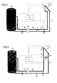
- Fig. 3 shows that in place of a three-way valve VI or two three-way valves V1 ', V2 Four-way valve V3 can be provided.
- This valve V3 is also controlled by the STE control system controlled so that in the initial operating state already described, in which the liquid in the primary circuit PKL is still so cold that damage to the Heat exchanger WAT is to be feared, the liquid directly via the four-way valve V3 is pumped using the primary pump PPU, past the primary side of the WAT heat exchanger.
- the STE control switches the four-way valve V3 so that the normal Operating state is reached in which the liquid in the primary circuit PKL from the solar collector SOK flows directly to and from the primary side of the WAT heat exchanger driven here by the pump PPU back to the solar collector SOK. in the the rest is also the same here as in FIGS. 1 and 2.
- FIG. 4 A variant that does not use controllable valves is shown in FIG. 4.
- one additional pump namely an auxiliary pump HPU at the solar collector SOK or in its proximity arranged in a bypass. If this auxiliary pump HPU is in operation, a new cycle of the SOK solar collector can be maintained.
- the temperature T3 is measured in this circuit, somewhat away from the SOK solar collector, whereas the temperature T1 in the immediate area of the solar collector SOK or at this is measured.
- the control STE is thus set up to operate the system according to the above or switch on other temperature-dependent starting conditions, e.g. B. the auxiliary pump Then switch on the HPU when the temperature T1 at the sensor S1 near the collector, the temperature T2 measured with the sensor S2 in the memory SPE by an adjustable Size exceeds and when a minimum temperature T1 has been reached at the sensor S1.
- the liquid in the primary circuit PKL then only becomes as described pumped in a small circuit near the SOK solar collector. To creep in this state To avoid circulation in the pipeline in the direction of the WAT heat exchanger, an appropriate distance must be observed, or such a creeping Circulation by installing, for example, a check valve RSV, as in FIG. 4 shown, can be prevented. Of course, it is also possible to install an additional shut-off valve.
- the control also has a differential control for the secondary circuit SKL, the Temperatures T3 and T2 are compared. As soon as the temperature T3 at the sensor S3 the temperature T2, which is measured in the memory SPE with the sensor S2 by a adjustable size exceeds and a predetermined minimum temperature T3 on the sensor S3 is reached, the secondary pump SPU and the actual primary pump PPU switched on and the auxiliary pump HPU in the bypass BPA is switched off.
Landscapes
- Engineering & Computer Science (AREA)
- General Engineering & Computer Science (AREA)
- Chemical & Material Sciences (AREA)
- Thermal Sciences (AREA)
- Combustion & Propulsion (AREA)
- Mechanical Engineering (AREA)
- Physics & Mathematics (AREA)
- Life Sciences & Earth Sciences (AREA)
- Sustainable Development (AREA)
- Sustainable Energy (AREA)
- Air Conditioning Control Device (AREA)
- Other Air-Conditioning Systems (AREA)
- Control Of Temperature (AREA)
Abstract
Description
Claims (9)
- Solaranlage mit einem Sonnenkollektor (SOK), der über einen Primär-Flüssigkeitskreislauf (PKL) an die Primärseite eines Wärmetauschers (WAT) angeschlossen ist, mit einem Speicher (SPE), der über einen Sekundär-Flüssigkeitskreislauf (SKL) an die Sekundärseite des Wärmetauschers angeschlossen ist, mit einer Primärpumpe (PPU) in dem Primärkreislauf und einer Sekundärpumpe (SPU) in dem Sekundärkreislauf sowie mit einer Steuerung (STE) zur Ansteuerung der Pumpen (PPU, SPU) in Abhängigkeit von mittels Sensoren (S1, S2, S3, S4) gemessenen Temperaturen (T1 bzw. T4), wobei zumindest der Primärkreislauf aktivierbar ist, sobald gemessene Temperaturen (T4) oder deren Differenzen vorgebbare Werte über- oder unterschreiten,
dadurch gekennzeichnet, dass
die Steuerung (STE) dazu eingerichtet ist, nach einer Aufforderung zum Aktivieren des Primärkreislaufs mit Hilfe eines hydraulischen Mittels (V1, V1' + V2, HPU, V3) vorerst einen den Wärmetauscher (WAT) zumindest im wesentlichen ausschließenden Hilfsprimärkreislauf aufrecht zu erhalten, bis eine mittels eines Sensors (S3, S1) im Bereich des Primärkreislaufs und/oder des Kollektors (SOK) gemessene Temperatur (T3, T1) einen Frostschäden ausschließenden Wert übersteigt. - Solaranlage nach Anspruch 1, dadurch gekennzeichnet, dass das hydraulische Mittel eine Ventilanordnung (V1, V1' + V2, V3) im Primärkreislauf ist, mit welcher die Primärseite des Wärmetauschers (WAT) überbrückbar ist.
- Solaranlage nach Anspruch 2, dadurch gekennzeichnet, dass die Ventilanordnung ein Dreiwegeventil (V1) ist, mit dessen Hilfe die Primärseite des Wärmetauschers über einen Bypass (BYP) überbrückbar ist.
- Solaranlage nach Anspruch 3, dadurch gekennzeichnet, dass das Dreiwegeventil (V1) im Rücklauf des Primärkreislaufs sitzt und mit dem Bypass (BYP) verbunden ist.
- Solaranlage nach einem der Ansprüche 2 bis 4, dadurch gekennzeichnet, dass im Zulauf des Primärkreislaufs an der Seite des Wärmetauschers (WAT) ein Rückschlagventil (RSV) angeordnet ist.
- Solaranlage nach Anspruch 2, dadurch gekennzeichnet, dass die Ventilanordnung aus zwei Dreiwegeventilen (V1', V2) an den beiden Seiten des Bypass (BYP) besteht, welche von der Steuerung (STE) gesteuert bei Überbrückung der Primärseite des Wärmetauschers (WAT) diese Primärseite vollständig von dem den Kollektor (SOK) enthaltenden Teil des Primärkreislaufs abtrennen.
- Solaranlage nach Anspruch 2, dadurch gekennzeichnet, dass die Ventilanordnung aus einem Vierwegeventil (V3) besteht, welches von der Steuerung (STE) gesteuert, bei Überbrückung der Primärseite des Wärmetauschers (WAT) diese Primärseite vollständig von dem den Sonnenkollektor (SOK) enthaltenden Teil des Primärkreislaufs (PKL) abtrennt.
- Solaranlage nach Anspruch 1, dadurch gekennzeichnet, dass zusätzlich zu der Primärkreispumpe (PPU) eine primäre Hilfspumpe (HPU) vorgesehen ist, welche nach Aktivierung durch die Steuerung (STE) kollektornahe einen primären, den Wärmetauscher (WAT) ausschließenden Hilfskreislauf aufrecht erhalten kann, bis eine Mindesttemperatur (T1) im Kollektorbereich erreicht ist.
- Solaranlage nach Anspruch 8, dadurch gekennzeichnet, dass im Primärkreislauf (PKL) zwischen Hilfspumpe (HPU) und Wärmetauscher (WAT) ein Rückschlagventil (RSV) angeordnet ist.
Applications Claiming Priority (2)
| Application Number | Priority Date | Filing Date | Title |
|---|---|---|---|
| AT5542003 | 2003-04-09 | ||
| AT0055403A AT412505B (de) | 2003-04-09 | 2003-04-09 | Solaranlage |
Publications (3)
| Publication Number | Publication Date |
|---|---|
| EP1467155A2 true EP1467155A2 (de) | 2004-10-13 |
| EP1467155A3 EP1467155A3 (de) | 2004-12-15 |
| EP1467155B1 EP1467155B1 (de) | 2009-09-30 |
Family
ID=32831418
Family Applications (1)
| Application Number | Title | Priority Date | Filing Date |
|---|---|---|---|
| EP04450079A Expired - Lifetime EP1467155B1 (de) | 2003-04-09 | 2004-04-01 | Solaranlage |
Country Status (3)
| Country | Link |
|---|---|
| EP (1) | EP1467155B1 (de) |
| AT (2) | AT412505B (de) |
| DE (1) | DE502004010143D1 (de) |
Cited By (4)
| Publication number | Priority date | Publication date | Assignee | Title |
|---|---|---|---|---|
| EP2009359A3 (de) * | 2007-06-29 | 2014-08-13 | Vaillant GmbH | Solarthermische Anlage und Verfahren zum Betrieb einer solchen Anlage |
| CN108266781A (zh) * | 2018-02-07 | 2018-07-10 | 北京民利储能技术有限公司 | 一种熔盐供暖装置 |
| CN111306609A (zh) * | 2020-02-27 | 2020-06-19 | 中国第一汽车股份有限公司 | 一种楼宇分时控制采暖温度节能系统 |
| CN112050282A (zh) * | 2020-09-09 | 2020-12-08 | 大连理工大学 | 智能感知热回收太阳能供暖屋顶系统 |
Family Cites Families (3)
| Publication number | Priority date | Publication date | Assignee | Title |
|---|---|---|---|---|
| DE2722451A1 (de) * | 1977-05-18 | 1978-11-30 | Bosch Gmbh Robert | Einrichtung zur waermeversorgung mit sonnenkollektoren |
| DE4006562A1 (de) * | 1990-03-02 | 1991-09-12 | Friedrich Mueller | Sonnenkollektoranlage und verfahren zum steuern einer solchen |
| EP0596006B1 (de) * | 1991-07-24 | 1996-09-18 | Rheem Australia Limited | Sonnenwärmekollektor mit schutz gegen frostschaden |
-
2003
- 2003-04-09 AT AT0055403A patent/AT412505B/de not_active IP Right Cessation
-
2004
- 2004-04-01 EP EP04450079A patent/EP1467155B1/de not_active Expired - Lifetime
- 2004-04-01 AT AT04450079T patent/ATE444470T1/de not_active IP Right Cessation
- 2004-04-01 DE DE502004010143T patent/DE502004010143D1/de not_active Expired - Fee Related
Cited By (5)
| Publication number | Priority date | Publication date | Assignee | Title |
|---|---|---|---|---|
| EP2009359A3 (de) * | 2007-06-29 | 2014-08-13 | Vaillant GmbH | Solarthermische Anlage und Verfahren zum Betrieb einer solchen Anlage |
| CN108266781A (zh) * | 2018-02-07 | 2018-07-10 | 北京民利储能技术有限公司 | 一种熔盐供暖装置 |
| CN111306609A (zh) * | 2020-02-27 | 2020-06-19 | 中国第一汽车股份有限公司 | 一种楼宇分时控制采暖温度节能系统 |
| CN112050282A (zh) * | 2020-09-09 | 2020-12-08 | 大连理工大学 | 智能感知热回收太阳能供暖屋顶系统 |
| CN112050282B (zh) * | 2020-09-09 | 2024-05-24 | 大连理工大学 | 智能感知热回收太阳能供暖屋顶系统 |
Also Published As
| Publication number | Publication date |
|---|---|
| ATA5542003A (de) | 2004-08-15 |
| AT412505B (de) | 2005-03-25 |
| EP1467155B1 (de) | 2009-09-30 |
| DE502004010143D1 (de) | 2009-11-12 |
| ATE444470T1 (de) | 2009-10-15 |
| EP1467155A3 (de) | 2004-12-15 |
Similar Documents
| Publication | Publication Date | Title |
|---|---|---|
| EP3447403A1 (de) | Betriebsverfahren für wärmegewinnungsanlagen, luft/flüssigkeit-wärmetauschereinheit und wärmegewinnungsanlage | |
| DE202009006988U1 (de) | Warmwasserversorgungsanlage mit einem Warmwasserspeicher | |
| DE102008057495A1 (de) | Wärmespeicheranordnung | |
| EP1467155B1 (de) | Solaranlage | |
| DE102010017148A1 (de) | Verfahren zum Betreiben einer Wärmegewinnungsanlage | |
| EP0444403B1 (de) | Verfahren zum Steuern einer Sonnenkollektoranlage | |
| DE20301965U1 (de) | Steuervorrichtung für eine Solaranlage | |
| DE602004000871T2 (de) | Kombinierte Solarheizungsanlage mit Überhitzungsverwaltung und Verfahren zur Regulierung der Anlage. | |
| DE102014000671B4 (de) | Solaranlage und Verfahren zum Betreiben einer solchen | |
| DE10341741B4 (de) | Solaranlage | |
| DE202009017577U1 (de) | Heiz- und Kühleinrichtungen mit einer Wärmepumpe | |
| EP2405205B1 (de) | Gasabscheider in einer Solaranlage zur Wärmegewinnung | |
| EP2827082B1 (de) | Verfahren zum Steuern eines Kompressors einer Wärmepumpe | |
| DE102008020637A1 (de) | Warmwasserversorgungsanlage mit einem Warmwasserspeicher | |
| EP2783164B1 (de) | Verfahren zum betrieb einer fluidleitungsvorrichtung | |
| DE3005848C2 (de) | ||
| AT509723B1 (de) | Frostschutzeinrichtung | |
| DE19804048A1 (de) | Solaranlage zur Wärmeerzeugung | |
| CH682011A5 (de) | ||
| DE102013017677A1 (de) | Verfahren und Anordnung zum Beheizen von Gebäuden mit einer lnfrarot-Heizung | |
| DE3043123C2 (de) | Heizungsanlage mit einer Wärmepumpe | |
| DE29516951U1 (de) | Wärmepumpenanlage | |
| EP4737807A1 (de) | Haustechnikgerät für ein gebäude, verfahren zum montieren eines haustechnikgeräts sowie verfahren zum betreiben eines haustechnikgeräts | |
| DE102022123938A1 (de) | Solaranlage und Verfahren zu deren Betreiben | |
| EP4671628A1 (de) | Anlage zur wärmeversorgung eines gebäudes und betriebvsverfahren |
Legal Events
| Date | Code | Title | Description |
|---|---|---|---|
| PUAI | Public reference made under article 153(3) epc to a published international application that has entered the european phase |
Free format text: ORIGINAL CODE: 0009012 |
|
| AK | Designated contracting states |
Kind code of ref document: A2 Designated state(s): AT BE BG CH CY CZ DE DK EE ES FI FR GB GR HU IE IT LI LU MC NL PL PT RO SE SI SK TR |
|
| AX | Request for extension of the european patent |
Extension state: AL HR LT LV MK |
|
| PUAL | Search report despatched |
Free format text: ORIGINAL CODE: 0009013 |
|
| AK | Designated contracting states |
Kind code of ref document: A3 Designated state(s): AT BE BG CH CY CZ DE DK EE ES FI FR GB GR HU IE IT LI LU MC NL PL PT RO SE SI SK TR |
|
| AX | Request for extension of the european patent |
Extension state: AL HR LT LV MK |
|
| RIC1 | Information provided on ipc code assigned before grant |
Ipc: 7F 24D 19/10 A Ipc: 7F 24J 2/46 B |
|
| 17P | Request for examination filed |
Effective date: 20050524 |
|
| AKX | Designation fees paid |
Designated state(s): AT BE BG CH CY CZ DE DK EE ES FI FR GB GR HU IE IT LI LU MC NL PL PT RO SE SI SK TR |
|
| GRAP | Despatch of communication of intention to grant a patent |
Free format text: ORIGINAL CODE: EPIDOSNIGR1 |
|
| GRAS | Grant fee paid |
Free format text: ORIGINAL CODE: EPIDOSNIGR3 |
|
| GRAA | (expected) grant |
Free format text: ORIGINAL CODE: 0009210 |
|
| AK | Designated contracting states |
Kind code of ref document: B1 Designated state(s): AT BE BG CH CY CZ DE DK EE ES FI FR GB GR HU IE IT LI LU MC NL PL PT RO SE SI SK TR |
|
| REG | Reference to a national code |
Ref country code: GB Ref legal event code: FG4D Free format text: NOT ENGLISH Ref country code: CH Ref legal event code: EP |
|
| REG | Reference to a national code |
Ref country code: CH Ref legal event code: NV Representative=s name: SIEMENS SCHWEIZ AG |
|
| REG | Reference to a national code |
Ref country code: IE Ref legal event code: FG4D |
|
| REF | Corresponds to: |
Ref document number: 502004010143 Country of ref document: DE Date of ref document: 20091112 Kind code of ref document: P |
|
| PG25 | Lapsed in a contracting state [announced via postgrant information from national office to epo] |
Ref country code: SE Free format text: LAPSE BECAUSE OF FAILURE TO SUBMIT A TRANSLATION OF THE DESCRIPTION OR TO PAY THE FEE WITHIN THE PRESCRIBED TIME-LIMIT Effective date: 20090930 Ref country code: FI Free format text: LAPSE BECAUSE OF FAILURE TO SUBMIT A TRANSLATION OF THE DESCRIPTION OR TO PAY THE FEE WITHIN THE PRESCRIBED TIME-LIMIT Effective date: 20090930 |
|
| PG25 | Lapsed in a contracting state [announced via postgrant information from national office to epo] |
Ref country code: PL Free format text: LAPSE BECAUSE OF FAILURE TO SUBMIT A TRANSLATION OF THE DESCRIPTION OR TO PAY THE FEE WITHIN THE PRESCRIBED TIME-LIMIT Effective date: 20090930 Ref country code: SI Free format text: LAPSE BECAUSE OF FAILURE TO SUBMIT A TRANSLATION OF THE DESCRIPTION OR TO PAY THE FEE WITHIN THE PRESCRIBED TIME-LIMIT Effective date: 20090930 |
|
| NLV1 | Nl: lapsed or annulled due to failure to fulfill the requirements of art. 29p and 29m of the patents act | ||
| PG25 | Lapsed in a contracting state [announced via postgrant information from national office to epo] |
Ref country code: RO Free format text: LAPSE BECAUSE OF FAILURE TO SUBMIT A TRANSLATION OF THE DESCRIPTION OR TO PAY THE FEE WITHIN THE PRESCRIBED TIME-LIMIT Effective date: 20090930 Ref country code: PT Free format text: LAPSE BECAUSE OF FAILURE TO SUBMIT A TRANSLATION OF THE DESCRIPTION OR TO PAY THE FEE WITHIN THE PRESCRIBED TIME-LIMIT Effective date: 20100201 Ref country code: ES Free format text: LAPSE BECAUSE OF FAILURE TO SUBMIT A TRANSLATION OF THE DESCRIPTION OR TO PAY THE FEE WITHIN THE PRESCRIBED TIME-LIMIT Effective date: 20100110 Ref country code: EE Free format text: LAPSE BECAUSE OF FAILURE TO SUBMIT A TRANSLATION OF THE DESCRIPTION OR TO PAY THE FEE WITHIN THE PRESCRIBED TIME-LIMIT Effective date: 20090930 Ref country code: CZ Free format text: LAPSE BECAUSE OF FAILURE TO SUBMIT A TRANSLATION OF THE DESCRIPTION OR TO PAY THE FEE WITHIN THE PRESCRIBED TIME-LIMIT Effective date: 20090930 |
|
| REG | Reference to a national code |
Ref country code: IE Ref legal event code: FD4D |
|
| PG25 | Lapsed in a contracting state [announced via postgrant information from national office to epo] |
Ref country code: SK Free format text: LAPSE BECAUSE OF FAILURE TO SUBMIT A TRANSLATION OF THE DESCRIPTION OR TO PAY THE FEE WITHIN THE PRESCRIBED TIME-LIMIT Effective date: 20090930 Ref country code: CY Free format text: LAPSE BECAUSE OF FAILURE TO SUBMIT A TRANSLATION OF THE DESCRIPTION OR TO PAY THE FEE WITHIN THE PRESCRIBED TIME-LIMIT Effective date: 20090930 |
|
| PG25 | Lapsed in a contracting state [announced via postgrant information from national office to epo] |
Ref country code: NL Free format text: LAPSE BECAUSE OF FAILURE TO SUBMIT A TRANSLATION OF THE DESCRIPTION OR TO PAY THE FEE WITHIN THE PRESCRIBED TIME-LIMIT Effective date: 20090930 Ref country code: IE Free format text: LAPSE BECAUSE OF FAILURE TO SUBMIT A TRANSLATION OF THE DESCRIPTION OR TO PAY THE FEE WITHIN THE PRESCRIBED TIME-LIMIT Effective date: 20090930 Ref country code: DK Free format text: LAPSE BECAUSE OF FAILURE TO SUBMIT A TRANSLATION OF THE DESCRIPTION OR TO PAY THE FEE WITHIN THE PRESCRIBED TIME-LIMIT Effective date: 20090930 |
|
| PLBE | No opposition filed within time limit |
Free format text: ORIGINAL CODE: 0009261 |
|
| STAA | Information on the status of an ep patent application or granted ep patent |
Free format text: STATUS: NO OPPOSITION FILED WITHIN TIME LIMIT |
|
| PGFP | Annual fee paid to national office [announced via postgrant information from national office to epo] |
Ref country code: AT Payment date: 20100310 Year of fee payment: 7 |
|
| 26N | No opposition filed |
Effective date: 20100701 |
|
| PG25 | Lapsed in a contracting state [announced via postgrant information from national office to epo] |
Ref country code: GR Free format text: LAPSE BECAUSE OF FAILURE TO SUBMIT A TRANSLATION OF THE DESCRIPTION OR TO PAY THE FEE WITHIN THE PRESCRIBED TIME-LIMIT Effective date: 20091231 |
|
| BERE | Be: lapsed |
Owner name: SIEMENS AG OSTERREICH Effective date: 20100430 |
|
| PG25 | Lapsed in a contracting state [announced via postgrant information from national office to epo] |
Ref country code: MC Free format text: LAPSE BECAUSE OF NON-PAYMENT OF DUE FEES Effective date: 20100430 |
|
| REG | Reference to a national code |
Ref country code: CH Ref legal event code: PL |
|
| GBPC | Gb: european patent ceased through non-payment of renewal fee |
Effective date: 20100401 |
|
| REG | Reference to a national code |
Ref country code: FR Ref legal event code: ST Effective date: 20101230 |
|
| PG25 | Lapsed in a contracting state [announced via postgrant information from national office to epo] |
Ref country code: LI Free format text: LAPSE BECAUSE OF NON-PAYMENT OF DUE FEES Effective date: 20100430 Ref country code: DE Free format text: LAPSE BECAUSE OF NON-PAYMENT OF DUE FEES Effective date: 20101103 Ref country code: CH Free format text: LAPSE BECAUSE OF NON-PAYMENT OF DUE FEES Effective date: 20100430 |
|
| PG25 | Lapsed in a contracting state [announced via postgrant information from national office to epo] |
Ref country code: GB Free format text: LAPSE BECAUSE OF NON-PAYMENT OF DUE FEES Effective date: 20100401 Ref country code: IT Free format text: LAPSE BECAUSE OF FAILURE TO SUBMIT A TRANSLATION OF THE DESCRIPTION OR TO PAY THE FEE WITHIN THE PRESCRIBED TIME-LIMIT Effective date: 20090930 Ref country code: BE Free format text: LAPSE BECAUSE OF NON-PAYMENT OF DUE FEES Effective date: 20100430 |
|
| REG | Reference to a national code |
Ref country code: AT Ref legal event code: MM01 Ref document number: 444470 Country of ref document: AT Kind code of ref document: T Effective date: 20110401 |
|
| PG25 | Lapsed in a contracting state [announced via postgrant information from national office to epo] |
Ref country code: AT Free format text: LAPSE BECAUSE OF NON-PAYMENT OF DUE FEES Effective date: 20110401 |
|
| PG25 | Lapsed in a contracting state [announced via postgrant information from national office to epo] |
Ref country code: FR Free format text: LAPSE BECAUSE OF NON-PAYMENT OF DUE FEES Effective date: 20100430 |
|
| PG25 | Lapsed in a contracting state [announced via postgrant information from national office to epo] |
Ref country code: HU Free format text: LAPSE BECAUSE OF FAILURE TO SUBMIT A TRANSLATION OF THE DESCRIPTION OR TO PAY THE FEE WITHIN THE PRESCRIBED TIME-LIMIT Effective date: 20100401 Ref country code: BG Free format text: LAPSE BECAUSE OF FAILURE TO SUBMIT A TRANSLATION OF THE DESCRIPTION OR TO PAY THE FEE WITHIN THE PRESCRIBED TIME-LIMIT Effective date: 20090930 Ref country code: LU Free format text: LAPSE BECAUSE OF NON-PAYMENT OF DUE FEES Effective date: 20100401 |
|
| PG25 | Lapsed in a contracting state [announced via postgrant information from national office to epo] |
Ref country code: TR Free format text: LAPSE BECAUSE OF FAILURE TO SUBMIT A TRANSLATION OF THE DESCRIPTION OR TO PAY THE FEE WITHIN THE PRESCRIBED TIME-LIMIT Effective date: 20090930 |