EP1467155B1 - Système solaire - Google Patents
Système solaire Download PDFInfo
- Publication number
- EP1467155B1 EP1467155B1 EP04450079A EP04450079A EP1467155B1 EP 1467155 B1 EP1467155 B1 EP 1467155B1 EP 04450079 A EP04450079 A EP 04450079A EP 04450079 A EP04450079 A EP 04450079A EP 1467155 B1 EP1467155 B1 EP 1467155B1
- Authority
- EP
- European Patent Office
- Prior art keywords
- primary
- heat exchanger
- circuit
- wat
- primary circuit
- Prior art date
- Legal status (The legal status is an assumption and is not a legal conclusion. Google has not performed a legal analysis and makes no representation as to the accuracy of the status listed.)
- Expired - Lifetime
Links
- 239000007788 liquid Substances 0.000 claims description 13
- 230000004913 activation Effects 0.000 claims description 2
- XLYOFNOQVPJJNP-UHFFFAOYSA-N water Substances O XLYOFNOQVPJJNP-UHFFFAOYSA-N 0.000 description 12
- 239000000203 mixture Substances 0.000 description 5
- 239000012530 fluid Substances 0.000 description 4
- 230000004087 circulation Effects 0.000 description 3
- 230000005855 radiation Effects 0.000 description 3
- LYCAIKOWRPUZTN-UHFFFAOYSA-N Ethylene glycol Chemical compound OCCO LYCAIKOWRPUZTN-UHFFFAOYSA-N 0.000 description 2
- 230000002528 anti-freeze Effects 0.000 description 2
- 230000001419 dependent effect Effects 0.000 description 2
- 230000008014 freezing Effects 0.000 description 2
- 238000007710 freezing Methods 0.000 description 2
- 230000035515 penetration Effects 0.000 description 2
- 230000002349 favourable effect Effects 0.000 description 1
- 230000006870 function Effects 0.000 description 1
- 238000005338 heat storage Methods 0.000 description 1
- 238000010438 heat treatment Methods 0.000 description 1
- WGCNASOHLSPBMP-UHFFFAOYSA-N hydroxyacetaldehyde Natural products OCC=O WGCNASOHLSPBMP-UHFFFAOYSA-N 0.000 description 1
- -1 if it is very cold Substances 0.000 description 1
- GBMDVOWEEQVZKZ-UHFFFAOYSA-N methanol;hydrate Chemical compound O.OC GBMDVOWEEQVZKZ-UHFFFAOYSA-N 0.000 description 1
- 238000000034 method Methods 0.000 description 1
- 239000013526 supercooled liquid Substances 0.000 description 1
- 239000008399 tap water Substances 0.000 description 1
- 235000020679 tap water Nutrition 0.000 description 1
Images
Classifications
-
- F—MECHANICAL ENGINEERING; LIGHTING; HEATING; WEAPONS; BLASTING
- F24—HEATING; RANGES; VENTILATING
- F24D—DOMESTIC- OR SPACE-HEATING SYSTEMS, e.g. CENTRAL HEATING SYSTEMS; DOMESTIC HOT-WATER SUPPLY SYSTEMS; ELEMENTS OR COMPONENTS THEREFOR
- F24D19/00—Details
- F24D19/0095—Devices for preventing damage by freezing
-
- F—MECHANICAL ENGINEERING; LIGHTING; HEATING; WEAPONS; BLASTING
- F24—HEATING; RANGES; VENTILATING
- F24D—DOMESTIC- OR SPACE-HEATING SYSTEMS, e.g. CENTRAL HEATING SYSTEMS; DOMESTIC HOT-WATER SUPPLY SYSTEMS; ELEMENTS OR COMPONENTS THEREFOR
- F24D19/00—Details
- F24D19/10—Arrangement or mounting of control or safety devices
- F24D19/1006—Arrangement or mounting of control or safety devices for water heating systems
- F24D19/1009—Arrangement or mounting of control or safety devices for water heating systems for central heating
- F24D19/1042—Arrangement or mounting of control or safety devices for water heating systems for central heating the system uses solar energy
-
- F—MECHANICAL ENGINEERING; LIGHTING; HEATING; WEAPONS; BLASTING
- F24—HEATING; RANGES; VENTILATING
- F24S—SOLAR HEAT COLLECTORS; SOLAR HEAT SYSTEMS
- F24S40/00—Safety or protection arrangements of solar heat collectors; Preventing malfunction of solar heat collectors
- F24S40/70—Preventing freezing
-
- F—MECHANICAL ENGINEERING; LIGHTING; HEATING; WEAPONS; BLASTING
- F24—HEATING; RANGES; VENTILATING
- F24D—DOMESTIC- OR SPACE-HEATING SYSTEMS, e.g. CENTRAL HEATING SYSTEMS; DOMESTIC HOT-WATER SUPPLY SYSTEMS; ELEMENTS OR COMPONENTS THEREFOR
- F24D11/00—Central heating systems using heat accumulated in storage masses
-
- Y—GENERAL TAGGING OF NEW TECHNOLOGICAL DEVELOPMENTS; GENERAL TAGGING OF CROSS-SECTIONAL TECHNOLOGIES SPANNING OVER SEVERAL SECTIONS OF THE IPC; TECHNICAL SUBJECTS COVERED BY FORMER USPC CROSS-REFERENCE ART COLLECTIONS [XRACs] AND DIGESTS
- Y02—TECHNOLOGIES OR APPLICATIONS FOR MITIGATION OR ADAPTATION AGAINST CLIMATE CHANGE
- Y02B—CLIMATE CHANGE MITIGATION TECHNOLOGIES RELATED TO BUILDINGS, e.g. HOUSING, HOUSE APPLIANCES OR RELATED END-USER APPLICATIONS
- Y02B10/00—Integration of renewable energy sources in buildings
- Y02B10/20—Solar thermal
-
- Y—GENERAL TAGGING OF NEW TECHNOLOGICAL DEVELOPMENTS; GENERAL TAGGING OF CROSS-SECTIONAL TECHNOLOGIES SPANNING OVER SEVERAL SECTIONS OF THE IPC; TECHNICAL SUBJECTS COVERED BY FORMER USPC CROSS-REFERENCE ART COLLECTIONS [XRACs] AND DIGESTS
- Y02—TECHNOLOGIES OR APPLICATIONS FOR MITIGATION OR ADAPTATION AGAINST CLIMATE CHANGE
- Y02B—CLIMATE CHANGE MITIGATION TECHNOLOGIES RELATED TO BUILDINGS, e.g. HOUSING, HOUSE APPLIANCES OR RELATED END-USER APPLICATIONS
- Y02B10/00—Integration of renewable energy sources in buildings
- Y02B10/70—Hybrid systems, e.g. uninterruptible or back-up power supplies integrating renewable energies
-
- Y—GENERAL TAGGING OF NEW TECHNOLOGICAL DEVELOPMENTS; GENERAL TAGGING OF CROSS-SECTIONAL TECHNOLOGIES SPANNING OVER SEVERAL SECTIONS OF THE IPC; TECHNICAL SUBJECTS COVERED BY FORMER USPC CROSS-REFERENCE ART COLLECTIONS [XRACs] AND DIGESTS
- Y02—TECHNOLOGIES OR APPLICATIONS FOR MITIGATION OR ADAPTATION AGAINST CLIMATE CHANGE
- Y02E—REDUCTION OF GREENHOUSE GAS [GHG] EMISSIONS, RELATED TO ENERGY GENERATION, TRANSMISSION OR DISTRIBUTION
- Y02E10/00—Energy generation through renewable energy sources
- Y02E10/40—Solar thermal energy, e.g. solar towers
Definitions
- the invention relates to a solar system with a solar collector, which is connected via a primary fluid circuit to the primary side of a heat exchanger, with a memory which is connected via a secondary fluid circuit to the secondary side of the heat exchanger, with a primary pump in the primary circuit and a secondary pump in the secondary circuit and with a controller for controlling the pumps as a function of temperatures measured by sensors, wherein at least the primary circuit can be activated as soon as measured temperatures or their differences are above or below predeterminable values.
- a solar system is eg from document US 5,413,091 known.
- the fully closed primary circuit which contains one or more solar panels, usually filled with water, the antifreeze, z.
- glycol is added to such an extent that freezing and thus damage to pipes, but especially of the solar collector, can be excluded.
- the secondary circuit the thermally via a heat exchanger, z. B. a plate exchanger, is connected to the primary circuit, but usually contains normal tap water, which should optionally also be available as service water, and therefore no antifreeze can be added.
- the liquid cools in the primary circuit, at least in the region of the unprotected most of the weather solar panel of the respective outside temperature according to low temperatures, eg. B.-15 ° C, from.
- the cold liquid conveyed via the pump in the primary circuit, reaches the heat exchanger, which is usually located in a building and therefore protected against frost.
- the now flowing through the heat exchanger primary fluid if it is very cold, lead to a freezing of the water from the secondary circuit. This can lead to serious damage, especially to the heat exchanger. Such damage is particularly unpleasant because they naturally occur in winter, ie at a time when a failure of the solar system is particularly unpleasant. Until the faulty heat exchanger is repaired, further frost (damage) damage may occur.
- the controller is adapted to maintain after a request to activate the primary circuit by means of a hydraulic means initially a heat exchanger at least substantially exclusive Hilfssprimärniklauf up to one by means of a Sensor in the area of the primary circuit measured temperature exceeds a frost damage excluding value.
- the mentioned frost damage in particular the heat exchanger, can be avoided in a simple and effective manner.
- a favorable and effective embodiment is characterized in that the hydraulic means is a valve assembly in the primary circuit, with which the primary side of the heat exchanger can be bridged.
- valve assembly is a three-way valve, by means of which the primary side of the heat exchanger can be bridged via a bypass. It is useful in this case, when the three-way valve sits in the return of the primary circuit and is connected to the bypass. A further improvement, especially at very low outside temperatures, is obtained if a check valve is arranged in the inlet of the primary circuit on the side of the heat exchanger.
- valve assembly consists of two three-way valves on the two sides of the bypass, which are controlled by the controller at bridging the primary side of the heat exchanger completely separate this primary side of the collector-containing part of the primary circuit.
- valve assembly consists of a four-way valve, which controlled by the controller, when bypassing the primary side of the heat exchanger, this primary side completely separated from the sun collector containing part of the primary circuit.
- a primary auxiliary pump is provided which, after activation by the controller near a collector, a primary, the heat exchanger exclusive auxiliary circuit can maintain until a minimum temperature in Collector area is reached.
- a check valve is arranged in the primary circuit between the auxiliary pump and the heat exchanger.
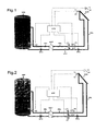
- the schematically illustrated solar system has a solar collector SOK, which is connected via a primary fluid circuit PKL to the primary side of a heat exchanger WAT.
- a primary pump PPU conveys a liquid, usually a water-methanol mixture in this closed primary circuit between the solar collector SOK and the primary side of the heat exchanger WAT.
- the latter may be formed, for example, as a plate exchanger.
- the solar collector SOK can consist of several units connected in parallel and / or in series.
- the secondary circuit SKL is connected on the one hand to the secondary side of the heat exchanger WAT and on the other hand to a water reservoir SPE, wherein a secondary pump SPU provides for the promotion of the water in the secondary circuit SKL.
- a secondary pump SPU provides for the promotion of the water in the secondary circuit SKL.
- the liquid circulating in the primary circuit PKL is constantly heated and releases its heat to the secondary circuit SKL via the heat exchanger WAT, heat storage being carried out in the reservoir SPE, i. H. the water in this memory SPE heats up.
- the water from the reservoir SPE or in the secondary circuit SKL can be used in a manner not shown here for heating purposes and / or as process water in a household or business.
- the corresponding connection fittings etc. are, as not essential to the invention, not shown here.
- a controller STE which switches on the system depending on various temperatures measured by sensors and quite generally controls various valves and pumps, which adjusts the operation of the system to the existing or desired temperatures.
- the control generated here is explained only insofar as it is related to the invention. In fact, the controller can have other tasks, especially in connection with the heat and water supply on the secondary side.
- the temperature T1 in the region of the solar collector SOK is measured with the aid of a sensor S1, and the corresponding measured value is fed to the controller STE.
- This sensor S2 can, for example, measure the temperature of the water present in the reservoir SPE at a selected location.
- a temperature sensor S3 the temperature T3 in the primary circuit is measured remotely from the solar collector SOK.
- a sun sensor S4 may be provided, which has a temperature T4 or one of the irradiation power, measured z. B. in W / m 2 , corresponding value.
- a three-way valve is inserted in the manner shown, which is also connected via a bypass BYP to the inlet of the heat exchanger WAT to the solar collector SOK.
- a check valve RSV is inserted between the bypass BYP and the heat exchanger WAT in the inlet.
- the controlled by the controller STE three-way valve V1 can be controlled so that it either completely free the return, so that caused by the pump PPU circulation between the solar collector SOK and the primary side of the heat exchanger WAT can go undisturbed.
- the valve can be controlled so that the primary side of the heat exchanger WAT is excluded by the bypass BYP from this cycle.
- the controller is now configured to start the primary pump PPU when the temperature T1 at the collector-side sensor S1 exceeds a temperature T2 measured with the memory-side sensor S2 by an adjustable magnitude.
- the start can additionally be made dependent on the fact that a predeterminable minimum temperature T1 at the sensor S1 has been reached. Now the water is pumped by the pump PPU in the primary circuit PKL.
- Another predefinable start condition is that the temperature or radiation value T4 detected by the sun sensor S4 exceeds a certain value and, moreover, the temperature T2 exceeds the temperature T1 by a certain amount.
- the temperature or radiation value T4 exceeds a specific value and, in addition, the temperature T1 in the collector region has a minimum value.
- the invention now uses here that when switching on the primary pump PPU the liquid does not flow through the primary side of the heat exchanger WAT, but by the correspondingly switched valve V1 via the bypass BYP on the heat exchanger WAT over again in the direction of solar collector SOK.
- the controller only switches over the valve V1 when the primary pump PPU has already been in operation for some time and until the temperature T3 measured with the sensor S3 has reached a value which excludes frost damage.
- the temperature T3 should, for example, not have minus degrees.
- the said time delay is necessary so that in the primary circuit PKL a reasonably stationary temperature state is reached.
- the temperatures may be very different when the solar collector SOK is outdoors and covered, for example, with ice or snow, whereas in general the three-way valve V1 and the primary pump PPU are in a more protected area, e.g. B. are arranged in a building.
- the temperature T3 it is additionally or alternatively possible to set the condition that the temperature T1 in the collector region has a certain minimum value
- the invention it is ensured that no cold liquid of the collector connection lines or snow covered collectors flows in the direction of the heat exchanger WAT and also a mistakenly manually switched primary pump PPU, the cold water-glycol mixture is no longer in the direction of insufficient sunlight Transport heat exchanger WAT and destroying the heat exchanger WAT is avoided.
- Destroying the heat exchanger by frost can not only destroy the heat exchanger WAT as such, but it could mix the pure water of the secondary circuit SKL with the water-glycol mixture of the primary circuit PKL, which ultimately freeze the piping of the primary circuit and the solar panels SOK and could be destroyed.
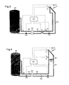
- Fig. 2 In the execution after Fig. 2 is another three-way valve V2 is provided and that at the other end of the bypass BYP in the lead of the primary circuit PKL.
- the three-way valve V1 off Fig. 1 is here designated by the reference symbol V1 '.
- Both three-way valves V1 'and V2 are controlled by the controller STE so that in the initial state after switching on the system, the primary pump PPU drives the liquid exclusively via the bypass BYP past the primary side of the heat exchanger WAT.
- the check valve RSV the Fig. 1 omitted. Incidentally, this embodiment is completely the same as that after Fig.1 ,
- Fig. 3 shows that instead of a three-way valve VI or two three-way valves V1 ', V2, a four-way valve V3 can be provided. Also, this valve V3 is controlled by the controller STE so that in the already described initial operating state, in which the liquid in the primary circuit PKL is still so cold that damage to the Heat exchanger WAT is to be feared, the liquid is pumped directly through the four-way valve V3 using the primary pump PPU, past the primary side of the heat exchanger WAT.
- the controller STE switches the four-way valve V3, so that the normal operating state is reached at which the liquid flows in the primary circuit PKL from the solar collector SOK directly to the primary side of the heat exchanger WAT and from here through the Pump PPU driven back to the solar collector SOK.
- the execution is the same as in the case of the Fig. 1 and 2 ,
- FIG. 4 A variant that uses no controllable valves in Fig. 4 shown.
- an additional pump namely an auxiliary pump HPU arranged at the solar collector SOK or in the vicinity in a bypass.
- auxiliary pump HPU When this auxiliary pump HPU is in operation, a cycle new solar collector SOK can be maintained.
- the temperature T3 is measured in this circuit, slightly away from the solar collector SOK, whereas the temperature T1 is measured in the immediate area of the solar collector SOK or at this.
- the control STE is thus set up to turn on the system according to the above-mentioned or other temperature-dependent starting conditions, for. B. turn on the auxiliary pump HPU when the temperature T1 at the collector near sensor S1, the measured temperature S2 with the memory SPE at the memory SPE exceeds by an adjustable size and when a minimum temperature T1 has been reached at the sensor S1. It is then the liquid in the primary circuit PKL pumped only in the described small circuit near the solar collector SOK.
- a check valve RSV as in FIG Fig. 4 shown to be prevented.
- an additional shut-off valve it is also possible to install an additional shut-off valve.
- the controller also has a differential control for the secondary circuit SKL, comparing the temperatures T3 and T2. As soon as the temperature T3 at the sensor S3 exceeds the temperature T2 which is measured at the memory SPE with the sensor S2 by an adjustable magnitude and a predetermined minimum temperature T3 at the sensor S3 is reached, the secondary pump SPU and the actual primary pump PPU switched on and the auxiliary pump HPU in the bypass BPA is turned off.
Landscapes
- Engineering & Computer Science (AREA)
- General Engineering & Computer Science (AREA)
- Chemical & Material Sciences (AREA)
- Thermal Sciences (AREA)
- Combustion & Propulsion (AREA)
- Mechanical Engineering (AREA)
- Physics & Mathematics (AREA)
- Life Sciences & Earth Sciences (AREA)
- Sustainable Development (AREA)
- Sustainable Energy (AREA)
- Air Conditioning Control Device (AREA)
- Other Air-Conditioning Systems (AREA)
- Control Of Temperature (AREA)
Claims (9)
- Installation solaire comprenant un collecteur ( SOK ) solaire, qui est relié par un circuit ( PKL ) primaire de liquide au côté primaire d'un échangeur de chaleur ( WAT ), comprenant un accumulateur ( SPE ), qui est relié par un circuit ( SKL ) secondaire de liquide au côté secondaire de l'échangeur de chaleur, comprenant une pompe ( PPU ) primaire dans le circuit primaire et une pompe ( SPU ) secondaire dans le circuit secondaire ainsi qu'une commande ( STE ) pour commander les pompes ( PPU, SPU ) en fonction de températures ( T1 ou T4 ) mesurées au moyen de capteurs ( S1, S2, S3, S4 ), au moins le circuit primaire pouvant être activé dès que des températures ( T4 ) mesurées ou leurs différences de température deviennent supérieures ou inférieures à des valeurs pouvant êtres prescrites,
caractérisée en ce que
la commande ( STE ) est telle, qu'après une invitation à l'activation du circuit primaire à l'aide d'un moyen ( V1, V1' + V2, HPU, V3 ) hydraulique, qu'elle maintient d'abord un circuit primaire auxiliaire, excluant au moins pour l'essentiel l'échangeur de chaleur ( WAT ), jusqu'à ce qu'une température ( T3, T1 ) mesurée au moyen d'un capteur ( S3, S1 ) dans la partie du circuit primaire et/ou du collecteur ( SOK ) dépasse une valeur excluant des dommages par le gel. - Installation solaire suivant la revendication 1, caractérisée en ce que le moyen hydraulique est un dispositif ( V1, V1' + V2, HPU, V3 ) de vanne dans le circuit primaire, par lequel le côté primaire de l'échangeur de chaleur ( WAT ) peut être court-circuité.
- Installation solaire suivant la revendication 2, caractérisée en ce que le dispositif de vanne est une vanne ( V1 ) à trois voies, à l'aide de laquelle le côté primaire de l'échangeur de chaleur peut être court-circuité par une dérivation ( BYP ).
- Installation solaire suivant la revendication 3, caractérisée en que la vanne ( V1 ) à trois voies se trouve dans le retour du circuit primaire et est reliée à la dérivation ( BYP ).
- Installation solaire suivant l'une des revendications 2 à 4, caractérisée en ce qu'un clapet anti-retour ( RSV ) est monté dans la partie d'entrée du circuit primaire du côté de l'échangeur de chaleur ( WAT ).
- Installation solaire suivant la revendication 2, caractérisée en ce que le dispositif à vanne est constitué de trois vannes ( V1', V2 ) à trois voies des deux côtés de la dérivation ( BYP ) qui, en étant commandées par la commande ( STE ), séparent, lors du court-circuitage du côté primaire de l'échangeur de chaleur ( WAT ), ce côté complètement de la partie du circuit primaire contenant le collecteur ( SOK ).
- Installation solaire suivant la revendication 2, caractérisée en ce que le dispositif à vanne est composé d'une vanne ( V3 ) à quatre voies qui, commandées par la commande ( STE ), sépare, lorsque le côté primaire de l'échangeur de chaleur ( WAT ) est court-circuité, ce côté primaire complètement de la partie du circuit ( PKL ) primaire contenant le collecteur ( SOK ) solaire.
- Installation solaire suivant la revendication 1, caractérisée en ce que, en plus de la pompe ( PPU ) du circuit primaire, il est prévu une pompe ( HPU ) primaire qui, après l'activation par la commande ( STE ), peut maintenir près du collecteur un circuit auxiliaire primaire excluant l'échangeur de chaleur ( WAT ) jusqu'à ce qu'une température ( Tel minimum soit atteinte dans la partie du collecteur.
- Installation solaire suivant la revendication 8, caractérisée en ce qu'un clapet anti-retour ( RSV ) est monté dans le circuit ( PKL ) primaire entre la pompe ( HPU ) auxiliaire et l'échangeur de chaleur ( WAT ).
Applications Claiming Priority (2)
| Application Number | Priority Date | Filing Date | Title |
|---|---|---|---|
| AT0055403A AT412505B (de) | 2003-04-09 | 2003-04-09 | Solaranlage |
| AT5542003 | 2003-04-09 |
Publications (3)
| Publication Number | Publication Date |
|---|---|
| EP1467155A2 EP1467155A2 (fr) | 2004-10-13 |
| EP1467155A3 EP1467155A3 (fr) | 2004-12-15 |
| EP1467155B1 true EP1467155B1 (fr) | 2009-09-30 |
Family
ID=32831418
Family Applications (1)
| Application Number | Title | Priority Date | Filing Date |
|---|---|---|---|
| EP04450079A Expired - Lifetime EP1467155B1 (fr) | 2003-04-09 | 2004-04-01 | Système solaire |
Country Status (3)
| Country | Link |
|---|---|
| EP (1) | EP1467155B1 (fr) |
| AT (2) | AT412505B (fr) |
| DE (1) | DE502004010143D1 (fr) |
Families Citing this family (4)
| Publication number | Priority date | Publication date | Assignee | Title |
|---|---|---|---|---|
| EP2009359B1 (fr) * | 2007-06-29 | 2016-09-14 | Vaillant GmbH | procédé de fonctionnement d'une installation thermique solaire |
| CN108266781A (zh) * | 2018-02-07 | 2018-07-10 | 北京民利储能技术有限公司 | 一种熔盐供暖装置 |
| CN111306609A (zh) * | 2020-02-27 | 2020-06-19 | 中国第一汽车股份有限公司 | 一种楼宇分时控制采暖温度节能系统 |
| CN112050282B (zh) * | 2020-09-09 | 2024-05-24 | 大连理工大学 | 智能感知热回收太阳能供暖屋顶系统 |
Family Cites Families (3)
| Publication number | Priority date | Publication date | Assignee | Title |
|---|---|---|---|---|
| DE2722451A1 (de) * | 1977-05-18 | 1978-11-30 | Bosch Gmbh Robert | Einrichtung zur waermeversorgung mit sonnenkollektoren |
| DE4006562A1 (de) * | 1990-03-02 | 1991-09-12 | Friedrich Mueller | Sonnenkollektoranlage und verfahren zum steuern einer solchen |
| WO1993002327A1 (fr) * | 1991-07-24 | 1993-02-04 | Rheem Australia Limited | Capteur solaire a protection contre le gel |
-
2003
- 2003-04-09 AT AT0055403A patent/AT412505B/de not_active IP Right Cessation
-
2004
- 2004-04-01 DE DE502004010143T patent/DE502004010143D1/de not_active Expired - Fee Related
- 2004-04-01 AT AT04450079T patent/ATE444470T1/de not_active IP Right Cessation
- 2004-04-01 EP EP04450079A patent/EP1467155B1/fr not_active Expired - Lifetime
Also Published As
| Publication number | Publication date |
|---|---|
| DE502004010143D1 (de) | 2009-11-12 |
| AT412505B (de) | 2005-03-25 |
| EP1467155A2 (fr) | 2004-10-13 |
| ATA5542003A (de) | 2004-08-15 |
| ATE444470T1 (de) | 2009-10-15 |
| EP1467155A3 (fr) | 2004-12-15 |
Similar Documents
| Publication | Publication Date | Title |
|---|---|---|
| EP3447403A1 (fr) | Procédures de fonctionnement pour installations de récupération de chaleur, unité d'échange de chaleur air/fluide et installation de récupération de chaleur | |
| EP1467155B1 (fr) | Système solaire | |
| DE102010017148A1 (de) | Verfahren zum Betreiben einer Wärmegewinnungsanlage | |
| DE102012102931A1 (de) | Wassergeführtes Solarsystem | |
| EP0444403B1 (fr) | Méthode pour contrôler une installation de capteurs solaires | |
| DE3035538A1 (de) | Anordnung zur aufnahme und speicherung von umweltwaerme zwecks beheizung und kuehlung von gebaeuden | |
| DE20301965U1 (de) | Steuervorrichtung für eine Solaranlage | |
| DE602004000871T2 (de) | Kombinierte Solarheizungsanlage mit Überhitzungsverwaltung und Verfahren zur Regulierung der Anlage. | |
| DE102014000671B4 (de) | Solaranlage und Verfahren zum Betreiben einer solchen | |
| EP2339245A2 (fr) | Dispositifs de chauffage et de refroidissement dotés d'une pompe à chaleur | |
| EP2405205B1 (fr) | Séparateur de gaz dans une installation solaire pour la production de chaleur | |
| EP2827082B1 (fr) | Procédé de commande d'un compresseur d'une pompe à chaleur | |
| EP2783164B1 (fr) | Procédé d'opération d'un système de conduite de fluide | |
| DE10254889B4 (de) | Regeltechnische Lösung für eine Wassererwärmungsanlage | |
| EP2778540B1 (fr) | Procédé et dispositif de chauffage de bâtiments par chauffage à infrarouge | |
| DE10341741A1 (de) | Solaranlage | |
| DE102008020637A1 (de) | Warmwasserversorgungsanlage mit einem Warmwasserspeicher | |
| AT509723B1 (de) | Frostschutzeinrichtung | |
| AT393555B (de) | Vorrichtung zur waermerueckgewinnung | |
| WO2009043334A2 (fr) | Absorbeur d'énergie air-solaire | |
| DE19804048A1 (de) | Solaranlage zur Wärmeerzeugung | |
| DE4123169C1 (en) | Frost protection for solar collectors - uses water replacing liq. on collector temp. dropping below preset level | |
| CH682011A5 (fr) | ||
| DE3043123C2 (de) | Heizungsanlage mit einer Wärmepumpe | |
| CH721935A1 (de) | Anlage zur wärmeversorgung eines gebäudes und betriebsverfahren |
Legal Events
| Date | Code | Title | Description |
|---|---|---|---|
| PUAI | Public reference made under article 153(3) epc to a published international application that has entered the european phase |
Free format text: ORIGINAL CODE: 0009012 |
|
| AK | Designated contracting states |
Kind code of ref document: A2 Designated state(s): AT BE BG CH CY CZ DE DK EE ES FI FR GB GR HU IE IT LI LU MC NL PL PT RO SE SI SK TR |
|
| AX | Request for extension of the european patent |
Extension state: AL HR LT LV MK |
|
| PUAL | Search report despatched |
Free format text: ORIGINAL CODE: 0009013 |
|
| AK | Designated contracting states |
Kind code of ref document: A3 Designated state(s): AT BE BG CH CY CZ DE DK EE ES FI FR GB GR HU IE IT LI LU MC NL PL PT RO SE SI SK TR |
|
| AX | Request for extension of the european patent |
Extension state: AL HR LT LV MK |
|
| RIC1 | Information provided on ipc code assigned before grant |
Ipc: 7F 24D 19/10 A Ipc: 7F 24J 2/46 B |
|
| 17P | Request for examination filed |
Effective date: 20050524 |
|
| AKX | Designation fees paid |
Designated state(s): AT BE BG CH CY CZ DE DK EE ES FI FR GB GR HU IE IT LI LU MC NL PL PT RO SE SI SK TR |
|
| GRAP | Despatch of communication of intention to grant a patent |
Free format text: ORIGINAL CODE: EPIDOSNIGR1 |
|
| GRAS | Grant fee paid |
Free format text: ORIGINAL CODE: EPIDOSNIGR3 |
|
| GRAA | (expected) grant |
Free format text: ORIGINAL CODE: 0009210 |
|
| AK | Designated contracting states |
Kind code of ref document: B1 Designated state(s): AT BE BG CH CY CZ DE DK EE ES FI FR GB GR HU IE IT LI LU MC NL PL PT RO SE SI SK TR |
|
| REG | Reference to a national code |
Ref country code: GB Ref legal event code: FG4D Free format text: NOT ENGLISH Ref country code: CH Ref legal event code: EP |
|
| REG | Reference to a national code |
Ref country code: CH Ref legal event code: NV Representative=s name: SIEMENS SCHWEIZ AG |
|
| REG | Reference to a national code |
Ref country code: IE Ref legal event code: FG4D |
|
| REF | Corresponds to: |
Ref document number: 502004010143 Country of ref document: DE Date of ref document: 20091112 Kind code of ref document: P |
|
| PG25 | Lapsed in a contracting state [announced via postgrant information from national office to epo] |
Ref country code: SE Free format text: LAPSE BECAUSE OF FAILURE TO SUBMIT A TRANSLATION OF THE DESCRIPTION OR TO PAY THE FEE WITHIN THE PRESCRIBED TIME-LIMIT Effective date: 20090930 Ref country code: FI Free format text: LAPSE BECAUSE OF FAILURE TO SUBMIT A TRANSLATION OF THE DESCRIPTION OR TO PAY THE FEE WITHIN THE PRESCRIBED TIME-LIMIT Effective date: 20090930 |
|
| PG25 | Lapsed in a contracting state [announced via postgrant information from national office to epo] |
Ref country code: PL Free format text: LAPSE BECAUSE OF FAILURE TO SUBMIT A TRANSLATION OF THE DESCRIPTION OR TO PAY THE FEE WITHIN THE PRESCRIBED TIME-LIMIT Effective date: 20090930 Ref country code: SI Free format text: LAPSE BECAUSE OF FAILURE TO SUBMIT A TRANSLATION OF THE DESCRIPTION OR TO PAY THE FEE WITHIN THE PRESCRIBED TIME-LIMIT Effective date: 20090930 |
|
| NLV1 | Nl: lapsed or annulled due to failure to fulfill the requirements of art. 29p and 29m of the patents act | ||
| PG25 | Lapsed in a contracting state [announced via postgrant information from national office to epo] |
Ref country code: RO Free format text: LAPSE BECAUSE OF FAILURE TO SUBMIT A TRANSLATION OF THE DESCRIPTION OR TO PAY THE FEE WITHIN THE PRESCRIBED TIME-LIMIT Effective date: 20090930 Ref country code: PT Free format text: LAPSE BECAUSE OF FAILURE TO SUBMIT A TRANSLATION OF THE DESCRIPTION OR TO PAY THE FEE WITHIN THE PRESCRIBED TIME-LIMIT Effective date: 20100201 Ref country code: ES Free format text: LAPSE BECAUSE OF FAILURE TO SUBMIT A TRANSLATION OF THE DESCRIPTION OR TO PAY THE FEE WITHIN THE PRESCRIBED TIME-LIMIT Effective date: 20100110 Ref country code: EE Free format text: LAPSE BECAUSE OF FAILURE TO SUBMIT A TRANSLATION OF THE DESCRIPTION OR TO PAY THE FEE WITHIN THE PRESCRIBED TIME-LIMIT Effective date: 20090930 Ref country code: CZ Free format text: LAPSE BECAUSE OF FAILURE TO SUBMIT A TRANSLATION OF THE DESCRIPTION OR TO PAY THE FEE WITHIN THE PRESCRIBED TIME-LIMIT Effective date: 20090930 |
|
| REG | Reference to a national code |
Ref country code: IE Ref legal event code: FD4D |
|
| PG25 | Lapsed in a contracting state [announced via postgrant information from national office to epo] |
Ref country code: SK Free format text: LAPSE BECAUSE OF FAILURE TO SUBMIT A TRANSLATION OF THE DESCRIPTION OR TO PAY THE FEE WITHIN THE PRESCRIBED TIME-LIMIT Effective date: 20090930 Ref country code: CY Free format text: LAPSE BECAUSE OF FAILURE TO SUBMIT A TRANSLATION OF THE DESCRIPTION OR TO PAY THE FEE WITHIN THE PRESCRIBED TIME-LIMIT Effective date: 20090930 |
|
| PG25 | Lapsed in a contracting state [announced via postgrant information from national office to epo] |
Ref country code: NL Free format text: LAPSE BECAUSE OF FAILURE TO SUBMIT A TRANSLATION OF THE DESCRIPTION OR TO PAY THE FEE WITHIN THE PRESCRIBED TIME-LIMIT Effective date: 20090930 Ref country code: IE Free format text: LAPSE BECAUSE OF FAILURE TO SUBMIT A TRANSLATION OF THE DESCRIPTION OR TO PAY THE FEE WITHIN THE PRESCRIBED TIME-LIMIT Effective date: 20090930 Ref country code: DK Free format text: LAPSE BECAUSE OF FAILURE TO SUBMIT A TRANSLATION OF THE DESCRIPTION OR TO PAY THE FEE WITHIN THE PRESCRIBED TIME-LIMIT Effective date: 20090930 |
|
| PLBE | No opposition filed within time limit |
Free format text: ORIGINAL CODE: 0009261 |
|
| STAA | Information on the status of an ep patent application or granted ep patent |
Free format text: STATUS: NO OPPOSITION FILED WITHIN TIME LIMIT |
|
| PGFP | Annual fee paid to national office [announced via postgrant information from national office to epo] |
Ref country code: AT Payment date: 20100310 Year of fee payment: 7 |
|
| 26N | No opposition filed |
Effective date: 20100701 |
|
| PG25 | Lapsed in a contracting state [announced via postgrant information from national office to epo] |
Ref country code: GR Free format text: LAPSE BECAUSE OF FAILURE TO SUBMIT A TRANSLATION OF THE DESCRIPTION OR TO PAY THE FEE WITHIN THE PRESCRIBED TIME-LIMIT Effective date: 20091231 |
|
| BERE | Be: lapsed |
Owner name: SIEMENS AG OSTERREICH Effective date: 20100430 |
|
| PG25 | Lapsed in a contracting state [announced via postgrant information from national office to epo] |
Ref country code: MC Free format text: LAPSE BECAUSE OF NON-PAYMENT OF DUE FEES Effective date: 20100430 |
|
| REG | Reference to a national code |
Ref country code: CH Ref legal event code: PL |
|
| GBPC | Gb: european patent ceased through non-payment of renewal fee |
Effective date: 20100401 |
|
| REG | Reference to a national code |
Ref country code: FR Ref legal event code: ST Effective date: 20101230 |
|
| PG25 | Lapsed in a contracting state [announced via postgrant information from national office to epo] |
Ref country code: LI Free format text: LAPSE BECAUSE OF NON-PAYMENT OF DUE FEES Effective date: 20100430 Ref country code: DE Free format text: LAPSE BECAUSE OF NON-PAYMENT OF DUE FEES Effective date: 20101103 Ref country code: CH Free format text: LAPSE BECAUSE OF NON-PAYMENT OF DUE FEES Effective date: 20100430 |
|
| PG25 | Lapsed in a contracting state [announced via postgrant information from national office to epo] |
Ref country code: GB Free format text: LAPSE BECAUSE OF NON-PAYMENT OF DUE FEES Effective date: 20100401 Ref country code: IT Free format text: LAPSE BECAUSE OF FAILURE TO SUBMIT A TRANSLATION OF THE DESCRIPTION OR TO PAY THE FEE WITHIN THE PRESCRIBED TIME-LIMIT Effective date: 20090930 Ref country code: BE Free format text: LAPSE BECAUSE OF NON-PAYMENT OF DUE FEES Effective date: 20100430 |
|
| REG | Reference to a national code |
Ref country code: AT Ref legal event code: MM01 Ref document number: 444470 Country of ref document: AT Kind code of ref document: T Effective date: 20110401 |
|
| PG25 | Lapsed in a contracting state [announced via postgrant information from national office to epo] |
Ref country code: AT Free format text: LAPSE BECAUSE OF NON-PAYMENT OF DUE FEES Effective date: 20110401 |
|
| PG25 | Lapsed in a contracting state [announced via postgrant information from national office to epo] |
Ref country code: FR Free format text: LAPSE BECAUSE OF NON-PAYMENT OF DUE FEES Effective date: 20100430 |
|
| PG25 | Lapsed in a contracting state [announced via postgrant information from national office to epo] |
Ref country code: HU Free format text: LAPSE BECAUSE OF FAILURE TO SUBMIT A TRANSLATION OF THE DESCRIPTION OR TO PAY THE FEE WITHIN THE PRESCRIBED TIME-LIMIT Effective date: 20100401 Ref country code: BG Free format text: LAPSE BECAUSE OF FAILURE TO SUBMIT A TRANSLATION OF THE DESCRIPTION OR TO PAY THE FEE WITHIN THE PRESCRIBED TIME-LIMIT Effective date: 20090930 Ref country code: LU Free format text: LAPSE BECAUSE OF NON-PAYMENT OF DUE FEES Effective date: 20100401 |
|
| PG25 | Lapsed in a contracting state [announced via postgrant information from national office to epo] |
Ref country code: TR Free format text: LAPSE BECAUSE OF FAILURE TO SUBMIT A TRANSLATION OF THE DESCRIPTION OR TO PAY THE FEE WITHIN THE PRESCRIBED TIME-LIMIT Effective date: 20090930 |