EP1467190A2 - Device for continuous dosing and for pneumatically conveying of free-flowing products. - Google Patents
Device for continuous dosing and for pneumatically conveying of free-flowing products. Download PDFInfo
- Publication number
- EP1467190A2 EP1467190A2 EP04008550A EP04008550A EP1467190A2 EP 1467190 A2 EP1467190 A2 EP 1467190A2 EP 04008550 A EP04008550 A EP 04008550A EP 04008550 A EP04008550 A EP 04008550A EP 1467190 A2 EP1467190 A2 EP 1467190A2
- Authority
- EP
- European Patent Office
- Prior art keywords
- pressure
- control
- metering
- discharge
- container
- Prior art date
- Legal status (The legal status is an assumption and is not a legal conclusion. Google has not performed a legal analysis and makes no representation as to the accuracy of the status listed.)
- Granted
Links
Images


Classifications
-
- G—PHYSICS
- G01—MEASURING; TESTING
- G01G—WEIGHING
- G01G11/00—Apparatus for weighing a continuous stream of material during flow; Conveyor belt weighers
- G01G11/08—Apparatus for weighing a continuous stream of material during flow; Conveyor belt weighers having means for controlling the rate of feed or discharge
-
- B—PERFORMING OPERATIONS; TRANSPORTING
- B29—WORKING OF PLASTICS; WORKING OF SUBSTANCES IN A PLASTIC STATE IN GENERAL
- B29B—PREPARATION OR PRETREATMENT OF THE MATERIAL TO BE SHAPED; MAKING GRANULES OR PREFORMS; RECOVERY OF PLASTICS OR OTHER CONSTITUENTS OF WASTE MATERIAL CONTAINING PLASTICS
- B29B7/00—Mixing; Kneading
- B29B7/02—Mixing; Kneading non-continuous, with mechanical mixing or kneading devices, i.e. batch type
- B29B7/22—Component parts, details or accessories; Auxiliary operations
- B29B7/24—Component parts, details or accessories; Auxiliary operations for feeding
- B29B7/242—Component parts, details or accessories; Auxiliary operations for feeding in measured doses
-
- B—PERFORMING OPERATIONS; TRANSPORTING
- B29—WORKING OF PLASTICS; WORKING OF SUBSTANCES IN A PLASTIC STATE IN GENERAL
- B29B—PREPARATION OR PRETREATMENT OF THE MATERIAL TO BE SHAPED; MAKING GRANULES OR PREFORMS; RECOVERY OF PLASTICS OR OTHER CONSTITUENTS OF WASTE MATERIAL CONTAINING PLASTICS
- B29B7/00—Mixing; Kneading
- B29B7/30—Mixing; Kneading continuous, with mechanical mixing or kneading devices
- B29B7/58—Component parts, details or accessories; Auxiliary operations
- B29B7/60—Component parts, details or accessories; Auxiliary operations for feeding, e.g. end guides for the incoming material
Definitions
- the metering device with the Kontrollmeß has the additional advantage that thereby the measuring accuracy even with dosing with a weighed Dosierzellenradschleuse or a Coriolis flowmeter or other gravimetric dosing can be advantageously improved. It arises in particular in the coal dust metering the advantage that by the simple control containers themselves the effort to gravimetric Dosing devices without static control devices not significantly increased, although thereby the dosing accuracy Overall, can be significantly improved.
- a coal dust dosing device for a flow rate
- 20 t / h is preferably a cylindrical trained control container 3 is provided, which is a vertical Height of about 2 m.
- the control container 3 has a Inlet opening of approx. 700 mm inside diameter with an outside diameter of the control container of approx. 1,000 mm.
- At the bottom is additionally an agitator arranged the coal dust 4 evenly into one underneath provided discharge, which as Austragszellenradschleuse 5 is formed.
- the control container 3 is supported on a connecting edge 14 on preferably three load cells 7 from the force receiving side resting on a stationary support frame 13.
- the load cells 7 could also be below the entire dosing between arranged the support frame 13 and the footprint 15 be, if this is advantageous for constructive reasons.
- the gate valve 2 whole or at least partially open, so that the control container 3 always is filled up in the Vorsilo Scheme and through its dense Content in the control tank 3 entering scoop and air leakage largely seals against the Vorsilo 1.
- the control container 3 with a cover plate closed to the arranged underneath Austragszellenradschleuse 5 has at least one outlet opening.
- Austragszellenradschleuse 5 These Outlet opening coincides with an inlet opening underneath arranged Austragszellenradschleuse 5.
- the control container 3 can also down through the cover plate of Austragszellenradschleuse 5 are closed, with the bottom edge 16 of the control container 3 is screwed.
- the Austragszellenradschleuse 5 is designed as a horizontal rotary feeder, the pulverized coal 4 to be discharged from an inlet port by means of a driven impeller over an angular range from about 180 ° to an outlet area, through which the coal dust 4 down into the pneumatic Delivery line 12 fails.
- a pressure-controlled dosage with a recalibration provided by the Kontrollmeß To is in the delivery line 12 between the blower and the pulverized coal discharge point an unillustrated pressure transducer P3 installed, which detects the pressure in the delivery line 12.
- a pressure-controlled dosage can be achieved by a differential pressure measurement in a homogeneous conveyor line part still improved be, in which as little as possible counselturbulenzen occur.
- the ideal relationship between the pressure in the delivery line 12 and the discharged flow rate is in the Practice of factors such as the conveying air temperature, the pressure differences in the rotary valve 5 and in the control tank 3 and with the associated flow conditions influenced, so that still a compensation circuit 21 is provided as an electronic calculation circuit.
- this compensation circuit 21 is at least one electronic pressure compensation, in particular the pressure differences considered at the discharge or Dosierzellenradschleuse 5.
- This is at the outlet of the lock 5 another Pressure sensor P1 and in the control tank 3 an additional Pressure transducer P2 provided with the compensation circuit 21 are connected. This is given a calculation algorithm, the influence of pressure conditions on the actual flow rate equivalent.
- the characteristic values for this are the compensation circuit 21 given or due to a test operation determined.
- Such a delivery rate control can also be implemented with a microwave or ultrasonic detection in the delivery line 12 respectively. This is done via a microwave or Ultraschallauf Struktur admirados the distribution density of air and Coal dust on a cross-sectional portion in the conveyor pipe 12th detected and from it in a pickup the actual delivery rate calculated. This can then turn as a reference variable be used for the controller 23.
- the invention proposes a gravimetric Kontrollmeßhabilit before, the Recalibration of the pressure-dependent or distribution-dependent Flow rate control is used.
- This is a Kontrollmeß raised provided, at least from the weighed control container 3 with large inlet opening and about the same size Flow area with subsequent metering and an electronic calculation circuit as Kontrollmeßscrien 22 for electronic pressure compensation exists.
- This is as dosing usually a horizontal rotary valve 5 provided which is weighed with and over a smaller outlet cross-section the bulk materials 4 discharges into the delivery line 12.
- the problem is that by the overpressure in the delivery line 12 in a static control measurement additional forces acting on the load cells 7, the can distort this weighing result.
- Such a metering device with a Dosierzellenradschleuse 5 is through the always filled control container. 3 also with no additional pressure decoupling to the delivery line a relatively high discharge pressure up to about 0.6 bar operable. This is mainly possible because the always filled Control container 3 a high sealing effect against the atmospheric pressure in Vorsilo 1, so that the Dosierkonstanz guaranteed even at relatively high delivery pressures remains, since little air leakage affects the Dosieraustrag.
- the Dosierzellenradschleuse 25 serves as a gravimetric dosing, in the so-called block operation is operated with the Austragszellenradschleuse 5.
- the drive speed of the Austragszellenradschleuse 5 regulated so that the loading of the weighed Dosierzellenradschleuse 25 remains constant, with the Austragszellenradschleuse 5 does not promote in overflow operation. This will be in Basically achieved in that the filling tube 24 up to a predetermined Fill level remains approximately constant.
- the checkweighing for the upper level calculates the Kontrollmeßscaria 22 a static weight value, the order the force effect is corrected by the delivery pressure. A Such weight determination also takes place for the lower one Level value. From the two corrected static weight values and the discharge period between the weight value detection the control measuring circuit 22 calculates a Feed rate value. This static flow control value is fed to the actual value circuit and there with the continuous counselwaysnistwert compared and at a Deviation another correction factor or value determined in addition to the future continuous actual value results corrected and corrected as described above become.
- Such a control measurement requires about a control time of a minute, in which about a control amount of 300 kg Carbon dust be discharged from the control tank 3.
- a Such control measurement can at any time intervals or for other reasons to improve the dosing accuracy be repeated. Because of the replenishment of the Control container 3, the gravimetric dosing with Dosierzellenradschleuse 25 can not be affected the continuous gravimetric dosing by the static Checkweighing not affected.
Landscapes
- Physics & Mathematics (AREA)
- General Physics & Mathematics (AREA)
- Filling Or Emptying Of Bunkers, Hoppers, And Tanks (AREA)
- Weight Measurement For Supplying Or Discharging Of Specified Amounts Of Material (AREA)
- Air Transport Of Granular Materials (AREA)
- Chutes (AREA)
- Vending Machines For Individual Products (AREA)
Abstract
Die Erfindung betrifft eine Vorrichtung zum Dosieren und pneumatischen
Fördern von schüttfähigen Gütern mit einem Vorsilo
(1) und daran befestigten Absperrschieber (2), an dem eine
statische Kontrollmeßeinrichtung zur Nachkalibrierung einer
kontinuierlichen Dosierung vorgesehen ist. Dazu ist ein verwogener
Kontrollbehälter (3) kraftnebenschlußfrei am Vorsilo (1)
befestigt. Der Kontrollbehälter (3) ist mindestens mit einem
Austrags- (5) und/oder Dosierorgan (25) verbunden, durch das
ein dosierter Austrag in eine pneumatische Förderleitung (12)
erfolgt. Die Erfindung ist dadurch gekennzeichnet, daß der
Kontrollbehälter (3) eine Einlaßöffnung mit großem Einlaßquerschnitt
aufweist, der etwa seinem Behälterquerschnitt entspricht.
Die Kontrollmeßeinrichtung enthält dabei Ausgleichsmittel,
durch die die Kraftwirkungen auf die statische Kontrollwägeeinrichtung
durch die Druckunterschiede zwischen der
Förderleitung (12) und dem Absperrschieber (2) während der
Kontrollmessung ausgeglichen und/oder kompensiert werden.
Description
Die Erfindung betrifft eine Vorrichtung zum kontinuierlichen
Dosieren und pneumatischen Fördern von schüttfähigen Gütern
gemäß dem Oberbegriff des Patentanspruchs 1 und 14.The invention relates to a device for continuous
Dosing and pneumatic conveying of pourable goods
according to the preamble of
In industriellen Herstellungs- und Verarbeitungsverfahren werden vielfach Schüttgüter dosiert zugegeben. Dazu können sie nicht immer dem Herstellungs- oder Verarbeitungsprozeß direkt zugeführt werden, sondern werden häufig über pneumatische Förderleitungen zum Herstellungs- oder Verarbeitungsort transportiert. Die Schüttgüter werden dazu in der Regel aus einem Silo oder anderen Vorratsbehältern abgezogen und über Dosiervorrichtungen in eine pneumatische Förderleitung eingeleitet. In die Förderleitung wird dabei mittels eines Gebläses meist eine kontinuierliche Förderluftmenge eingeblasen, die im wesentlichen von der vorgesehenen maximalen Förderstärke, dem Förderleitungsquerschnitt und der Länge der Förderstrecke abhängig ist.In industrial manufacturing and processing methods In many cases bulk materials added in doses. They can do that not always directly to the manufacturing or processing process are fed but often via pneumatic delivery lines transported to the production or processing. The bulk materials are usually from a silo or other storage tanks withdrawn and dosing devices introduced into a pneumatic conveying line. In the delivery line is usually a by means of a blower blown continuous conveying air, which is substantially from the intended maximum delivery, the delivery line cross-section and the length of the conveyor line dependent is.
Insbesondere bei der Herstellung von Zement, Kalk, Gips und anderen Keramikmaterialien wird über eine pneumatische Förderleitung schüttfähiger Brennstoff wie Kohlenstaub dosiert in einen Brennofen mit einer pneumatischen Förderleitung eingeblasen, um eine bestimmte Verarbeitungstemperatur zu erzeugen. Dabei muß die dosierte Brennstoffzugabe sehr gleichmäßig und genau erfolgen, um Temperaturschwankungen und eine unwirtschaftliche Verbrennung sowie erhöhte Verbrennungsrückstände zu vermeiden. Especially in the production of cement, lime, gypsum and other ceramic materials is via a pneumatic delivery line pourable fuel such as coal dust dosed into injected a kiln with a pneumatic delivery line, to produce a certain processing temperature. The metered addition of fuel must be very evenly and be done precisely to temperature fluctuations and an uneconomical Combustion and increased combustion residues to avoid.
Eine derartige Vorrichtung zur kontinuierlichen Dosierung von Schüttgütern in eine pneumatische Förderleitung ist aus der DE 32 17 407 C2 bekannt. Dazu wird eine gravimetrische Dosierung mit einem Dosierrotor vorgeschlagen, der unter einem Vorratsbehälter bzw. Silo angeordnet ist. Aus dem Silo werden die Schüttgüter mit einer Austragszellenradschleuse abgezogen und in eine Aufgabeöffnung des Dosierrotors eingefüllt. Der Dosierrotor dreht sich dabei um eine vertikale Achse bis die Rotortaschen bzw. -kammern nach ca. 345° über einer Entleerungsöffnung angelangt sind. Die Entleerungsöffnung ist durchgängig mit einer pneumatischen Förderleitung verbunden, an die ein Gebläse angeschlossen ist, so daß die Schüttgüter vertikal aus der Entleerungsöffnung ausgeblasen und insbesondere einem Verbrennungsofen zugeführt werden. Der Rotor ist dabei über einen Hebelarm gelenkig an Wägezellen aufgehängt, so daß er die geförderte Schüttgutmenge gewichtsmäßig erfaßt. Aus der erfaßten Fördermenge einer Rotorumdrehung wird in einer Auswertevorrichtung die Ist-Förderstärke errechnet, die mit einer vorgegebenen Soll-Förderstärke verglichen und bei einer Abweichung die Rotordrohzahl entsprechend geregelt wird, um eine kontinuierliche Förderstärke aufrecht zu erhalten. Eine derartige gravimetrische Dosierung mit einem Dosierrotor ist apparativ sehr aufwendig, da die pneumatische Förderleitung vertikal durch den Rotor geführt werden muß und über kraftnebenschlußfreie flexible Anschlußteile am Rotor zu befestigen ist. Des weiteren ist zwischen dem Silo und dem Dosierrotor zur druckmäßigen Entkopplung noch eine zusätzliche Zellenradschleuse vorgesehen, die den apparativen Aufwand der gravimetrischen Dosierung und pneumatischen Förderung zusätzlich erhöht.Such a device for the continuous dosing of Bulk goods in a pneumatic conveying line is from the DE 32 17 407 C2 known. This is a gravimetric dosage proposed with a metering rotor, which is under a storage tank or silo is arranged. From the silo are the Drained bulk goods with a Austragszellenradschleuse and filled in a feed opening of the dosing rotor. The dosing rotor turns around a vertical axis until the rotor pockets or chambers after about 345 ° above a discharge opening arrived. The emptying opening is continuous connected to a pneumatic conveying line, to the one Blower is connected so that the bulk solids are vertical the emptying opening blown out and in particular a Incinerator be supplied. The rotor is over a lever arm hinged to load cells, so that he the amount of bulk transported weighted detected. From the detected flow rate of a rotor rotation is in an evaluation device the actual flow rate calculated with a predetermined target flow rate compared and a deviation the Rotordrohzahl is regulated according to a to maintain continuous flow. Such Gravimetric dosing with a dosing rotor is apparative very expensive, because the pneumatic conveying line vertical must be performed by the rotor and kraftkraftbenbenfreie flexible connection parts to be attached to the rotor. Furthermore, between the silo and the dosing to the pressure-related decoupling nor an additional rotary valve provided that the equipment expense of gravimetric Dosage and pneumatic conveying additionally increased.
Bei einer derartigen Kohlenstaubdosiervorrichtung muß der Rotor aus Sicherheitsgründen auch vorgegebenen Überdrücken standhalten, so daß wegen dieser mechanischen Festigkeitsvorgaben die verwogenen Teile verhältnismäßig schwer ausgebildet sein müssen. Daraus folgt bei einer gravimetrischen Dosierung ein wägetechnisch ungünstiges Verhältnis des Nutzgewichts zum Taragewicht, wobei die Wägegenauigkeit auch noch durch rotatorisch bedingte Beschleunigungskräfte ungünstig beeinflußt werden kann.In such Kohlenstaubdosiervorrichtung the rotor for safety reasons also given overpressures withstand so that because of these mechanical strength specifications the weighed parts are relatively heavy have to be. It follows with a gravimetric dosage a weighing technically unfavorable ratio of the useful weight to Tare weight, whereby the weighing accuracy is also rotatory conditional acceleration forces are adversely affected can.
Zur Verbesserung der Meßgenauigkeit derartiger gravimetrischer
Dosierverfahren ist aus dem Fachaufsatz von Häfner und Wolfschaffner,
Dosierrotorwaagen - die universelle Lösung, in der
Fachzeitschrift wägen+dosieren, Heft 6, 1996, Seiten 26 bis 34
ein Blocksystem mit statischer Kontrollwägung bekannt, durch
die die kontinuierliche gravimetrische Dosierung in vorgegebenen
zeitlichen Abständen nachkalibriert werden kann. Dazu ist
zwischen dem Silo und der Austragszellenradschleuse des Dosierrotors
ein zusätzlicher Kontrollbehälter angeordnet, der
von der Zellenradschleuse des Silos kontinuierlich befüllt
wird. Dieser Kontrollbehälter stellt einen separaten Vorratsbehälter
dar, der an seinem querschnittsgroßen Oberteil eine
kleine Zuführöffnung besitzt und sich zum Auslaßbereich konisch
verjüngt und meist noch ein zusätzliches Rührwerk enthält.
Dieser Kontrollbehälter ist über die Austragszellenradschleuse
mit dem Dosierrotor verbunden und das ganze stützt
sich auf vier Wägezellen zu einer statischen Kontrollwägung
ab. In vorgegebenen Zeitabständen wird der verwogene Kontrollbehälter
durch ein Absperrorgan am Silo von der weiteren Befüllung
getrennt und zwischen einem oberen und einem unteren
Füllstand statisch verwogen. Die statische Gewichtsdifferenz
dieser beiden Messungen wird dann mit der in dieser Zeit dynamisch
ermittelten Dosiermenge verglichen und bei einer Abweichung
eine Nachkalibrierung der dynamischen Dosierung vorgenommen.To improve the accuracy of such gravimetric
Dosing method is from the technical article by Häfner and Wolfschaffner,
Dosing rotor scales - the universal solution in which
Specialist magazine Weighing + Dosing,
Eine derartige statische Kontrollwägung ist systembedingt allerdings auch mit einem Meßfehler behaftet, der durch eine möglichst große Kontrollmenge und einen verhältnismäßig großen Vergleichszeitraum gering gehalten werden kann. Dies erfordert aber einen aufwendig großen Zwischenbehälter, der in der Kontrollmeßzeit durch Leck- und Schöpfluft mit Förderdruck beaufschlagt wird. Um gleichsam eine kontinuierliche Dosierung beim luftdichten Abschluß des Kontrollbehälters vom Silo zu gewährleisten, ist der Kontrollbehälter in seinem oberen Bereich über ein zusätzliches Filter mit der Atmosphäre verbunden. Dies erfordert nicht nur einen zusätzlichen apparativen Aufwand, sondern erzeugt auch noch eine Meßwertverfälschung der statischen Kontrollwägung, die durch den Förderdruck entsteht, die der Gewichtskraft entgegenwirkt und somit im statischen Gewichtssignal enthalten ist. Da dieser Differenzdruck zwischen dem Förderdruck und dem im Kontrollbehälter herrschenden Atmosphärendruck sowohl von der jeweiligen Förderstärke als auch der Förderlufttemperatur abhängig ist, kann dieser Fehler nur schwer vermieden werden.However, such a static checkweighing is systemic Also subject to a measurement error by a the largest possible amount of control and a relatively large Comparison period can be kept low. This requires but a lavishly large intermediate container, in the Kontrollmeßzeit through leakage and Schöpfluft subjected to delivery pressure becomes. As it were a continuous dosage in the to ensure airtight closure of the control container from the silo, is the control tank in its upper area connected to the atmosphere via an additional filter. This not only requires additional equipment, but also generates a Meßwertverfälschung the static checkweighing, which results from the delivery pressure, which counteracts the weight and thus in the static Weight signal is included. Because this differential pressure between the delivery pressure and the prevailing in the control container Atmospheric pressure both from the respective flow rate also depends on the delivery air temperature, this error can difficult to avoid.
Aus der EP 0 644 406 B1 ist zwar eine kontinuierliche gravimetrische Dosiervorrichtung bekannt, die diese Druckverhältnisse in einem derartigen verwogenen Vorratsbehälter mit Druckaufnehmern überwacht und erst dann eine Gewichtsmessung durchführt, wenn kein Druckunterschied mehr feststellbar ist. Dies ist aber bei einer kontinuierlichen Dosierung in einem pneumatischen Förderweg mit Überdruck nur durch aufwendige Geräte zur Druckentkopplung wie Staubpumpen und dergleichen möglich, da bei Dosierorganen Leckluft oder Schöpfluftanteile meist nicht auszuschließen sind.From EP 0 644 406 B1, although a continuous gravimetric Metering device known, these pressure conditions in such a weighed reservoir with pressure transducers monitored and only then performs a weight measurement, when no pressure difference is detectable. This but is in a continuous dosing in a pneumatic Conveyor with overpressure only by consuming devices for pressure decoupling such as dust pumps and the like possible, because of dosing organs leak air or Schöpfluftanteile usually can not be ruled out.
Aus der DE 44 43 053 A1 ist ein weiteres Verfahren und eine Vorrichtung zur kontinuierlichen gravimetrischen Dosierung und Massenstrombestimmung von fließfähigen Gütern bekannt. Zur gravimetrischen Dosierung ist dabei ein Durchflußmeßgerät mit einem Coriolis-Meßrad vorgesehen, das eine schnelle Gewichtsermittlung des durchfließenden Schüttgutstromes ermöglicht und in seiner Ausgestaltung weniger aufwendig ist als ein Dosierrotor. Allerdings erfordert diese Dosiervorrichtung zum Austrag in die pneumatische Förderleitung eine zusätzliche Zellenradschleuse als Dosierorgan, deren Drehzahl von der Durchflußmeßvorrichtung gesteuert wird. Bei einer Brennstoffdosierung in eine Feuerungsanlage soll die zusätzliche Zellenradschleuse jedoch entbehrlich sein und direkt in die Förderleitung dosiert werden können. Dazu muß dann aber das Fördergebläse in seiner Luftmenge regelbar sein. Bei höheren Förderstärken erhöht sich dabei aber der Druck im Gehäuse der Durchflußmeßvorrichtung und an der Abzugszellenradschleuse, so daß an dieser erhöhte Leckluft und Schöpfluft in den Vorratsbehälter eingeleitet wird. Dadurch entsteht wiederum ein ungleichmäßigerer Austrag aus der Zellenradschleuse, wodurch zur Druckentkopplung zur Förderleitung wiederum eine Staubpumpe oder eine zusätzliche Zellenradschleuse notwendig ist. Dadurch erhöht sich der apparative Aufwand wiederum erheblich und fordert zudem noch zusätzlichen Bauraum.From DE 44 43 053 A1 is another method and a Apparatus for continuous gravimetric dosing and Mass flow determination of flowable goods known. to Gravimetric dosing is a flowmeter with a Coriolis measuring wheel, which provides a fast weight determination allows the flowing bulk flow and in its embodiment is less expensive than a metering rotor. However, this metering device requires discharge in the pneumatic conveying line an additional rotary valve as metering, whose speed of the flow measuring is controlled. With a fuel metering in a firing system is the additional rotary valve However, be dispensable and directly into the support line can be dosed. For this purpose, but then the conveyor fan be adjustable in its air flow. At higher flow rates but it increases the pressure in the housing of the flowmeter and at the Abzugszellenradschleuse, so that at this increased air leakage and Schöpfluft in the reservoir is initiated. This in turn creates a more uneven Discharge from the rotary valve, causing the Pressure decoupling to the delivery line again a dust pump or an additional rotary valve is necessary. Thereby in turn, the expenditure on equipment increases considerably and demands also additional space.
Derartige gravimetrische Dosiereinrichtungen mit Coriolis-Durchflußmessern verfügen auch nicht immer über die notwendige Langzeitgenauigkeit, so daß auch dort häufig eine statische Kontrollmeßvorrichtung vorgesehen wird. Deshalb sind auch bei Coriolis-Durchflußmessern aus Genauigkeitsgründen teilweise verwogene Zwischenbehälter wie bei Dosierrotoren notwendig, die zur Nachkalibrierung eingesetzt werden. Auch derartige statische Kontrollwägeeinrichtungen erhöhen den apparativen Aufwand erheblich und erfordern noch zusätzlichen Bauraum, der insbesondere in der Höhe häufig nicht zur Verfügung steht.Such gravimetric metering devices with Coriolis flowmeters also do not always have the necessary Long-term accuracy, so that often there is a static Control measuring device is provided. That's why Coriolis flowmeters partially for accuracy reasons weighed intermediate container as with dosing rotors necessary which are used for recalibration. Also such static checkweighing devices increase the apparative Expenditure considerably and still require additional space, the especially in height is often not available.
Zur Verbesserung der Dosierkonstanz in pneumatische Förderleitungen ist aus der DE 197 49 873 A1 eine Doppelschleusensystem mit dazwischen angeordnetem, stets gefüllten zusätzlichen Zwischenbehälter bekannt, der eine Entkopplung des Förderleitungsdrucks zum Vorratsbehälter bewirkt. Dazu ist es aber erforderlich, daß die Austragszellenradschleuse stets mit einer höheren Drehzahl läuft als die als Dosierorgan arbeitende zweite Zellenradschleuse, wobei die Austragszellenradschleuse ein Teil des Schüttgutes wieder in den Vorratsbehälter zurückfördert. Würde man eine derartiges Doppelschleusensystem zur Druckentkopplung vor den zur Nachkalibrierung vorgesehenen verwogenen Kontrollbehälter einbauen, so müßte noch ein weiterer Behälter zur Aufnahme der Rückfördermenge vorgesehen werden, so daß in dieser Dosiervorrichtung insgesamt vier Behälter notwendig wären.For improving the dosing constancy in pneumatic delivery lines is from DE 197 49 873 A1 a double lock system with interposed, always filled additional intermediate container known, the decoupling of the delivery line pressure causes the reservoir. But it is necessary that the Austragszellenradschleuse always with a higher speed runs than working as metering second rotary valve, wherein the Austragszellenradschleuse a portion of the bulk material back into the reservoir back. Would you use such a double lock system for Pressure decoupling before the intended for recalibration Install weighed control container, so would have yet another Containers are provided for receiving the return flow, so that in this metering device a total of four containers would be necessary.
Der Erfindung liegt deshalb die Aufgabe zugrunde, eine Vorrichtung zur kontinuierlichen Dosierung von Schüttgütern in eine pneumatische Förderleitung zu schaffen, mit der auf einfache Weise eine genaue Dosierkonstanz erreichbar ist.The invention is therefore based on the object, a device for the continuous dosing of bulk materials in to create a pneumatic delivery line, with the simple on Way an accurate Dosierkonstanz is achievable.
Diese Aufgabe wird durch die in Patentanspruch 1 und 14 angegebenen
Erfindungen gelöst. Weiterbildungen und vorteilhafte
Ausführungsbeispiele der Erfindung sind in den Unteransprüchen
angegeben.This object is achieved by the in
Die Erfindung hat den Vorteil, daß bei der statischen Kontrollmeßeinrichtung durch die Berücksichtigung der Einlaufund Auslaufquerschnitte nur ein einfacher kleiner Zwischenbehälter vorgesehen werden braucht, der kostengünstig herstellbar ist und nur eine geringe Bauhöhe erfordert. Durch die Berücksichtigung der unterschiedlichen Druckverhältnisse an den wirksamen druckbelasteten Querschnittsflächen kann auch ein großer Einlaßdurchmesser am Kontrollbehälter gewählt werden, der im kontinuierlichen Dosierbetrieb den Schüttgutstrom direkt aus dem Vorsilo ohne Stockungen und zusätzliche Rührwerksteile abfließen läßt. Dadurch ist eine sonst übliche Zuführschleuse oder dergleichen zwischen dem Auslaß des Vorsilos und dem engen Einlaß des Kontrollbehälters nicht notwendig. The invention has the advantage that in the static Kontrollmeßeinrichtung by taking into account the inlet and Outlet cross sections only a simple small intermediate container needs to be provided, which can be produced inexpensively is and requires only a small height. By consideration the different pressure conditions at the effective pressure-loaded cross-sectional areas can also be large inlet diameter can be selected on the control tank, in the continuous dosing operation the bulk material flow directly from the Vorsilo without stagnation and additional Rührwerksteile drain. This is an otherwise usual feeder lock or the like between the outlet of the Vorsilos and the narrow inlet of the control container is not necessary.
Die Erfindung hat weiterhin den Vorteil, daß durch die Berücksichtigung der Druckverhältnisse zwischen der Förderleitung und dem Vorsilo kein Druckausgleich zur Atmosphäre notwendig ist, die bei Schüttgütern wie Kohlenstaub noch einen aufwendigen Filter erfordert. Da durch den stets gefüllten Kontrollbehälter eine Abdichtwirkung zum Vorsilo erreicht wird, entsteht nur eine geringe Leck- und Schöpfluftströmung an der dosierenden Zellenradschleuse, wodurch vorteilhafterweise auch bei höheren Förderdrücken ein kontinuierlicher Auslauf in die Förderleitung gewährleistet ist.The invention has the further advantage that by the consideration the pressure conditions between the delivery line and the Vorsilo no pressure equalization to the atmosphere necessary is that in bulk materials such as coal dust is still a costly Filter requires. Because of the always filled control container a sealing effect is achieved for Vorsilo arises only a small leakage and Schöpfluftströmung at the metering Rotary valve, which advantageously also at higher Delivery pressures a continuous outlet in the delivery line is guaranteed.
Die Erfindung hat weiterhin den Vorteil, daß durch eine'derartige Kontrollmeßeinrichtung mit einfachem Kontrollbehälter eine regelmäßige Nachkalibrierung des Dosierorgans möglich ist. Dadurch ist die Austragszellenradschleuse gleichzeitig als Dosierorgan verwendbar, so daß auf zusätzliche gravimetrische Dosierorgane verzichtet werden kann, ohne daß die Dosiergenauigkeit nennenswert leidet.The invention has the further advantage that by a'derartige Control measuring device with a simple control container Regular recalibration of the dosing is possible. As a result, the Austragszellenradschleuse is simultaneously as dosing usable, so that on additional gravimetric Metering can be dispensed without the dosing accuracy suffers significantly.
Bei einer besonderen Ausbildung der Erfindung ist zur verbesserten Druckentkopplung zum Vorsilo die Anordnung von zwei Zellenradschleusen vorgesehen, wodurch der Vorteil entsteht, daß diese Dosiervorrichtung mit besonders hohen Förderdrücken bei guter Dosierkonstanz arbeitet. Dies hat insbesondere den Vorteil, daß bei einer Kohlenstaubdosierung auf eine zusätzliche Staubpumpe vor der Förderleitung oder einen stets gefüllten zusätzlichen Zwischenbehälter zwischen den Zellenradschleusen verzichtet werden kann.In a particular embodiment of the invention is improved Pressure decoupling to the Vorsilo the arrangement of two Rotary valves provided, whereby the advantage arises that this metering device with particularly high delivery pressures works with good dosing constancy. This particular has the Advantage that in a coal dust dosing on an additional Dust pump in front of the delivery line or always filled additional intermediate container between the rotary valves can be waived.
Eine weitere besondere Ausbildung der Erfindung, bei der die dynamische Dosierstärkenerfassung mit einem einfachen Druckaufnehmer oder einer Ultraschallerfassung in der Förderleitung vorgesehen ist, hat den Vorteil, daß der Herstellungsaufwand besonders gering ist und mit minimalem Bauraum ausgekommen werden kann. Dabei wird durch die Kontrollmeßeinrichtung gleichzeitig der Vorteil erreicht, daß damit die druckabhängige Dosierregelung so verbessert werden kann, daß damit auf einfache Weise eine verhältnismäßig genaue Dosierkonstanz erreichbar ist.Another particular embodiment of the invention, in which the Dynamic dosing intensity detection with a simple pressure transducer or an ultrasonic detection in the delivery line is provided, has the advantage that the production cost is particularly low and with minimal space can be. It is by the Kontrollmeßeinrichtung achieved simultaneously the advantage that thus the pressure-dependent Dosierregelung can be improved so that on easy way a relatively accurate Dosierkonstanz achievable is.
Die Dosiervorrichtung mit der Kontrollmeßeinrichtung und dem einfachen Kontrollbehälter hat zusätzlich den Vorteil, daß dadurch die Meßgenauigkeit auch bei Dosiervorrichtungen mit einer verwogenen Dosierzellenradschleuse oder einer Coriolis-Durchflußmeßeinrichtung oder anderen gravimetrischen Dosierorganen vorteilhaft verbessert werden kann. Dabei entsteht insbesondere bei der Kohlenstaubdosierung der Vorteil, daß durch die einfachen Kontrollbehälter sich der Aufwand zu gravimetrischen Dosiervorrichtungen ohne statische Kontrolleinrichtungen nicht nennenswert erhöht, obwohl dadurch die Dosiergenauigkeit insgesamt erheblich verbessert werden kann.The metering device with the Kontrollmeßeinrichtung and the simple control container has the additional advantage that thereby the measuring accuracy even with dosing with a weighed Dosierzellenradschleuse or a Coriolis flowmeter or other gravimetric dosing can be advantageously improved. It arises in particular in the coal dust metering the advantage that by the simple control containers themselves the effort to gravimetric Dosing devices without static control devices not significantly increased, although thereby the dosing accuracy Overall, can be significantly improved.
Die Erfindung wird anhand eines Ausführungsbeispiels, das in der Zeichnung dargestellt ist, näher erläutert. Es zeigen:
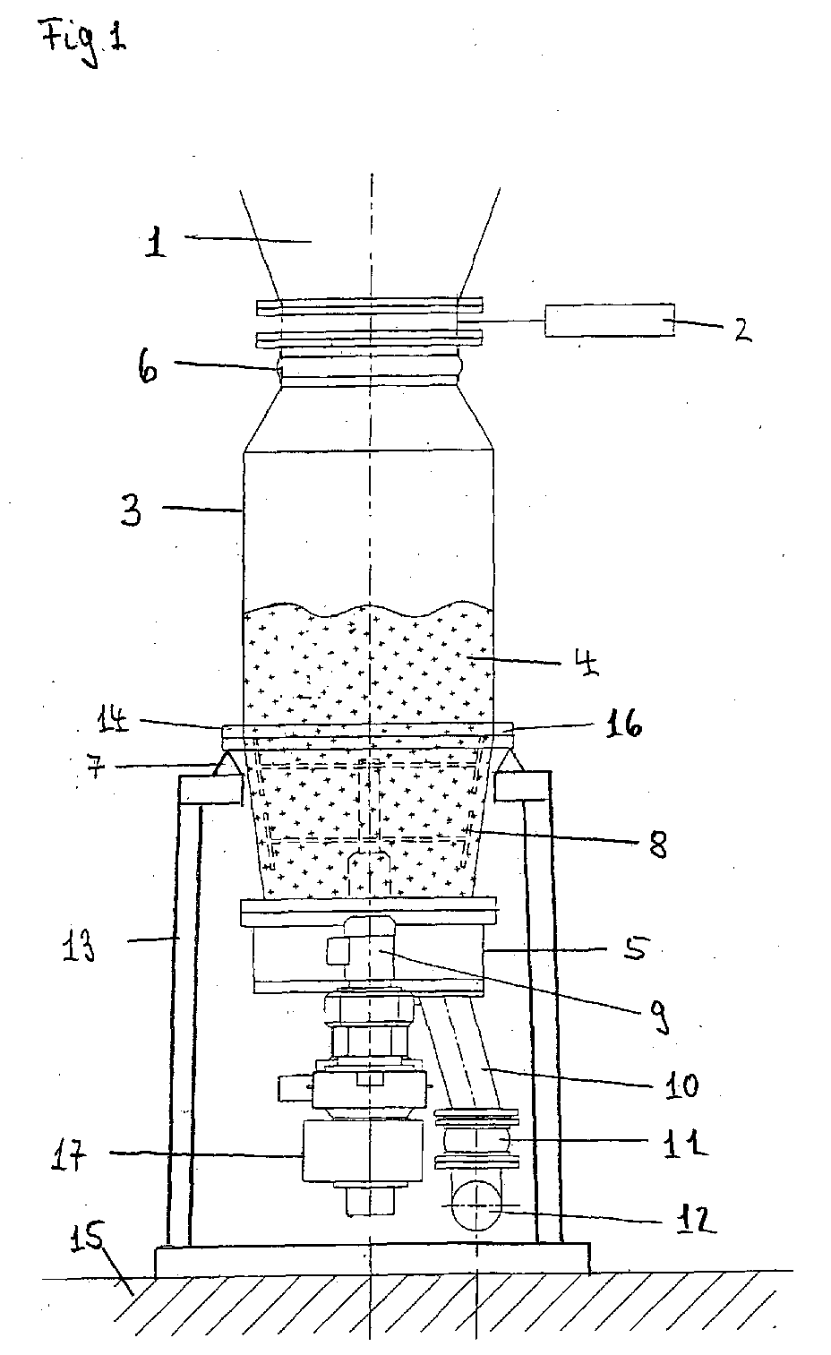
- Fig. 1:
- eine förderdruckgeregelte Kohlenstaubdosiervorrichtung mit Kontrollbehälter und einer Dosierzellenradschleuse;
- Fig. 2:
- eine schematische Darstellung der förderdruckgeregelten Kohlenstaubdosiervorrichtung mit einem Blockschaltbild der Kontrollmeßeinrichtung;
- Fig. 3:
- eine gravimetrisch geregelte Kohlenstaubdosiervorrichtung mit einer Austrags- und einer verwogenen Dosierzellenradschleuse, und
- Fig. 4:
- eine schematische Darstellung der gravimetrisch geregelten Kohlenstaubdosiervorrichtung mit einem Blockschaltbild der Kontrollmeßeinrichtung.
- Fig. 1:
- a delivery pressure controlled Pulverstaubdosiervorrichtung with control container and a Dosierzellenradschleuse;
- Fig. 2:
- a schematic representation of the delivery pressure controlled Kohlenstaubdosiervorrichtung with a block diagram of the Kontrollmeßeinrichtung;
- 3:
- a gravimetrically controlled Pulverstaubdosiervorrichtung with a discharge and a weighed Dosierzellenradschleuse, and
- 4:
- a schematic representation of the gravimetrically controlled Kohlenstaubdosiervorrichtung with a block diagram of the Kontrollmeßeinrichtung.
In Fig. 1 der Zeichnung ist eine Vorrichtung zum Dosieren von
Kohlenstaub in eine pneumatischen Förderleitung 12 dargestellt,
die im wesentlichen aus einem verwogenen Kontrollbehälter
3 und einer druckgeregelten Austragszellenradschleuse 5
besteht, die durch einen Druckaufnehmer P3 in der Förderleitung
12 geregelt wird und deren Förderstärke durch eine Kontrollmeßeinrichtung
in vorgegebenen zeitlichen Abständen nachkalibrierbar
ist.In Fig. 1 of the drawing is a device for dosing
Coal dust shown in a pneumatic conveying
Als zu dosierendes Schüttgut 4 ist Kohlenstaub vorgesehen, der
zur Verbrennung über eine pneumatische Förderleitung 12 in einen
nicht dargestellten Drehrohrofen eingeblasen wird. Um eine
konstante möglichst rückstandsfreie Verbrennung zu gewährleisten,
muß eine vorgegebene Kohlenstaubmenge mit möglichst konstanter
Förderstärke in die Förderleitung 12 dosiert eingebracht
werden. Dazu ist in einem Vorsilo 1 eine vorgegebene
Vorratsmenge von Kohlenstaub gespeichert, die kontinuierlich
oder in gewissen Zeitabständen aufgefüllt wird. Das Vorsilo 1
ist oberhalb der übrigen Dosiervorrichtung ortsfest angeordnet
und stützt sich nicht auf die übrige Dosiervorrichtung ab. Das
Vorsilo 1 ist vorzugsweise mit einem konischen Auslauf versehen,
das über eine runde Ausgabeöffnung verfügt, an der ein
Absperrmittel in Form eines elektrisch gesteuerten Absperrschiebers
2 befestigt ist. Mit diesem Absperrschieber 2 ist
das Vorsilo 1 luftdicht gegenüber dem darunterliegenden Kontrollbehälter
3 verschließbar, um den kontinuierlichen Schüttgutstrom
aus dem Vorsilo 1 zu unterbrechen. Zwischen dem Vorsilo
1 und dem Kontrollbehälter 3 ist eine bewegliche Gummimanschette
6 als kraftnebenschlußfreie Verbindung angeordnet.As to be metered
Bei einer Kohlenstaubdosiervorrichtung für eine Förderstärke
von beispielsweise 20 t/h ist vorzugsweise ein zylindrisch
ausgebildeter Kontrollbehälter 3 vorgesehen, der eine vertikale
Höhe von ca. 2 m aufweist. Der Kontrollbehälter 3 hat eine
Einlaßöffnung von ca. 700 mm Innendurchmesser bei einem Außendurchmesser
des Kontrollbehälters von ca. 1.000 mm. Im unteren
Drittel des Kontrollbehälters 3 ist zusätzlich ein Rührwerk
angeordnet, das den Kohlenstaub 4 gleichmäßig in ein darunter
vorgesehenes Austragsorgan befördert, das als Austragszellenradschleuse
5 ausgebildet ist.In a coal dust dosing device for a flow rate
For example, 20 t / h is preferably a cylindrical
trained
Der Kontrollbehälter 3 stützt sich an einem Verbindungsrand 14
auf vorzugsweise drei Wägezellen 7 ab, die kraftaufnahmeseitig
auf einem ortsfesten Stützrahmen 13 aufliegen. Die Wägezellen
7 könnten auch unterhalb der gesamten Dosiervorrichtung zwischen
dem Stützrahmen 13 und der Aufstellfläche 15 angeordnet
sein, wenn dies aus konstruktiven Gründen vorteilhaft ist.
Während des kontinuierlichen Dosierbetriebs und außerhalb der
Kontrollmeßphase ist der Absperrschieber 2 ganz oder mindestens
teilweise geöffnet, so daß der Kontrollbehälter 3 stets
bis in den Vorsilobereich gefüllt ist und durch seinen dichten
Inhalt in den Kontrollbehälter 3 eintretende Schöpf- und Leckluft
weitgehend gegenüber dem Vorsilo 1 abdichtet. An seinem
Auslaufende ist der Kontrollbehälter 3 mit einer Abdeckplatte
verschlossen, die zu der darunter angeordneten Austragszellenradschleuse
5 mindestens eine Auslauföffnung aufweist. Diese
Auslauföffnung deckt sich mit einer Einlaßöffnung der darunter
angeordneten Austragszellenradschleuse 5. Der Kontrollbehälter
3 kann unten aber auch durch die Deckplatte der Austragszellenradschleuse
5 verschlossen werden, die mit dem unteren Rand
16 des Kontrollbehälters 3 verschraubt ist. Die Austragszellenradschleuse
5 ist als horizontale Zellenradschleuse ausgebildet,
die den auszutragenden Kohlenstaub 4 von einer Einlaßöffnung
mittels eines angetriebenen Flügelrads über einen Winkelbereich
von ca. 180° zu einem Auslaßbereich befördert,
durch die der Kohlenstaub 4 nach unten in die pneumatische
Förderleitung 12 ausfällt.The
Von der Austragsöffnung der Zellenradschleuse 5 ist ein Austragsrohr
10 vorgesehen, das über einer beweglichen Rohrmanschette
11 kraftnebenschlußfrei mit der pneumatischen Förderleitung
12 verbunden ist. An der Förderleitung 12 ist ein
nicht dargestelltes Gebläse angeschlossen, das eine kontinuierliche
Luftmenge in die Förderleitung 12 einbläst, durch die
der eindosierte Kohlenstaub in den Ofen eingeblasen wird. Als
Teil der Kontrollmeßeinrichtung ist der Kontrollbehälter 3 mit
der daran befestigen Austragsschleuse 5 und dem Rührwerk 8
verwogen auf den Wägezellen 7 abgestützt.From the discharge opening of the
Die Dosierung mit einer Austragszellenradschleuse 5 kann volumetrisch
erfolgen, indem die Zellenradschleuse mit einer vorgegebenen
Drehzahl den eingeführten Kohlenstaub 4 von der Auslaßöffnung
des Kontrollbehälters 3 in das Austragsrohr 10 befördert.
Soweit dies wie vorstehend vorgesehen mit nur einer
Zellenradschleuse 5 durchgeführt wird, arbeitet diese gleichzeitig
auch als Dosierorgan. Dabei verhält sich die ausgetragene
Förderstärke weitgehend linear zur Zellenraddrehzahl, so
daß eine vorbestimmte Förderstärke von beispielsweise 20 t/h
einer vorbestimmbaren Zellenraddrehzahl entspricht. Diese kann
durch eine Steuerung des Antriebsmotors 9 der Zellenradschleuse
5 eingestellt und damit vorgegeben werden. Durch die Kontrollmeßeinrichtung
mit dem verwogenen Kontrollbehälter 3 und
einer Regelung des Antriebsmotors 9 der Austragszellenradschleuse
bzw. Dosierzellenradschleuse 5 kann die volumetrische
Dosiergenauigkeit verbessert werden.The metering with a
Eine derartige volumetrische Kohlenstaubdosierung ist für die
meisten Anwendungen allerdings nicht genau genug, da damit
kurzzeitige Dosierschwankungen nicht ausgeregelt werden können.
Deshalb ist bei der erfindungsgemäßen Kohlenstaubdosiervorrichtung
eine druckgeregelte Dosierung mit einer Nachkalibrierung
mittels der Kontrollmeßeinrichtung vorgesehen. Dazu
ist in der Förderleitung 12 zwischen dem Gebläse und der Kohlenstaubeinleitungsstelle
ein nicht dargestellter Druckaufnehmer
P3 eingebaut, der den Druck in der Förderleitung 12 erfaßt.
Eine druckgeregelte Dosierung kann durch eine Differenzdruckmessung
in einem homogenen Förderleitungsteil noch verbessert
werden, in dem möglichst wenig Förderluftturbulenzen
auftreten.Such a volumetric coal dust dosage is for the
Most applications, however, are not accurate enough with that
short-term Dosierschwankungen can not be compensated.
Therefore, in the pulverized coal metering device of the present invention
a pressure-controlled dosage with a recalibration
provided by the Kontrollmeßeinrichtung. To
is in the
Das mit der Vorrichtung nach Fig. 1 durchgeführte Dosierverfahren
zur kontinuierlichen Kohlenstaubeinblasung in einen
Ofen ist in Fig. 2 der Zeichnung schematisch dargestellt und
wird anhand des Blockschaltbildes näher beschrieben. Die Kohlenstaubdosiervorrichtung
besteht dabei im wesentlichen aus
einer druckabhängig geregelten Austragszellenradschleuse 5 und
einer Kontrollmeßeinrichtung. Während des geregelten Dosierbetriebs,
ohne daß dabei eine Kontrollmessung erfolgt, ist der
Absperrschieber 2 am Vorsilo 1 geöffnet und der Kontrollbehälter
3 bis oben hin mit Kohlenstaub 4 befüllt. Über das rotierende
Rührwerk 8, das über eine Antriebswelle mit einem eigenen
Antrieb 17 verbunden ist, wird der Kohlenstaub 4 über die
Auslaßöffnung des Kontrollbehälters 3 in eine Kammer der Horizontalzellenradschleuse
5 geleitet. Durch das ebenfalls rotierende
Zellenrad werden nacheinander alle Kammern gefüllt und
zu einer etwa 180° gegenüberliegenden Austragsöffnung gefördert,
so daß bei einer bestimmten Umlaufgeschwindigkeit im
Grunde immer eine bestimmte Kohlenstaubmenge pro Zeiteinheit
in die Förderleitung 12 ausgetragen wird.The metering process carried out with the device according to FIG
for continuous pulverized coal injection into one
Furnace is shown schematically in Fig. 2 of the drawing and
will be described in more detail with reference to the block diagram. The coal dust dosing device
consists essentially of
a pressure-dependent controlled
Da die Körnung, die Konsistenz, die Zusammensetzung und auch
der Feuchtigkeitsgehalt kurzzeitig schwanken können, ist eine
Regelung der Antriebsdrehzahl der Zellenradschleuse 5 zur Verbesserung
der Dosiergenauigkeit vorgesehen. Dazu ist der Antriebsmotor
9 der Austragszellenradschleuse 5 mit einem Regler
23 verbunden, dem ein Sollwert einer bestimmten Förderstärke
in t/h mittels eines Sollwertgebers 18 vorgebbar ist. Der Regelkreis
19 ist andererseits noch mit dem Druckaufnehmer P3 in
der Förderleitung 12 verbunden, der einen Druckwert bzw. Differenzdruckwert
erfaßt, der im Idealfall linear von der in der
Förderleitung 12 eingebrachten Kohlenstaubmenge abhängt. Dieser
Druckaufnehmer P3 ist mit einer Aufnehmerschaltung 20 als
elektronische Rechenschaltung verbunden, in der die lineare
Abhängigkeit zwischen dem Förderdruck und der Förderstärke
eingegeben ist und die aus dem jeweils erfaßten Förderdruck
bzw. Differenzförderdruck einen Förderstärken-Istwert (t/h)
ermittelt.Because the grain, the consistency, the composition and also
The moisture content can fluctuate for a short time is one
Control of the input speed of the
Der ideale Zusammenhang zwischen dem Druck in der Förderleitung
12 und der ausgetragenen Förderstärkenmenge wird in der
Praxis noch von Faktoren wie beispielsweise der Förderlufttemperatur,
der Druckunterschiede in der Zellenradschleuse 5 und
im Kontrollbehälter 3 und mit den damit zusammenhängende Strömungsverhältnissen
beeinflußt, so daß noch eine Kompensationsschaltung
21 als elektronische Rechenschaltung vorgesehen ist.
Durch diese Kompensationsschaltung 21 erfolgt mindestens eine
elektronische Druckkompensation, die insbesondere die Druckunterschiede
an der Austrags- bzw. Dosierzellenradschleuse 5 berücksichtigt.
Dazu ist am Auslauf der Schleuse 5 ein weiterer
Druckaufnehmer P1 und im Kontrollbehälter 3 ein zusätzlicher
Druckaufnehmer P2 vorgesehen, die mit der Kompensationsschaltung
21 verbunden sind. Dieser ist ein Rechenalgorithmus vorgegeben,
der dem Einfluß der Druckverhältnisse auf die Ist-Förderstärke
entspricht. Die Kennwerte dazu werden der Kompensationsschaltung
21 vorgegeben oder aufgrund eines Testbetriebs
ermittelt.The ideal relationship between the pressure in the
Aus der idealen förderleitungsabhängigen Ist-Förderstärke und
den jeweils erfaßten Druckwerten durch die Druckaufnehmer P1
und P2 wird in der Kompensationsschaltung 21 eine kompensierte
Ist-Förderstärke errechnet, die den Einfluß der Druckverhältnisse
an der Austragsschleuse 5 berücksichtigt und damit der
tatsächlichen Förderstärke in der pneumatischen Förderleitung
12 weitgehend entspricht. Diese wird mit der vorgegebenen
Soll-Förderstärke verglichen und bei einer Abweichung durch
den Regler 23 durch eine Drehzahländerung der Dosierzellenradschleuse
5 ausgeregelt. From the ideal delivery line dependent actual flow rate and
the respectively detected pressure values by the pressure transducer P1
and P2 is compensated in the
Eine derartige Förderstärkenregelung kann auch mit einer Mikrowellen-
oder Ultraschallerfassung in der Förderleitung 12
erfolgen. Dazu wird über eine Mikrowellen- oder Ultraschallaufnehmervorrichtung
die Verteilungsdichte von Luft und
Kohlenstaub auf einem Querschnittsabschnitt im Förderrohr 12
erfaßt und daraus in einer Aufnehmerschaltung die Ist-Förderstärke
errechnet. Diese kann dann wiederum als Führungsgröße
für den Regler 23 verwandt werden.Such a delivery rate control can also be implemented with a microwave
or ultrasonic detection in the
Zur Verbesserung der Dosiergenauigkeit schlägt die Erfindung
noch ein gravimetrisches Kontrollmeßverfahren vor, das zur
Nachkalibrierung der druckabhängigen oder verteilungsabhängigen
Förderstärkenregelung dient. Dazu ist eine Kontrollmeßeinrichtung
vorgesehen, die mindestens aus dem verwogenen Kontrollbehälter
3 mit großer Einlaßöffnung und etwa gleich großem
Durchflußquerschnitt mit anschließendem Dosierorgan und
einer elektronischen Rechenschaltung als Kontrollmeßschaltung
22 zum elektronischen Druckausgleich besteht. Dazu ist als Dosierorgan
meist eine horizontale Zellenradschleuse 5 vorgesehen,
die mit verwogen wird und über einen kleineren Auslaßquerschnitt
die Schüttgüter 4 in die Förderleitung 12 austrägt.
Dabei besteht das Problem darin, daß durch den Überdruck
in der Förderleitung 12 bei einer statischen Kontrollmessung
zusätzliche Kräfte auf die Wägezellen 7 einwirken, die
dieses Wägeergebnis verfälschen können. Deshalb schlägt die
Erfindung vor, diese druckabhängigen Krafteinwirkungen auf die
Wägezellen 7 während der Kontrollmessung rechnerisch oder mechanisch
zu kompensieren. Dazu sind ebenfalls die beiden
Druckaufnehmer P1 und P2 vorgesehen, die zum einen die Druckbelastung
an der Austrittsquerschnittsstelle durch den Aufnehmer
P1 und andererseits die Druckbelastung an der Eintrittsquerschnittsstelle
durch den Druckaufnehmer P2 vor dem Absperrschieber
2 erfassen. Wird nun zu einer Kontrollmessung
der Absperrschieber 2 geschlossen, während noch Kohlenstaub
ausgetragen wird, herrscht an der Austragsquerschnittsstelle
ein Überdruck, der etwa dem Förderdruck entspricht. Über die
Austrittsquerschnittsstelle entsteht dadurch eine Krafteinwirkung
auf die Wägezellen 7, die entgegen der Gewichtskraft
wirkt. Bei der Kontrollmessung während eines oberen Füllstandspunktes
entsteht in dem oberen entleerten Behälterbereich
ein Unterdruck, der durch den Druckaufnehmer P2 erfaßt
und der ebenfalls zu einer Kraftwirkung auf die Wägezellen 7
entgegen der Gewichtskraft wirkt.To improve the dosing accuracy, the invention proposes
a gravimetric Kontrollmeßverfahren before, the
Recalibration of the pressure-dependent or distribution-dependent
Flow rate control is used. This is a Kontrollmeßeinrichtung
provided, at least from the weighed
Das zum Zeitpunkt des oberen Füllstandspunkts ermittelte Wägeergebnis
wird deshalb um die druckabhängige Krafteinwirkung
im oberen Behälterteil und im unteren Behälterteil bzw. an der
mitverwogenen Dosierzellenradschleuse 5 rechnerisch ausgeglichen.
Dazu ist eine elektronische Rechenschaltung in Form einer
Kontrollmeßschaltung 22 als Ausgleichsmittel vorgesehen,
die sowohl mit den Wägezellen 7 als auch mit den Druckaufnehmern
P1 und P2 verbunden ist. Dabei ergeben sich zum Druckausgleich
Korrekturwerte, die in der Kontrollmeßschaltung 22 aufgrund
des ermittelten Druckes und der druckbeaufschlagten
wirksamen Querschnittsflächen errechnet werden. Mit Hilfe des
Druckaufnehmers P2 und der wirksamen Querschnittsfläche am Absperrschieber
2 sowie dem Druck am Druckaufnehmer P1 und dem
wirksamen Querschnitt des Austragsrohres 10 wird dabei die
Kraftwirkung auf die Wägezellen 7 errechnet, die zum Zeitpunkt
der ersten Kontrollwägung wirken. Um diese Werte wird die Gewichtskraft
bei der ersten Kontrollwägung korrigiert, so daß
dadurch ein sehr genaues Kontrollbehältergewicht im gefüllten
Zustand ermittelbar ist, das nicht durch die unterschiedlichen
Druckverhältnisse und die unterschiedlichen wirksamen Belastungsquerschnitte
verfälscht wird.The weighing result determined at the time of the upper filling point
is therefore the pressure-dependent force
in the upper container part and in the lower container part or at the
weighed
Zur weiteren Kontrollmessung wird nun bei geschlossenem Absperrschieber
2 nach einer bestimmten Förderzeit mindestens
noch eine weitere Kontrollmessung an einem unteren Füllstand
des Kontrollbehälters 3 durchgeführt. Während dieses Auslaufzeitraums
hat sich der Behälter 3 von Kohlenstaub entleert und
ist mit Schöpf- und Leckluft über die Zellenradschleuse 5 befüllt.
Diese jetzt im Kontrollbehälter 3 befindliche Luft erzeugt
bei der unteren Füllstandsmessung einen Überdruck am
Aufnehmer P2, der in etwa dem Förderdruck entspricht. Dies ist
allerdings nur dann gegeben, wenn der ausgetragene Kohlenstaub
durch gleiche Mengenanteile Schöpf- und Leckluft in den Kontrollbehälter
3 gelangt ist. Das Gewichtsergebnis am unteren
Füllstandspunkt wird deshalb in der Kontrollmeßschaltung 22 um
die ermittelte Krafteinwirkung auf die Wägezellen 7 rechnerisch
korrigiert.For further control measurement is now with
Aus den beiden korrigierten Gewichtswerten errechnet die Kontrollmeßschaltung
22 einen Differenzgewichtswert, der der Austragsmenge
während des Zeitraums zwischen den beiden Kontrollmeßzeitpunkten
entspricht. Die aus der Kontrollmeßzeit errechnete
tatsächliche Ist-Förderstärke wird nun mit der eingeregelten
kontinuierlichen Ist-Förderstärke in der Kompensationsschaltung
21 verglichen und um die Abweichung nachkalibriert.
Dazu wird die Differenz der statischen Förderstärkenermittlung
zu dem dynamischen Ist-Förderstärkenwert errechnet und daraus
ein Korrekturwert oder Korrekturfaktor gebildet, um den die
dynamische Ist-Förderstärke fortlaufend korrigiert wird. Dieser
korrigierte Ist-Förderstärkenwert wird als Führungsgröße
für den Regelkreis 19 verwendet und über den vorgegebenen
Sollwert ausgeregelt. Eine derartige Kontrollmessung erfolgt
vorzugsweise in einem Meßzeitraum von etwa einer Minute sowie
einer statischen Kontrollmenge von ca. 300 kg und kann in vorgegebenen
Zeitabständen oder aufgrund anderer Kriterien beliebig
wiederholt werden. Eine derartige Kontrollmeßeinrichtung
kann nicht nur bei Zellenradschleusen 5 als Dosierorgan eingesetzt
werden, sondern auch beispielsweise bei Förderschnecken
oder anderen druckbelastbaren Förderorganen. The control measuring circuit calculates from the two corrected weight values
22, a difference weight value, that of the discharge amount
during the period between the two control times
equivalent. The calculated from the Kontrollmeßzeit
Actual actual delivery will now be adjusted
continuous actual flow rate in the
Bei einer bevorzugten Ausführung der Kontrollmeßvorrichtung
ist vorgesehen, während der Kontrollmeßzeit den Kontrollbehälter
3 mit Förderdruck zu beaufschlagen. Dazu sind noch zusätzliche
ventilgesteuerte Druckluftleitungen als Druckausgleichsvorrichtung
notwendig, die dem Kontrollbehälter 3 nach dem
Schließen des Absperrschiebers 2 mindestens soviel Förderluft
zuleiten, wie Kohlenstaub gleichzeitig ausgetragen wird. Dadurch
herrscht während der Kontrollmeßzeit in der Dosiervorrichtung
vom Kontrollbehälter 3 bis zur Förderleitung 12 kein
Druckunterschied, so daß lediglich über den Einlaßquerschnitt
des Kontrollbehälters 3 eine Korrektur der statischen Wägeergebnisse
vorgenommen werden muß. Da dieser Förderdruck und die
druckbeaufschlagte wirksame Querschnittsfläche bekannt ist,
kann dies über einen vorgebbaren Faktor in der Kontrollmeßschaltung
22 als Ausgleichsmittel berücksichtigt werden. Dies
hat zusätzlich den Vorteil, daß durch den leerlaufenden Kontrollbehälter
3 während der Kontrollmeßzeit nicht mehr Schöpfund
Leckluft in den Kontrollbehälter einströmt als während des
übrigen Dosierbetriebs, so daß die Dosierkonstanz gleichbleibend
ist.In a preferred embodiment of the Kontrollmeßvorrichtung
is provided during the Kontrollmeßzeit the
Eine derartige Dosiervorrichtung mit einer Dosierzellenradschleuse
5 ist durch den stets gefüllten Kontrollbehälter 3
auch ohne zusätzliche Druckentkopplung zur Förderleitung mit
einem relativ hohen Förderdruck bis etwa 0,6 bar betreibbar.
Dies ist hauptsächlich dadurch möglich, daß der stets gefüllte
Kontrollbehälter 3 eine hohe Abdichtwirkung gegenüber dem Atmosphärendruck
im Vorsilo 1 aufweist, so daß die Dosierkonstanz
auch bei verhältnismäßig hohen Förderdrücken gewährleistet
bleibt, da wenig Leckluft den Dosieraustrag beeinträchtigt.Such a metering device with a
In Fig. 3 der Zeichnung ist ein verbessertes Ausführungsbeispiel
einer Kohlenstaubdosiervorrichtung mit zwei Zellenradschleusen
5, 25 dargestellt, das vorzugsweise bei Förderleitungsdrücken
größer 0,6 bar eingesetzt wird.In Fig. 3 of the drawing is an improved embodiment
a Kohlenstaubdosiervorrichtung with two
Die Dosiervorrichtung besteht im wesentlichen aus dem Vorsilo
1 mit Absperrschieber 2, an dem über eine bewegliche Gummimanschette
6 der Kontrollbehälter 3 mit der horizontalen Austragszellenradschleuse
5 wie schon nach Fig. 1 der Zeichnung
vorgesehen ist. Dabei werden für die gleichen Funktionselemente
die selben Bezugszeichen wie in Fig. 1 verwandt. Allerdings
ist das Füllrohr 24 zwischen der oberen Austragszellenradschleuse
5 und der unteren Dosierzellenradschleuse 25 ebenfalls
kraftnebenschlußfrei über eine bewegliche Rohrmanschette
11 mit der Dosierzellenradschleuse 25 verbunden. Diese als Dosierorgan
fungierende Dosierzellenradschleuse 25 ist auf mindestens
zwei Wägezellen 7 gelagert und über ein kraftnebenschlußfreies
Austragsrohr 10 an die pneumatische Förderleitung
12 angeschlossen. Dabei dient die Dosierzellenradschleuse 25
als gravimetrisches Dosierorgan, das im sogenannten Blockbetrieb
mit der Austragszellenradschleuse 5 betrieben wird.
Hierzu wird die Antriebsdrehzahl der Austragszellenradschleuse
5 so geregelt, daß die Beladung der verwogenen Dosierzellenradschleuse
25 konstant bleibt, wobei die Austragszellenradschleuse
5 nicht im Überlaufbetrieb fördert. Dies wird im
Grunde dadurch erreicht, daß das Füllrohr 24 bis zu einem vorgegebenen
Füllstand in etwa konstant befüllt bleibt. Die gesamte
Dosiervorrichtung mit dem Kontrollbehälter 3, der Austragszellenradschleuse
5, der Dosierzellenradschleuse 25 und
den Verbindungsrohren 10, 24 ist bis auf die Förderleitungsteile
12 an einen gemeinsamen Rahmen 13 befestigt, der insgesamt
auf vorzugsweise vier Wägezellen 7 gelagert ist, die im
wesentlichen die statische Behälterverwiegung für die Kontrollmessung
vornehmen.The metering device consists essentially of the
Durch die Dosierzellenradschleuse 25 wird eine druckmäßige
Entkopplung des Vorsilos 1 von der Förderdruckleitung 12 erreicht,
so daß diese Dosiervorrichtung bis zu einem Förderdruck
von ca. 1,2 bar mit der notwendigen Dosierkonstanz betrieben
werden kann, so daß damit auch höhere Förderstärken
bei gleicher Gebläseleistung und gleichem Förderleitungsquerschnitt
oder längeren Förderleitungen möglich sind.By
Das mit der Dosiervorrichtung nach Fig. 3 durchgeführte Verfahren
und die Nachkalibrierung mittels der Kontrollmeßeinrichtung
ist aus der schematischen Darstellung und dem Blockschaltbild
in Fig. 4 der Zeichnung ersichtlich. Im normalen
kontinuierlichen Dosierbetrieb ohne Kontrollmessung fördert
dabei die Austragszellenradschleuse 5 stets soviel Kohlenstaub
4 in das Füllrohr 24, daß die Einfüllkammern der Dosierzellenradschleuse
25 stets vollständig gefüllt werden können. Dies
wird im Blockbetrieb im wesentlichen dadurch erreicht, daß es
sich um die gleichen horizontalen Zellenradschleusen handelt,
die im wesentlichen mit der gleichen Zellenraddrehzahl arbeiten.The method performed with the metering device according to FIG. 3
and the recalibration using the Kontrollmeßeinrichtung
is from the schematic and the block diagram
in Fig. 4 of the drawing can be seen. In the normal
continuous dosing operation without control measurement promotes
while the
Durch die Wägezellen 7 unter der Dosierzellenradschleuse 25
wird deren Gewicht mit den befüllten Kammern erfaßt und in einer
elektronischen Rechenschaltung, die als Meßschaltung 26
ausgebildet ist, unter Berücksichtigung des Taragewichts deren
Füllmenge Q gewichtsmäßig ermittelt. Der Gewichtswert der
Füllmenge Q wird der Kompensationsschaltung 21 übermittelt, in
der die Druckverhältnisse an der Dosierzellenradschleuse 25
berücksichtigt werden. Denn durch die hohe Druckbelastung an
der Dosierschleuse 25 kann es vorkommen, daß nicht die gesamte
Füllmenge bei gleicher Umdrehung vollständig in die Förderleitung
12 abgegeben wird, so daß dadurch ein Meßfehler in der
gravimetrischen Dosierung auftritt. Dies wird bei einer hohen
Druckbelastung in der Kompensationsschaltung 21 elektronisch
bzw. rechnerisch kompensiert. Dazu wird durch die Druckaufnehmer
P1 und P2 der Druck am Eingang (Füllrohr) und Ausgang
(Austragsrohr) der Dosierzellenradschleuse 25 erfaßt und der
Kompensationsschaltung 21 zugeführt. Bei einem hohen Differenzdruck
zwischen den Druckaufnehmern P1 und P2 wird dies
entsprechend berücksichtigt. Dazu ist in der Kompensationsschaltung
21 eine aufgenommene Kennlinie eingegeben oder eine
entsprechende digitale Wertetabelle gespeichert, die diesen
Fehler in der Austragsförderstärke in Abhängigkeit eines zunehmenden
Differenzdrucks angibt. Durch einen Korrekturwert in
Abhängigkeit des Differenzdrucks wird dies in der Kompensationsschaltung
21 berücksichtigt und daraus eine korrigierte
Füllmenge Q1 errechnet.Through the
In einer nachfolgenden elektronischen Rechenschaltung, die als
Istwertschaltung 27 ausgebildet ist, wird daraus unter Berücksichtigung
der von einem Tachogenerator 28 gelieferten Drehzahl
oder Umfangsgeschwindigkeit V ein korrigierter Ist-Förderstärkenwert
gebildet. Diese Ist-Förderstärke wird einem
Regelkreis 19 zugeführt, die diesen mit einem vorgegebenen
Sollwert eines Sollwertgebers 18 vergleicht und daraus eine
Regelgröße errechnet, mit der der Regler 23 die Antriebsdrehzahl
der Dosierzellenradschleuse 25 entsprechend der vorgegebenen
Sollförderstärke ausregelt.In a subsequent electronic calculation circuit, the
Da auch diese gravimetrische kontinuierliche Förderstärkenmessung
und -regelung durch dynamische Störungen mit Meßfehlern
behaftet sein kann, ist auch bei dieser Dosiervorrichtung mit
zwei Zellenradschleusen 5, 25 eine Kontrollmeßschaltung 22
vorgesehen. Durch diese wird in vorgegebenen Zeitabständen eine
statische Kontrollwägung durchgeführt, um eine Nachkalibrierung
der gravimetrischen Förderstärkenermittlung vorzunehmen.
Dazu werden wieder mindestens zwei statische Gewichtswerte
zwischen zwei verschiedenen Füllständen durch die Wägezellen
7 unter der Dosiervorrichtung erfaßt. Zunächst wird dazu
der Kontrollbehälter 3 durch den Absperrschieber 2 luftdicht
verschlossen und der Behälter mit dem Förderleitungsdruck am
Druckaufnehmer P2 beaufschlagt. Da nun zwischen den verwogenen
Teilen kein Differenzdruck besteht, wirken auf die Wägezellen
7 unter der Dosiervorrichtung während der statischen Kontrollmessung
nur zusätzliche druckabhängige statische Kräfte, die
aus der Differenz der wirksamen Querschnittsflächen A1 am Absperrschieber
2 und dem Querschnitt A2 des Austragsrohres 10
resultieren und die das statische Gewichtsergebnis beeinflussen.
Deshalb werden in der Kontrollmeßschaltung 22 die wirksamen
druckbeaufschlagten Querschnittsflächen A1 und A2 und die
Wägezellensignale WZ der Kontrollwägungen eingegeben.As well as this gravimetric continuous flow rate measurement
and control by dynamic disturbances with measurement errors
may be associated with, is also in this metering device
two
Aus der Kontrollwägung für den oberen Füllstand errechnet die
Kontrollmeßschaltung 22 einen statischen Gewichtswert, der um
die Krafteinwirkung durch den Förderdruck korrigiert ist. Eine
derartige Gewichtsermittlung erfolgt ebenfalls für den unteren
Füllstandswert. Aus den beiden korrigierten statischen Gewichtswerten
und dem Entleerungszeitraum zwischen der Gewichtswerterfassung
errechnet die Kontrollmeßschaltung 22 einen
Förderstärkenwert. Dieser statische Förderstärkenkontrollwert
wird der Istwertschaltung zugeführt und dort mit dem kontinuierlichen
Förderstärkenistwert verglichen und bei einer
Abweichung ein weiterer Korrekturfaktor oder -wert ermittelt,
um den die zukünftigen kontinuierlichen Istwertergebnisse zusätzlich
korrigiert und wie vorstehend beschrieben ausgeregelt
werden.The checkweighing for the upper level calculates the
Kontrollmeßschaltung 22 a static weight value, the order
the force effect is corrected by the delivery pressure. A
Such weight determination also takes place for the lower one
Level value. From the two corrected static weight values
and the discharge period between the weight value detection
the
Eine derartige Kontrollmessung bedarf etwa einer Kontrollzeit
von einer Minute, in der ca. eine Kontrollmenge von 300 kg
Kohlenstaub aus dem Kontrollbehälter 3 ausgetragen werden. Eine
derartige Kontrollmessung kann in beliebigen Zeitabständen
oder aufgrund anderer Anlässe zur Verbesserung der Dosiergenauigkeit
wiederholt werden. Da durch die Wiederauffüllung des
Kontrollbehälters 3 die gravimetrische Dosierung mit der Dosierzellenradschleuse
25 nicht beeinflußt werden kann, wird
die kontinuierliche gravimetrische Dosierung durch die statischen
Kontrollwägungen nicht beeinträchtigt. Such a control measurement requires about a control time
of a minute, in which about a control amount of 300 kg
Carbon dust be discharged from the
Das Kontrollmeßverfahren kann auch bei einer förderdruckgesteuerten
Dosierregelung der Dosierzellenradschleuse 25 eingesetzt
werden. Desweiteren ist die Kontrollmeßeinrichtung auch
einsetzbar, wenn statt der Dosierzellenradschleuse 25 ein Coriolis-Durchflußmesser,
eine Schneckendosiervorrichtung oder
andere gravimetrische Durchflußmeßvorrichtungen vorgesehen
sind. Bei hohen Genauigkeitsanforderungen und hohen Förderdrücken
können auch zwei Zellenradschleusen 5, 25 zur Druckentkopplung
mit einer gravimetrischen zusätzlichen Durchflußmeßeinrichtung
kombiniert werden.The Kontrollmeßverfahren can also with a delivery pressure controlled
Dosierregelung the
Ist hingegen eine Kontrollmeßeinrichtung aus Genauigkeitsgründen-nicht
unbedingt notwendig, so kann eine Förderdruckentkopplung
auch durch Verwendung von zwei Zellenradschleusen 5,
25 vorgesehen werden, wobei die Dosiergenauigkeit durch eine
förderdruckgeregelte Dosierzellenradschleuse 25 verbesserbar
ist. Dabei kann die Dosierkonstanz zusätzlich noch durch eine
elektronische Druckkompensation an der Dosierzellenradschleuse
erhöht werden. Die einzelnen Schaltungsteile der Aufnehmer -
20, Kompensations- 21, Meß- 26, Istwert- 27 und Kontrollmeßschaltung
22 können auch in einer gemeinsamen elektronischen
digitalen Schaltung integriert sein, dessen Meß- und Rechenschritte
programmgesteuert sind.If, however, a Kontrollmeßeinrichtung for accuracy reasons-not
absolutely necessary, so can a delivery pressure decoupling
also by using two
Claims (15)
Priority Applications (1)
| Application Number | Priority Date | Filing Date | Title |
|---|---|---|---|
| PL04008550T PL1467190T3 (en) | 2003-04-11 | 2004-04-08 | Device for continuous dosing and for pneumatically conveying of free-flowing products. |
Applications Claiming Priority (2)
| Application Number | Priority Date | Filing Date | Title |
|---|---|---|---|
| DE10317001A DE10317001B3 (en) | 2003-04-11 | 2003-04-11 | Device for continuous dosing and pneumatic conveying of free-flowing goods |
| DE10317001 | 2003-04-11 |
Publications (3)
| Publication Number | Publication Date |
|---|---|
| EP1467190A2 true EP1467190A2 (en) | 2004-10-13 |
| EP1467190A3 EP1467190A3 (en) | 2006-07-05 |
| EP1467190B1 EP1467190B1 (en) | 2009-06-10 |
Family
ID=32864479
Family Applications (1)
| Application Number | Title | Priority Date | Filing Date |
|---|---|---|---|
| EP04008550A Expired - Lifetime EP1467190B1 (en) | 2003-04-11 | 2004-04-08 | Device for continuous dosing and for pneumatically conveying of free-flowing products. |
Country Status (7)
| Country | Link |
|---|---|
| EP (1) | EP1467190B1 (en) |
| AT (1) | ATE433565T1 (en) |
| DE (2) | DE10317001B3 (en) |
| DK (1) | DK1467190T3 (en) |
| ES (1) | ES2324661T3 (en) |
| PL (1) | PL1467190T3 (en) |
| PT (1) | PT1467190E (en) |
Cited By (9)
| Publication number | Priority date | Publication date | Assignee | Title |
|---|---|---|---|---|
| EP3228998A1 (en) * | 2016-03-23 | 2017-10-11 | Ronald Jürgen Hoffer | Quasi-static pressure compensation and correction of the weighing method in discontinuously working asphalt mixing plants |
| CN107826278A (en) * | 2017-12-11 | 2018-03-23 | 洛阳乐森石化新材料有限公司 | A kind of material automatic metering equipment |
| CN107966195A (en) * | 2017-11-07 | 2018-04-27 | 常州宏大智能装备产业发展研究院有限公司 | The weighing method and weighing device of powder material |
| CN110371675A (en) * | 2019-08-15 | 2019-10-25 | 北京建筑材料科学研究总院有限公司 | Intelligent skewed slot turns to sub-material control system and its control method |
| CN112010060A (en) * | 2020-09-01 | 2020-12-01 | 山东研维自动化科技有限公司 | Powder material metering and loading device |
| US11193813B2 (en) * | 2016-07-27 | 2021-12-07 | Bühler AG | Dosing and weighing device and method for determining the weight of a product in a dosing and weighing device |
| CN113847976A (en) * | 2021-10-28 | 2021-12-28 | 王冬冬 | A measuring device for measuring the weight and moisture content of separated crops |
| CN114393748A (en) * | 2022-01-18 | 2022-04-26 | 浙江晨浩智能科技有限公司 | Fault-tolerant calculation control method for on-line weighing of large-scale raw material station |
| CN116145500A (en) * | 2023-03-31 | 2023-05-23 | 徐州徐工养护机械有限公司 | Compensation system for rapidly balancing negative pressure |
Families Citing this family (3)
| Publication number | Priority date | Publication date | Assignee | Title |
|---|---|---|---|---|
| FI127395B2 (en) | 2016-08-15 | 2024-04-12 | Jauhetekniikka Oy Kotka | Dosing equipment and method for dosing powder and/or granular matter |
| DE102016119596A1 (en) * | 2016-10-14 | 2018-04-19 | Plast-Control Gmbh | Method for filling a weighing container for plastic granules |
| CN114620490A (en) * | 2022-02-22 | 2022-06-14 | 中国电建集团西北勘测设计研究院有限公司 | Dust removal system and method for sand and gravel aggregate processing by low-pressure pneumatic continuous conveying pump |
Family Cites Families (6)
| Publication number | Priority date | Publication date | Assignee | Title |
|---|---|---|---|---|
| DE3217406C2 (en) * | 1982-05-08 | 1986-06-05 | Pfister Gmbh, 8900 Augsburg | Device for continuous gravimetric dosing of loose material |
| DE4332030A1 (en) * | 1993-09-21 | 1995-03-23 | Pfister Gmbh | Method and device for gravimetric dosing of bulk materials |
| DE4443053A1 (en) * | 1994-12-05 | 1996-06-13 | Pfister Gmbh | Method and device for continuous, gravimetric metering and mass flow determination of flowable goods |
| DE19739712B4 (en) * | 1997-09-10 | 2009-04-16 | Pfister Gmbh | Method and device for continuous, gravimetric dosing |
| DE19749873A1 (en) * | 1997-11-11 | 1999-05-12 | Pfister Gmbh | Method and device for continuous dosing |
| DE10106798A1 (en) * | 2001-02-10 | 2002-08-14 | Pfister Gmbh | metering |
-
2003
- 2003-04-11 DE DE10317001A patent/DE10317001B3/en not_active Expired - Fee Related
-
2004
- 2004-04-08 EP EP04008550A patent/EP1467190B1/en not_active Expired - Lifetime
- 2004-04-08 ES ES04008550T patent/ES2324661T3/en not_active Expired - Lifetime
- 2004-04-08 PL PL04008550T patent/PL1467190T3/en unknown
- 2004-04-08 AT AT04008550T patent/ATE433565T1/en active
- 2004-04-08 PT PT04008550T patent/PT1467190E/en unknown
- 2004-04-08 DK DK04008550T patent/DK1467190T3/en active
- 2004-04-08 DE DE502004009585T patent/DE502004009585D1/en not_active Expired - Lifetime
Cited By (12)
| Publication number | Priority date | Publication date | Assignee | Title |
|---|---|---|---|---|
| EP3228998A1 (en) * | 2016-03-23 | 2017-10-11 | Ronald Jürgen Hoffer | Quasi-static pressure compensation and correction of the weighing method in discontinuously working asphalt mixing plants |
| US11193813B2 (en) * | 2016-07-27 | 2021-12-07 | Bühler AG | Dosing and weighing device and method for determining the weight of a product in a dosing and weighing device |
| CN107966195A (en) * | 2017-11-07 | 2018-04-27 | 常州宏大智能装备产业发展研究院有限公司 | The weighing method and weighing device of powder material |
| CN107966195B (en) * | 2017-11-07 | 2024-03-12 | 常州宏大智能装备产业发展研究院有限公司 | Weighing method and weighing device for powder material |
| CN107826278A (en) * | 2017-12-11 | 2018-03-23 | 洛阳乐森石化新材料有限公司 | A kind of material automatic metering equipment |
| CN110371675A (en) * | 2019-08-15 | 2019-10-25 | 北京建筑材料科学研究总院有限公司 | Intelligent skewed slot turns to sub-material control system and its control method |
| CN110371675B (en) * | 2019-08-15 | 2024-03-22 | 北京建筑材料科学研究总院有限公司 | Intelligent chute steering and material distribution control system and its control method |
| CN112010060A (en) * | 2020-09-01 | 2020-12-01 | 山东研维自动化科技有限公司 | Powder material metering and loading device |
| CN113847976A (en) * | 2021-10-28 | 2021-12-28 | 王冬冬 | A measuring device for measuring the weight and moisture content of separated crops |
| CN114393748A (en) * | 2022-01-18 | 2022-04-26 | 浙江晨浩智能科技有限公司 | Fault-tolerant calculation control method for on-line weighing of large-scale raw material station |
| CN114393748B (en) * | 2022-01-18 | 2023-08-11 | 浙江晨浩智能科技有限公司 | A fault-tolerant calculation control method for online weighing of large raw material stations |
| CN116145500A (en) * | 2023-03-31 | 2023-05-23 | 徐州徐工养护机械有限公司 | Compensation system for rapidly balancing negative pressure |
Also Published As
| Publication number | Publication date |
|---|---|
| DK1467190T3 (en) | 2009-10-19 |
| DE502004009585D1 (en) | 2009-07-23 |
| ATE433565T1 (en) | 2009-06-15 |
| PT1467190E (en) | 2009-08-17 |
| ES2324661T3 (en) | 2009-08-12 |
| DE10317001B3 (en) | 2004-11-25 |
| EP1467190A3 (en) | 2006-07-05 |
| EP1467190B1 (en) | 2009-06-10 |
| PL1467190T3 (en) | 2009-10-30 |
Similar Documents
| Publication | Publication Date | Title |
|---|---|---|
| EP1444490B1 (en) | Method and device for gravimetric dosing bulk material | |
| EP0644406B1 (en) | Gravimetric dosage of bulk materials with measurement only from a limit pressure | |
| DE69409712T2 (en) | Differential dosing scale with measurement of bulk density by level determination | |
| DE10317001B3 (en) | Device for continuous dosing and pneumatic conveying of free-flowing goods | |
| EP0235562B1 (en) | Process and device for the measured supply of fine solid particles to an industrial furnace | |
| DE102011122268B3 (en) | Method and device for dosing a fluid medium | |
| DE102013000840B3 (en) | Gravimetric dosing system for coarse and fine dosage of bulk material components e.g. chemical raw materials, has closure element that is lifted to open cover and material component in discharging device is gravimetrically dosed | |
| EP3847426B1 (en) | Method for the gravimetric control of a metering device for bulk material during the refilling of its storage container, and metering device for carrying out the method | |
| DE102011101045A1 (en) | Packing machine and method for filling open bags | |
| EP0204936A2 (en) | Device for gravimetrically dosing products capable of flowing | |
| DE60106025T2 (en) | DOSING | |
| EP0796423B1 (en) | Process and device for the continual gravimetric metered dispensing and mass flow rate determination of free-flowing materials | |
| EP1883590B1 (en) | Bulk material container | |
| DE19739712B4 (en) | Method and device for continuous, gravimetric dosing | |
| EP0471234B1 (en) | Gravimetric dosing device for bulk materials | |
| EP1031014B1 (en) | Method and device for continuous dosing | |
| EP2375226A1 (en) | Device for gravimetric metering of bulk goods | |
| DE3320477C2 (en) | ||
| DE29515725U1 (en) | Device for batch dosing of starting substances into a mixer on a plastic processing machine | |
| DE8316568U1 (en) | DOSING DEVICE FOR DUST-SHAPED GOODS | |
| DE10103854A1 (en) | Measuring device for detecting a continuous mass flow rate of free-flowing goods e.g. pourable bulk materials, feeds the mass flow through a cord-like feeder channel sloping downwards and supported on a weighing cell | |
| DE3811880C2 (en) | ||
| DE1549291A1 (en) | Device for determining the conveying capacity of deduction devices | |
| DE102008062838B4 (en) | Device for continuous, gravimetric dosing of bulk solids | |
| DE20109074U1 (en) | Device for the continuous measurement and control of the mass flow |
Legal Events
| Date | Code | Title | Description |
|---|---|---|---|
| PUAI | Public reference made under article 153(3) epc to a published international application that has entered the european phase |
Free format text: ORIGINAL CODE: 0009012 |
|
| AK | Designated contracting states |
Kind code of ref document: A2 Designated state(s): AT BE BG CH CY CZ DE DK EE ES FI FR GB GR HU IE IT LI LU MC NL PL PT RO SE SI SK TR |
|
| AX | Request for extension of the european patent |
Extension state: AL HR LT LV MK |
|
| PUAL | Search report despatched |
Free format text: ORIGINAL CODE: 0009013 |
|
| AK | Designated contracting states |
Kind code of ref document: A3 Designated state(s): AT BE BG CH CY CZ DE DK EE ES FI FR GB GR HU IE IT LI LU MC NL PL PT RO SE SI SK TR |
|
| AX | Request for extension of the european patent |
Extension state: AL HR LT LV MK |
|
| 17P | Request for examination filed |
Effective date: 20061129 |
|
| AKX | Designation fees paid |
Designated state(s): AT BE BG CH CY CZ DE DK EE ES FI FR GB GR HU IE IT LI LU MC NL PL PT RO SE SI SK TR |
|
| 17Q | First examination report despatched |
Effective date: 20070319 |
|
| GRAP | Despatch of communication of intention to grant a patent |
Free format text: ORIGINAL CODE: EPIDOSNIGR1 |
|
| GRAS | Grant fee paid |
Free format text: ORIGINAL CODE: EPIDOSNIGR3 |
|
| GRAA | (expected) grant |
Free format text: ORIGINAL CODE: 0009210 |
|
| AK | Designated contracting states |
Kind code of ref document: B1 Designated state(s): AT BE BG CH CY CZ DE DK EE ES FI FR GB GR HU IE IT LI LU MC NL PL PT RO SE SI SK TR |
|
| REG | Reference to a national code |
Ref country code: GB Ref legal event code: FG4D Free format text: NOT ENGLISH |
|
| REG | Reference to a national code |
Ref country code: CH Ref legal event code: EP |
|
| REG | Reference to a national code |
Ref country code: IE Ref legal event code: FG4D Free format text: LANGUAGE OF EP DOCUMENT: GERMAN |
|
| REF | Corresponds to: |
Ref document number: 502004009585 Country of ref document: DE Date of ref document: 20090723 Kind code of ref document: P |
|
| REG | Reference to a national code |
Ref country code: ES Ref legal event code: FG2A Ref document number: 2324661 Country of ref document: ES Kind code of ref document: T3 |
|
| REG | Reference to a national code |
Ref country code: CH Ref legal event code: NV Representative=s name: TROESCH SCHEIDEGGER WERNER AG |
|
| REG | Reference to a national code |
Ref country code: PT Ref legal event code: SC4A Free format text: AVAILABILITY OF NATIONAL TRANSLATION Effective date: 20090810 |
|
| REG | Reference to a national code |
Ref country code: RO Ref legal event code: EPE |
|
| REG | Reference to a national code |
Ref country code: DK Ref legal event code: T3 |
|
| PG25 | Lapsed in a contracting state [announced via postgrant information from national office to epo] |
Ref country code: FI Free format text: LAPSE BECAUSE OF FAILURE TO SUBMIT A TRANSLATION OF THE DESCRIPTION OR TO PAY THE FEE WITHIN THE PRESCRIBED TIME-LIMIT Effective date: 20090610 |
|
| REG | Reference to a national code |
Ref country code: PL Ref legal event code: T3 |
|
| PG25 | Lapsed in a contracting state [announced via postgrant information from national office to epo] |
Ref country code: SI Free format text: LAPSE BECAUSE OF FAILURE TO SUBMIT A TRANSLATION OF THE DESCRIPTION OR TO PAY THE FEE WITHIN THE PRESCRIBED TIME-LIMIT Effective date: 20090610 Ref country code: SE Free format text: LAPSE BECAUSE OF FAILURE TO SUBMIT A TRANSLATION OF THE DESCRIPTION OR TO PAY THE FEE WITHIN THE PRESCRIBED TIME-LIMIT Effective date: 20090910 |
|
| REG | Reference to a national code |
Ref country code: IE Ref legal event code: FD4D |
|
| PG25 | Lapsed in a contracting state [announced via postgrant information from national office to epo] |
Ref country code: IE Free format text: LAPSE BECAUSE OF FAILURE TO SUBMIT A TRANSLATION OF THE DESCRIPTION OR TO PAY THE FEE WITHIN THE PRESCRIBED TIME-LIMIT Effective date: 20090610 Ref country code: EE Free format text: LAPSE BECAUSE OF FAILURE TO SUBMIT A TRANSLATION OF THE DESCRIPTION OR TO PAY THE FEE WITHIN THE PRESCRIBED TIME-LIMIT Effective date: 20090610 |
|
| PG25 | Lapsed in a contracting state [announced via postgrant information from national office to epo] |
Ref country code: SK Free format text: LAPSE BECAUSE OF FAILURE TO SUBMIT A TRANSLATION OF THE DESCRIPTION OR TO PAY THE FEE WITHIN THE PRESCRIBED TIME-LIMIT Effective date: 20090610 |
|
| PG25 | Lapsed in a contracting state [announced via postgrant information from national office to epo] |
Ref country code: BG Free format text: LAPSE BECAUSE OF FAILURE TO SUBMIT A TRANSLATION OF THE DESCRIPTION OR TO PAY THE FEE WITHIN THE PRESCRIBED TIME-LIMIT Effective date: 20090910 |
|
| PLBE | No opposition filed within time limit |
Free format text: ORIGINAL CODE: 0009261 |
|
| STAA | Information on the status of an ep patent application or granted ep patent |
Free format text: STATUS: NO OPPOSITION FILED WITHIN TIME LIMIT |
|
| 26N | No opposition filed |
Effective date: 20100311 |
|
| REG | Reference to a national code |
Ref country code: HU Ref legal event code: AG4A Ref document number: E007280 Country of ref document: HU |
|
| PG25 | Lapsed in a contracting state [announced via postgrant information from national office to epo] |
Ref country code: GR Free format text: LAPSE BECAUSE OF FAILURE TO SUBMIT A TRANSLATION OF THE DESCRIPTION OR TO PAY THE FEE WITHIN THE PRESCRIBED TIME-LIMIT Effective date: 20090911 |
|
| BERE | Be: lapsed |
Owner name: SCHENCK PROCESS G.M.B.H. Effective date: 20100430 |
|
| PG25 | Lapsed in a contracting state [announced via postgrant information from national office to epo] |
Ref country code: MC Free format text: LAPSE BECAUSE OF NON-PAYMENT OF DUE FEES Effective date: 20100430 |
|
| PG25 | Lapsed in a contracting state [announced via postgrant information from national office to epo] |
Ref country code: BE Free format text: LAPSE BECAUSE OF NON-PAYMENT OF DUE FEES Effective date: 20100430 |
|
| PG25 | Lapsed in a contracting state [announced via postgrant information from national office to epo] |
Ref country code: CY Free format text: LAPSE BECAUSE OF FAILURE TO SUBMIT A TRANSLATION OF THE DESCRIPTION OR TO PAY THE FEE WITHIN THE PRESCRIBED TIME-LIMIT Effective date: 20090610 |
|
| PG25 | Lapsed in a contracting state [announced via postgrant information from national office to epo] |
Ref country code: LU Free format text: LAPSE BECAUSE OF NON-PAYMENT OF DUE FEES Effective date: 20100408 |
|
| PGFP | Annual fee paid to national office [announced via postgrant information from national office to epo] |
Ref country code: RO Payment date: 20140324 Year of fee payment: 11 |
|
| PGFP | Annual fee paid to national office [announced via postgrant information from national office to epo] |
Ref country code: HU Payment date: 20140422 Year of fee payment: 11 |
|
| PG25 | Lapsed in a contracting state [announced via postgrant information from national office to epo] |
Ref country code: HU Free format text: LAPSE BECAUSE OF NON-PAYMENT OF DUE FEES Effective date: 20150409 Ref country code: RO Free format text: LAPSE BECAUSE OF NON-PAYMENT OF DUE FEES Effective date: 20150408 |
|
| REG | Reference to a national code |
Ref country code: FR Ref legal event code: PLFP Year of fee payment: 13 |
|
| REG | Reference to a national code |
Ref country code: DE Ref legal event code: R082 Ref document number: 502004009585 Country of ref document: DE Ref country code: DE Ref legal event code: R081 Ref document number: 502004009585 Country of ref document: DE Owner name: SCHENCK PROCESS EUROPE GMBH, DE Free format text: FORMER OWNER: SCHENCK PROCESS GMBH, 64293 DARMSTADT, DE |
|
| REG | Reference to a national code |
Ref country code: FR Ref legal event code: PLFP Year of fee payment: 14 |
|
| PGFP | Annual fee paid to national office [announced via postgrant information from national office to epo] |
Ref country code: CZ Payment date: 20170324 Year of fee payment: 14 |
|
| PGFP | Annual fee paid to national office [announced via postgrant information from national office to epo] |
Ref country code: NL Payment date: 20170419 Year of fee payment: 14 |
|
| PGFP | Annual fee paid to national office [announced via postgrant information from national office to epo] |
Ref country code: AT Payment date: 20170420 Year of fee payment: 14 Ref country code: PT Payment date: 20170406 Year of fee payment: 14 Ref country code: IT Payment date: 20170420 Year of fee payment: 14 |
|
| REG | Reference to a national code |
Ref country code: CH Ref legal event code: PCOW Free format text: NEW ADDRESS: PALLASWIESENSTRASSE 100, 64293 DARMSTADT (DE) Ref country code: CH Ref legal event code: PFA Owner name: SCHENCK PROCESS EUROPE GMBH, DE Free format text: FORMER OWNER: SCHENCK PROCESS GMBH, DE |
|
| PG25 | Lapsed in a contracting state [announced via postgrant information from national office to epo] |
Ref country code: CZ Free format text: LAPSE BECAUSE OF NON-PAYMENT OF DUE FEES Effective date: 20180408 |
|
| REG | Reference to a national code |
Ref country code: NL Ref legal event code: MM Effective date: 20180501 |
|
| REG | Reference to a national code |
Ref country code: GB Ref legal event code: 732E Free format text: REGISTERED BETWEEN 20181115 AND 20181130 |
|
| REG | Reference to a national code |
Ref country code: AT Ref legal event code: MM01 Ref document number: 433565 Country of ref document: AT Kind code of ref document: T Effective date: 20180408 |
|
| REG | Reference to a national code |
Ref country code: ES Ref legal event code: PC2A Owner name: SCHENCK PROCESS EUROPE GMBH Effective date: 20181219 |
|
| PG25 | Lapsed in a contracting state [announced via postgrant information from national office to epo] |
Ref country code: PT Free format text: LAPSE BECAUSE OF NON-PAYMENT OF DUE FEES Effective date: 20181008 Ref country code: NL Free format text: LAPSE BECAUSE OF NON-PAYMENT OF DUE FEES Effective date: 20180501 Ref country code: AT Free format text: LAPSE BECAUSE OF NON-PAYMENT OF DUE FEES Effective date: 20180408 |
|
| REG | Reference to a national code |
Ref country code: DE Ref legal event code: R081 Ref document number: 502004009585 Country of ref document: DE Owner name: SCHENCK PROCESS EUROPE GMBH, DE Free format text: FORMER OWNER: SCHENCK PROCESS EUROPE GMBH, 64293 DARMSTADT, DE |
|
| PG25 | Lapsed in a contracting state [announced via postgrant information from national office to epo] |
Ref country code: FR Free format text: LAPSE BECAUSE OF NON-PAYMENT OF DUE FEES Effective date: 20180430 Ref country code: IT Free format text: LAPSE BECAUSE OF NON-PAYMENT OF DUE FEES Effective date: 20180408 |
|
| PGFP | Annual fee paid to national office [announced via postgrant information from national office to epo] |
Ref country code: TR Payment date: 20190329 Year of fee payment: 16 |
|
| PGFP | Annual fee paid to national office [announced via postgrant information from national office to epo] |
Ref country code: GB Payment date: 20190418 Year of fee payment: 16 |
|
| PGFP | Annual fee paid to national office [announced via postgrant information from national office to epo] |
Ref country code: PL Payment date: 20190813 Year of fee payment: 16 |
|
| GBPC | Gb: european patent ceased through non-payment of renewal fee |
Effective date: 20200408 |
|
| PG25 | Lapsed in a contracting state [announced via postgrant information from national office to epo] |
Ref country code: GB Free format text: LAPSE BECAUSE OF NON-PAYMENT OF DUE FEES Effective date: 20200408 |
|
| PGFP | Annual fee paid to national office [announced via postgrant information from national office to epo] |
Ref country code: DE Payment date: 20210420 Year of fee payment: 18 |
|
| PGFP | Annual fee paid to national office [announced via postgrant information from national office to epo] |
Ref country code: DK Payment date: 20210422 Year of fee payment: 18 Ref country code: CH Payment date: 20210420 Year of fee payment: 18 |
|
| REG | Reference to a national code |
Ref country code: ES Ref legal event code: FD2A Effective date: 20210831 |
|
| PG25 | Lapsed in a contracting state [announced via postgrant information from national office to epo] |
Ref country code: ES Free format text: LAPSE BECAUSE OF NON-PAYMENT OF DUE FEES Effective date: 20200409 |
|
| PG25 | Lapsed in a contracting state [announced via postgrant information from national office to epo] |
Ref country code: TR Free format text: LAPSE BECAUSE OF NON-PAYMENT OF DUE FEES Effective date: 20200408 |
|
| PG25 | Lapsed in a contracting state [announced via postgrant information from national office to epo] |
Ref country code: PL Free format text: LAPSE BECAUSE OF NON-PAYMENT OF DUE FEES Effective date: 20200408 |
|
| REG | Reference to a national code |
Ref country code: DE Ref legal event code: R119 Ref document number: 502004009585 Country of ref document: DE |
|
| REG | Reference to a national code |
Ref country code: DK Ref legal event code: EBP Effective date: 20220430 |
|
| REG | Reference to a national code |
Ref country code: CH Ref legal event code: PL |
|
| PG25 | Lapsed in a contracting state [announced via postgrant information from national office to epo] |
Ref country code: LI Free format text: LAPSE BECAUSE OF NON-PAYMENT OF DUE FEES Effective date: 20220430 Ref country code: DE Free format text: LAPSE BECAUSE OF NON-PAYMENT OF DUE FEES Effective date: 20221103 Ref country code: CH Free format text: LAPSE BECAUSE OF NON-PAYMENT OF DUE FEES Effective date: 20220430 |
|
| PG25 | Lapsed in a contracting state [announced via postgrant information from national office to epo] |
Ref country code: DK Free format text: LAPSE BECAUSE OF NON-PAYMENT OF DUE FEES Effective date: 20220430 |