EP1467201B1 - Analysegerät mit temperatursensor - Google Patents
Analysegerät mit temperatursensor Download PDFInfo
- Publication number
- EP1467201B1 EP1467201B1 EP03701080.8A EP03701080A EP1467201B1 EP 1467201 B1 EP1467201 B1 EP 1467201B1 EP 03701080 A EP03701080 A EP 03701080A EP 1467201 B1 EP1467201 B1 EP 1467201B1
- Authority
- EP
- European Patent Office
- Prior art keywords
- analytical
- temperature
- computation
- analytical system
- temperature sensor
- Prior art date
- Legal status (The legal status is an assumption and is not a legal conclusion. Google has not performed a legal analysis and makes no representation as to the accuracy of the status listed.)
- Expired - Lifetime
Links
- 238000001514 detection method Methods 0.000 claims description 31
- 238000012937 correction Methods 0.000 claims description 22
- WQZGKKKJIJFFOK-GASJEMHNSA-N Glucose Natural products OC[C@H]1OC(O)[C@H](O)[C@@H](O)[C@@H]1O WQZGKKKJIJFFOK-GASJEMHNSA-N 0.000 claims description 19
- 239000008103 glucose Substances 0.000 claims description 19
- 239000003153 chemical reaction reagent Substances 0.000 claims description 17
- 238000007254 oxidation reaction Methods 0.000 claims description 9
- XEEYBQQBJWHFJM-UHFFFAOYSA-N Iron Chemical compound [Fe] XEEYBQQBJWHFJM-UHFFFAOYSA-N 0.000 claims description 8
- 108090000790 Enzymes Proteins 0.000 claims description 7
- 102000004190 Enzymes Human genes 0.000 claims description 7
- 239000000463 material Substances 0.000 claims description 7
- 238000003780 insertion Methods 0.000 claims description 6
- 230000037431 insertion Effects 0.000 claims description 6
- 229910052742 iron Inorganic materials 0.000 claims description 4
- RYGMFSIKBFXOCR-UHFFFAOYSA-N Copper Chemical compound [Cu] RYGMFSIKBFXOCR-UHFFFAOYSA-N 0.000 claims description 3
- 229910045601 alloy Inorganic materials 0.000 claims description 3
- 239000000956 alloy Substances 0.000 claims description 3
- 229910052782 aluminium Inorganic materials 0.000 claims description 3
- XAGFODPZIPBFFR-UHFFFAOYSA-N aluminium Chemical compound [Al] XAGFODPZIPBFFR-UHFFFAOYSA-N 0.000 claims description 3
- 239000000919 ceramic Substances 0.000 claims description 3
- 239000004020 conductor Substances 0.000 claims description 3
- 229910052802 copper Inorganic materials 0.000 claims description 3
- 239000010949 copper Substances 0.000 claims description 3
- 229910052751 metal Inorganic materials 0.000 claims description 3
- 239000002184 metal Substances 0.000 claims description 3
- 150000002739 metals Chemical class 0.000 claims description 3
- 239000011347 resin Substances 0.000 claims description 3
- 229920005989 resin Polymers 0.000 claims description 3
- 230000003197 catalytic effect Effects 0.000 claims description 2
- 239000000523 sample Substances 0.000 description 20
- 239000008280 blood Substances 0.000 description 18
- 210000004369 blood Anatomy 0.000 description 18
- 238000006243 chemical reaction Methods 0.000 description 15
- 239000000126 substance Substances 0.000 description 8
- 239000000758 substrate Substances 0.000 description 8
- 230000003647 oxidation Effects 0.000 description 7
- 230000009467 reduction Effects 0.000 description 7
- 230000004044 response Effects 0.000 description 6
- 229940088598 enzyme Drugs 0.000 description 5
- JVTAAEKCZFNVCJ-UHFFFAOYSA-N lactic acid Chemical compound CC(O)C(O)=O JVTAAEKCZFNVCJ-UHFFFAOYSA-N 0.000 description 5
- 239000007791 liquid phase Substances 0.000 description 5
- 238000005259 measurement Methods 0.000 description 5
- 238000006911 enzymatic reaction Methods 0.000 description 4
- 238000000034 method Methods 0.000 description 4
- 238000004458 analytical method Methods 0.000 description 3
- 238000011088 calibration curve Methods 0.000 description 3
- 238000012790 confirmation Methods 0.000 description 3
- 230000006870 function Effects 0.000 description 3
- 235000014655 lactic acid Nutrition 0.000 description 3
- 239000004310 lactic acid Substances 0.000 description 3
- 230000001052 transient effect Effects 0.000 description 3
- 108090000854 Oxidoreductases Proteins 0.000 description 2
- 102000004316 Oxidoreductases Human genes 0.000 description 2
- 239000012491 analyte Substances 0.000 description 2
- 239000012472 biological sample Substances 0.000 description 2
- HVYWMOMLDIMFJA-DPAQBDIFSA-N cholesterol Chemical compound C1C=C2C[C@@H](O)CC[C@]2(C)[C@@H]2[C@@H]1[C@@H]1CC[C@H]([C@H](C)CCCC(C)C)[C@@]1(C)CC2 HVYWMOMLDIMFJA-DPAQBDIFSA-N 0.000 description 2
- 230000003111 delayed effect Effects 0.000 description 2
- 239000012530 fluid Substances 0.000 description 2
- 230000003287 optical effect Effects 0.000 description 2
- 125000006850 spacer group Chemical group 0.000 description 2
- 238000012360 testing method Methods 0.000 description 2
- 108010089254 Cholesterol oxidase Proteins 0.000 description 1
- 101710088194 Dehydrogenase Proteins 0.000 description 1
- 108010050375 Glucose 1-Dehydrogenase Proteins 0.000 description 1
- 108010015776 Glucose oxidase Proteins 0.000 description 1
- 239000004366 Glucose oxidase Substances 0.000 description 1
- 102000005548 Hexokinase Human genes 0.000 description 1
- 108700040460 Hexokinases Proteins 0.000 description 1
- -1 Potassium ferricyanide Chemical compound 0.000 description 1
- 230000009471 action Effects 0.000 description 1
- 230000009286 beneficial effect Effects 0.000 description 1
- WQZGKKKJIJFFOK-VFUOTHLCSA-N beta-D-glucose Chemical compound OC[C@H]1O[C@@H](O)[C@H](O)[C@@H](O)[C@@H]1O WQZGKKKJIJFFOK-VFUOTHLCSA-N 0.000 description 1
- 210000001124 body fluid Anatomy 0.000 description 1
- 239000010839 body fluid Substances 0.000 description 1
- 238000009529 body temperature measurement Methods 0.000 description 1
- 239000003054 catalyst Substances 0.000 description 1
- 235000012000 cholesterol Nutrition 0.000 description 1
- 108010023417 cholesterol dehydrogenase Proteins 0.000 description 1
- 238000004891 communication Methods 0.000 description 1
- 230000001419 dependent effect Effects 0.000 description 1
- 238000013461 design Methods 0.000 description 1
- 238000002405 diagnostic procedure Methods 0.000 description 1
- 238000010586 diagram Methods 0.000 description 1
- 239000000428 dust Substances 0.000 description 1
- 238000013213 extrapolation Methods 0.000 description 1
- 238000007429 general method Methods 0.000 description 1
- 235000001727 glucose Nutrition 0.000 description 1
- 229940116332 glucose oxidase Drugs 0.000 description 1
- 235000019420 glucose oxidase Nutrition 0.000 description 1
- 238000011065 in-situ storage Methods 0.000 description 1
- 238000007689 inspection Methods 0.000 description 1
- 230000002452 interceptive effect Effects 0.000 description 1
- 150000004698 iron complex Chemical class 0.000 description 1
- 239000003446 ligand Substances 0.000 description 1
- 238000004519 manufacturing process Methods 0.000 description 1
- 230000015654 memory Effects 0.000 description 1
- 238000012986 modification Methods 0.000 description 1
- 230000004048 modification Effects 0.000 description 1
- 238000006479 redox reaction Methods 0.000 description 1
- 238000004088 simulation Methods 0.000 description 1
- 108010085346 steroid delta-isomerase Proteins 0.000 description 1
- 230000002123 temporal effect Effects 0.000 description 1
Images


Classifications
-
- G—PHYSICS
- G01—MEASURING; TESTING
- G01N—INVESTIGATING OR ANALYSING MATERIALS BY DETERMINING THEIR CHEMICAL OR PHYSICAL PROPERTIES
- G01N27/00—Investigating or analysing materials by the use of electric, electrochemical, or magnetic means
- G01N27/26—Investigating or analysing materials by the use of electric, electrochemical, or magnetic means by investigating electrochemical variables; by using electrolysis or electrophoresis
- G01N27/28—Electrolytic cell components
- G01N27/30—Electrodes, e.g. test electrodes; Half-cells
- G01N27/327—Biochemical electrodes, e.g. electrical or mechanical details for in vitro measurements
- G01N27/3271—Amperometric enzyme electrodes for analytes in body fluids, e.g. glucose in blood
- G01N27/3274—Corrective measures, e.g. error detection, compensation for temperature or hematocrit, calibration
-
- G—PHYSICS
- G01—MEASURING; TESTING
- G01K—MEASURING TEMPERATURE; MEASURING QUANTITY OF HEAT; THERMALLY-SENSITIVE ELEMENTS NOT OTHERWISE PROVIDED FOR
- G01K1/00—Details of thermometers not specially adapted for particular types of thermometer
- G01K1/16—Special arrangements for conducting heat from the object to the sensitive element
-
- G—PHYSICS
- G01—MEASURING; TESTING
- G01N—INVESTIGATING OR ANALYSING MATERIALS BY DETERMINING THEIR CHEMICAL OR PHYSICAL PROPERTIES
- G01N27/00—Investigating or analysing materials by the use of electric, electrochemical, or magnetic means
- G01N27/26—Investigating or analysing materials by the use of electric, electrochemical, or magnetic means by investigating electrochemical variables; by using electrolysis or electrophoresis
- G01N27/28—Electrolytic cell components
- G01N27/30—Electrodes, e.g. test electrodes; Half-cells
- G01N27/327—Biochemical electrodes, e.g. electrical or mechanical details for in vitro measurements
- G01N27/3271—Amperometric enzyme electrodes for analytes in body fluids, e.g. glucose in blood
- G01N27/3273—Devices therefor, e.g. test element readers, circuitry
Definitions
- the present invention relates to an analytical device using an analytical tool such as a biosensor installed thereon and conducting analysis of a sample based on the information for computation which is outputted from the analytical tool.
- a redox reaction using an oxidoreductase as a catalyst is known as a general method for measuring a specified component in a sample, for example, the glucose level in blood.
- personal blood glucose level measuring devices of a size such that they can be held in the palm of the hand have been used to determine the blood glucose level in a simple manner at home or on the trip.
- the measurements of blood glucose level are conducted, for example, by mounting a disposable biosensor which is employed for providing an enzyme reaction field in the device and then supplying blood into the biosensor (for example, see JP-B 8-10208 ).
- a reduction product (or oxidation product) is produced in the amount corresponding to the blood glucose level in the enzyme reaction field.
- a voltage is applied to the enzyme reaction field via electrodes, an electron exchange proceeds between the reduction product (or oxidation product) and the electrode.
- the quantity of this electron exchange is measured as an oxidation current (or reduction current) in the personal blood glucose level measuring device, and the blood glucose level is computed based on the resulting current.
- the reaction rate in the enzyme reaction is comparatively strongly depends on temperature, the amount of the produced reduction product (or oxidation product) is easily affected not only by the blood glucose level, but also by the reaction temperature. For this reason, some personal blood glucose level measuring devices were constructed so that the final measurement results were calculated after making a correction for temperature. Temperature measurements in this case are conducted by measuring the internal temperature of the blood glucose level measuring device, for example, with a temperature sensor incorporated in the blood glucose level measuring device. On the other hand, temperature correction can be also conducted by incorporating a temperature sensor in a biosensor and supplying the temperature information from the biosensor to the blood glucose level measuring device.
- the method for measuring the temperature inside the blood glucose level measuring device does not measure the temperature (reaction temperature) of the biosensor. Therefore, the results obtained do not necessarily reflect the reaction temperature.
- the biosensor temperature can be adequately determined, but a temperature sensor has to be provided for each biosensor, thereby making the biosensor more expensive. Therefore, when a disposable biosensor is constructed, it is impractical to provide the biosensor with a temperature sensor. This is why it is necessary to modify the configuration of not only biosensors but also personal blood glucose level measuring devices. For example, it is necessary to provide a personal blood glucose level measuring device with an input unit for receiving temperature information from the biosensor.
- EP 1114994 discloses a sensor strip comprising an electrode substrate, an electrode set, on the electrode substrate, and a heat conducting layer, on the electrode substrate opposite the electrode set.
- a sensor instrument for use with this sensor strip comprises a temperature sensor, at a side of a gap for accepting the sensor strip, opposite electrical contacts.
- US 5405511 discloses a biosensing meter that determines a value of an analyte in a biological sample.
- the meter employs an algorithm for determining the analyte value, which value is dependent upon ambient temperature about the biological sample when it is present in a reaction zone.
- the biosensing meter includes a processor and a temperature sensor.
- the temperature sensor is positioned within the meter's structure and thereby exhibits a delayed response to changes in the ambient temperature.
- the meter performs a temperature estimation method to overcome the delayed temperature response. The method commences by the meter repetitively and periodically acquiring temperature readings from the temperature sensor when the biosensing meter is both in an on state and in an off state.
- the algorithm estimates the ambient temperature by employing at least two most recent temperature readings and extrapolating therefrom to achieve an ambient temperature estimate. Temperature readings are acquired by the meter at first intervals when the meter is in the off state and at second, shorter intervals when the meter is in the on state, the temperature extrapolations only occurring when the meter is in the on state.
- US 6066243 discloses a portable device that includes a plurality of test modules for analyzing preselected concentrations of various body fluids of a patient.
- the portable diagnostic device interfaces and utilizes disposable cartridges and reagent diagnostic test strips and other fluid sample diagnostic devices to determine the amounts of preselected parameters in a patient's blood through either electrochemical, electrical, optical, or mechanical analysis.
- the disposable fluid sample diagnostic devices may include sample chambers with inlet ports, electrical, physical, or chemical sensors, in situ calibration media, a plurality of electrical interface terminals, and temperature control elements.
- An electrical interface interconnects the various test modules with one or more corresponding integrated circuits which in turn are electrically coupled to a common interactive display, printer, power supply, and communication ports.
- the transient temperature simulator comprises a heat-insulated thermal mass with temperature sensors located at various positions, at least one being in the interior of the thermal mass for inspection of the temperature profile.
- a second, reference sensor is placed near, but not touching the thermal mass.
- Thermal mass thermal conductivity is sufficiently low that ambient temperature variations lead to measurable temperature gradients in its interior. These mirror temporal variations of ambient temperature over at least 5 minutes. At least two temperature sensors are in localized contact with the thermal mass.
- DE19952215 discloses a transient temperature correction unit for an electrochemical bionsensor.
- the present invention provides an analytical system comprising an analytical tool and a temperature detecting analytical device comprising a mounting portion for mounting the analytical tool capable of outputting information for computation, a computation unit for conducting computation for analyzing a sample based on said information for computation, and a temperature detection unit for outputting temperature information
- said analytical tool comprises an end portion and a reagent portion provided on a part of the analytical tool
- said mounting portion comprises an insertion portion for inserting said end portion of said analytical tool and a table portion for installing said analytical tool, characterized in that said temperature detection unit is disposed in said table portion so as to be located in a region directly below or in a region directly above said reagent portion when said analytical tool is mounted on said mounting portion with the end portion inserted into said insertion portion, and in that the temperature detecting analytical device further comprises a temperature correction unit for correcting the computation results obtained in said computation unit, based on said temperature information.
- the temperature detection unit for example, comprises a contact type temperature sensor.
- the temperature detection unit for example, comprises a thermally conductive portion having a contact surface to be brought into contact with the temperature sensor and the analytical tool.
- the thermally conductive portion is formed, for example, from a material with a thermal conductivity of higher than 0.10 cal/(°C.cm.sec). Preferably it is formed from a material with a thermal conductivity of higher than 0.15 cal/(°C.cm.sec).
- the thermally conductive portion is formed, for example, from iron, copper, aluminum, alloys containing at least one of those metals as the main component, and ceramics.
- the contact type temperature sensor and the thermally conductive portion may be disposed in the mounting portion where they are sealed with a resin package.
- the contact type temperature sensor may be disposed so as to be in direct contact with the analytical tool when the analytical tool is mounted on the mounting portion.
- the temperature detection unit may comprise a non-contact type temperature sensor.
- the reagent portion for example, comprises an enzyme.
- the enzyme for example, has a catalytic action with respect to the oxidation reaction of glucose.
- a push-down portion for pushing the analytical tool down with respect to the table portion is preferably disposed in the mounting portion.
- the push-down portion preferably has a capability of being brought into contact with the output unit when the analytical tool is mounted and of inputting the information for computing to the analytical device.
- the push-down portion is, for example, a plate spring formed from a conductor.
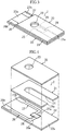
- the first embodiment of the present invention will be initially described with reference to FIG. 1 to FIG. 6 .
- an analytical device X1 comprises a biosensor 2 mounted on a mounting portion 10 and measures the concentration of a specific component in a sample.
- the biosensor 2 as shown in FIG. 3 to FIG. 5 , comprises a cover 20, a spacer 21, and a substrate 22.
- the cover 20 has an orifice 23.
- the spacer 21 is provided with a slit 24.
- the slit 24 is designed for setting a flow channel 25 of the biosensor 2, has a distal end opening 24a, and is linked to the orifice 23. Therefore, the flow channel 25 is linked to the outside via the distal end opening 24a and orifice 23.
- the distal end opening 24a of the cover 20 functions as a sample introduction opening, and the orifice 23 functions as an air release opening. Therefore, when a sample is supplied from the distal end opening (sample introduction opening) 24a, the air present in the flow channel 25 is released to the outside via the orifice 23 and the sample is advanced by a capillary action through the flow channel toward the orifice 23.
- a working electrode 26, a counter-electrode 27, and a reagent section 28 are provided at the upper surface 22a of the substrate 22.
- the working electrode 26 and counter-electrode 27 extend, in the larger part thereof, in the longitudinal direction of the substrate 22, and the end portions 26a, 27a thereof extend in the lateral direction of the substrate 22. Therefore, the working electrode 26 and counter-electrode 27 as a whole have an L-shaped configuration.
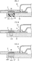
- the end portions 26b, 27b of the working electrode 26 and counter-electrode 27 are designed for contact with a terminal 17 of the analytical device X1, as shown in detail in FIG. 5 .
- the reagent section 28 has, for example, a rectangular shape and, as shown in detail in FIG. 4 and FIG. 5 , connects the end portions 26a, 27a of the working electrode 26 and counter-electrode 27 to each other.
- the reagent section 28 for example comprises a relatively large quantity of an electron conductive substance having a relatively small quantity of an oxidizing-reducing enzyme dispersed therein.
- complexes of iron or Ru can be used as the electron conductive substance.
- Potassium ferricyanide is an example of an iron complex that can be used in this case.
- suitable Ru complexes include those with NH 3 as a ligand.
- the oxidizing-reducing enzyme is selected according to the type of the specific component which is the object of analysis. Examples of specific components include glucose, cholesterol, and lactic acid. Examples of oxidizing-reducing enzymes corresponding to those specific components include glucose dehydrogenase, glucose oxidase, hexokinase, cholesterol dehydrogenase, cholesterol oxidase, lactic acid dehydrogenase, and lactic acid oxidase.
- the analytical device X1 comprises a current measuring unit 11, a temperature detection unit 12, a computation unit 13, a temperature correction unit 14, a display 15, a power source 16, and a pair of terminals (one terminal 17 is depicted in FIG. 5 ) .
- the mounting portion 10 is designed for holding the biosensor 2 and comprises an insertion portion 18 and a table portion 19.
- the insertion portion 18 is designed for inserting the end portion of the biosensor 2.
- the table portion 19 is designed for installing a biosensor 2 and protrudes to the side of the analytical device X1.
- a recess 19a for accommodating the temperature detection portion 12 is provided in the table portion.
- the recess 19a is so provided as to be positioned directly below the reagent portion 28 in the biosensor when the biosensor 2 is mounted on the mounting portion 10.
- the current measuring unit 11 is not clearly shown in the figures. It is connected to a pair of terminals and serves to measure the response current when a voltage is applied between the pair of terminals 17.
- the temperature detection unit 12 is designed for measuring the temperature of the biosensor. As shown in detail in FIG. 5 , this unit is accommodated in the recess 19a of the table portion 19. Therefore, when the biosensor 2 is mounted on the mounting portion, the temperature detection unit is disposed so as to be positioned directly below the reagent portion 28 in the biosensor 2.
- the temperature detection unit 12 comprises a temperature sensor 12A and a thermally conductive portion 12B.
- the temperature sensor 12A has a contact type configuration.
- the thermally conductive portion 12B is formed, for example, from a material with a thermal conductivity of higher than 0.10 cal/(°C ⁇ cm ⁇ sec), preferably, from a material with a thermal conductivity of higher than 0.15 cal/(°C ⁇ cm ⁇ sec).
- the thermally conductive portion 12B covers the temperature sensor 12A, while being in contact with the temperature sensor 12A, and is so disposed that the surface 12b thereof is in the same plane with the surface of the table portion 19. Therefore, when the biosensor 2 is mounted on the mounting portion 10, the thermally conductive portion 12B can be in contact with the substrate 22 of the biosensor 2, and the temperature of the biosensor 2 can be measured with the temperature sensor 12A via the thermally conductive portion 12B. Furthermore, because the thermally conductive portion 12B is disposed so that it covers the temperature sensor 12A, the surface of the temperature sensor 12A is protected from damage or adhesion of foreign matter such as dust.
- the computation unit 13 shown in FIG. 2 computes the concentration of the specific component in the sample based on the measurement results of the current measuring unit 11.
- the computation of concentration is carried out, for example, by fitting the measured current in a calibration curve representing the relationship between a current and a concentration.
- the calibration curve may be also specified as a relationship between a voltage and a concentration.
- the computation of concentration can be conducted by converting the measured current into a voltage based on the same rule and fitting the voltage in the calibration curve.
- the temperature correction unit corrects the computation results obtained in the computation unit 13 according to the temperature information from the temperature detection unit 12.
- An example of such a table is shown in FIG. 6 .
- the table is so compiled that the correction coefficients can be calculated from combinations of temperature and computed concentration considered as parameters.
- the final concentration after temperature correction taking the reaction temperature into account is determined by multiplying the computation results obtained in the computation unit 13 by the selected correction coefficients.
- the aforementioned table is not limited to that shown in FIG. 6 .
- segments of temperature or concentration can be changed.
- the correction coefficients are also not limited to the values shown in FIG. 6 .
- Each of the computation unit 13 and temperature correction unit 14 shown in FIG. 2 can be composed, for example, of a CPU, a RAM, and a ROM, but both the computation unit 13 and temperature correction unit may be also constructed by connecting a plurality of memories such as RAM and ROM to one CPU.
- the display unit 15 shown in FIG. 1 and FIG. 2 is designed to display not only the computation results obtained with the temperature correction unit 14, but also error messages and the like. It is composed, for example, of a LCD.
- the power source 16 shown in FIG. 2 is used for supplying electric power to units 11-15 or for applying a voltage between a pair of terminals 17.
- the power source 16 is composed, for example, of a DC power source such as a dry battery or rechargeable battery.
- the terminals 17 are used when a voltage is applied between the working electrode 26 and counter-electrode 27 of the biosensor 2 or when the electron exchange amount between the working electrode 26 and the electron conductive substance is measured.
- the terminals 17 are so disposed that the distal end portion 17a thereof is brought into contact with end portions 26b, 27b of the working electrode 26 and counter electrode 27 of the biosensor 2 when the biosensor 2 is mounted on the mounting portion 10.
- Each terminal is constructed as a plate spring with a bent conductor tab.
- the distal end portion 17a of the terminal 17 is brought into contact with the end portions 26b, 27b, while applying a push-down pressure to the end portions 26b, 27b of the working electrode 26 and counter-electrode 27.
- the biosensor is strongly attached to the table portion 19 and, therefore, to the temperature detection unit 12.
- the supply of the sample to the reagent portion 28 is confirmed.
- This confirmation can be made based on the electric current measured in the current measuring unit 11. More specifically, it can be made by checking as to whether the current measured in the current measuring unit 11 has reached the predetermined threshold.
- the reagent portion 28 is dissolved by the supply of the sample, and a liquid-phase reaction system is created in the flow channel 25. In the liquid-phase reaction system, the specific component present in the sample is oxidized (or reduced), and the electron conductive substance is reduced (or oxidized).
- the electron conductive substance that was subjected to reduction is oxidized (or reduced), thereby generating an oxidation current (or reduction current). Therefore, measuring the oxidation current (or reduction current) in the current measuring unit 11 makes it possible to confirm that the adequate reaction proceeds in the liquid-phase reaction system. As a result, the supply of the sample to the reagent portion 28 can be confirmed.
- the application of voltage between the working electrode 26 and counter-electrode 27 is terminated.
- the reduced (or oxidized) electron conductive substance is accumulated in the liquid-phase reaction system (flow channel 25).
- a voltage is again applied between the working electrode 26 and counter-electrode 27.
- the electron conductive substance is oxidized (or reduced). Therefore, electron exchange is conducted between the liquid-phase reaction system and the working electrode 26 and the response current can be measured in the current measuring unit 11.
- the response current measured by the current measuring unit 11 is acquired and employed as a basis for computations in the computation unit 13.
- the application of voltage between the working electrode 26 and counter-electrode 27 is still continued even after the supply of the sample to the reagent portion 28 has been confirmed, and the response current measured by the current measuring unit 11 when a prescribed interval has elapsed since the confirmation of sample supply is employed as a basis for computations in the computation unit 13.
- the temperature correction unit 14 determines the correction coefficients based on the temperature information from the temperature detection unit 12 and computation results from the computation unit 13, and those correction coefficients are multiplied by the computation results obtained in the computation unit 13 to determine the final concentration.
- the temperature detection unit 12 was provided in the mounting portion 10 in the analytical device X1 to measure the temperature of the biosensor 2. Therefore, when the temperature of the biosensor 2 is measured, it is not necessary to provide the biosensor 2 with the temperature detection function of a temperature sensor or the like, this feature being beneficial in terms of production cost of the biosensor 2. Further, though the temperature detection unit 12 was provided in the analytical device X1, this temperature detection unit 12 is designed for measuring the temperature of the biosensor 2, rather than the temperature inside the analytical device X1. In particular, if the temperature detection unit 12 is disposed in the vicinity of the biosensor 2, the temperature measured by the temperature detection unit 12 is approximated by the temperature of the biosensor 2.
- the temperature detection unit 12 is provided so as to be located in the region directly below the reagent portion 28 or in the vicinity thereof, then the temperature measured by the temperature detection unit 12 is approximated by the reaction temperature and the reaction temperature can be adequately determined. As a result, the concentration computation can be conducted with good accuracy by taking the reaction temperature into account.
- FIG. 7 to FIG. 9 the elements identical to those of the above-described first embodiment of the present invention are assigned with the same reference numerals and redundant explanation thereof is herein omitted.
- the configuration of the temperature detection unit 12' in the analytical device X2 of the second embodiment is different from that in the analytical device X1 (see FIG. 5 ) relating to the above-described embodiment.
- the temperature sensor 12A and thermally conductive portion 12B are sealed with a resin package 12C to obtain a module, and this module is fit into the table portion 19.
- the temperature detection unit is composed only of the temperature sensor 12A.
- the temperature sensor 12A is so disposed that the surface thereof exposed in the table portion 19. As a result, when the biosensor 2 is mounted on the mounting portion 10, the temperature sensor 12A is brought into direct contact with the biosensor 2.
- the analytical device X4 of the fourth embodiment uses a non-contact sensor as the temperature sensor 12A".
- the temperature detection unit 12" further comprises a transparent element 12D". As a result, damage of the surface of the temperature sensor 12A" can be inhibited and the adhesion of foreign matter to the surface of the temperature sensor 12A" can be inhibited.
- the present invention is not limited to the above-described first to fourth embodiment, and various design modifications can be used.
Landscapes
- Health & Medical Sciences (AREA)
- Chemical & Material Sciences (AREA)
- Life Sciences & Earth Sciences (AREA)
- General Physics & Mathematics (AREA)
- Hematology (AREA)
- Physics & Mathematics (AREA)
- Electrochemistry (AREA)
- Chemical Kinetics & Catalysis (AREA)
- Molecular Biology (AREA)
- Analytical Chemistry (AREA)
- Biochemistry (AREA)
- General Health & Medical Sciences (AREA)
- Immunology (AREA)
- Pathology (AREA)
- Measuring Temperature Or Quantity Of Heat (AREA)
- Investigating Or Analysing Biological Materials (AREA)
- Apparatus Associated With Microorganisms And Enzymes (AREA)
- Automatic Analysis And Handling Materials Therefor (AREA)
Claims (16)
- Analysesystem, umfassend ein Analyseinstrument (2) und eine Temperatur messende Analysevorrichtung, umfassend einen Aufnahmeteil (10) zur Aufnahme des Analyseinstruments (2), so dass es zur Ausgabe von Informationen zur Berechnung fähig ist, eine Berechnungseinheit (13) zum Durchführen einer Berechnung zur Analyse einer Probe auf Basis der genannten Informationen zur Berechnung und eine Temperaturmesseinheit (12) zur Ausgabe von Temperaturinformationen,
wobei das genannte Analyseinstrument (2) einen Endteil und einen Reagensteil (28) hat, die an einem Teil des Analyseinstruments (2) bereitgestellt sind,
wobei der genannte Aufnahmeteil (10) einen Einsetzteil (18) zum Einsetzen des genannten Endteils des genannten Analyseinstruments (2) und einen Tischteil (10) zum Installieren des genannten Analyseinstruments (2) umfasst,
dadurch gekennzeichnet, dass die genannte Temperaturmesseinheit (12) in dem genannten Tischteil (10) angeordnet ist, um in einer Region direkt unter oder in einer Region direkt über dem genannten Reagensteil (28) zu liegen, wenn das genannte Analyseinstrument (2) mit dem in den genannten Einsetzteil (18) eingesetzten Endteil auf dem genannten Aufnahmeteil (10) aufgenommen ist,
und dadurch, dass die Temperatur messende Analysevorrichtung ferner eine Temperaturkorrektureinheit (14) zur Korrektur der in der genannten Berechnungseinheit (13) erhaltenen Berechnungsergebnisse auf Basis der genannten Temperaturinformationen umfasst. - Analysesystem nach Anspruch 1, wobei die genannte Temperaturmesseinheit (12) einen Temperatursensor (12A) des Kontakttyps umfasst.
- Analysesystem nach Anspruch 2, wobei die genannte Temperaturmesseinheit (12) einen wärmeleitfähigen Teil (12B) mit einer Kontaktfläche umfasst, die mit dem genannten Temperatursensor (12A) und dem genannten Analyseinstrument (2) in Kontakt zu bringen ist.
- Analysesystem nach Anspruch 3, wobei der genannte wärmeleitfähige Teil (12B) aus einem Material mit einer Wärmeleitfähigkeit von mehr als 0,10 cal/(°C·cm·s) hergestellt ist.
- Analysesystem nach Anspruch 4, wobei der genannte wärmeleitfähige Teil (12B) aus einem Material mit einer Wärmeleitfähigkeit von mehr als 0,15 cal/(°C·cm·s) hergestellt ist.
- Analysesystem nach Anspruch 4, wobei der genannte wärmeleitfähige Teil (12B) aus Eisen, Kupfer, Aluminium, Legierungen, die wenigstens eines dieser Metalle als die Hauptkomponente enthalten, und Keramik hergestellt ist.
- Analysesystem nach Anspruch 3, wobei der genannte Temperatursensor (12A) und der genannte wärmeleitfähige Teil (12B) in dem genannten Aufnahmeteil (10) angeordnet sind, in dem sie mit einem Kunstharzpaket (12C) versiegelt sind.
- Analysesystem nach Anspruch 2, wobei die genannte Temperaturmesseinheit (12) einen Temperatursensor (12A) des Kontakttyps umfasst und
der Temperatursensor (12A) so angeordnet ist, um mit dem genannten Analyseinstrument (2) in direktem Kontakt zu sein, wenn das genannte analytische Instrument (2) auf dem genannten Aufnahmeteil (10) aufgenommen ist. - Analysesystem nach Anspruch 1, wobei die genannte Temperaturmesseinheit (12) einen Temperatursensor des kontaktfreien Typs umfasst.
- Analysesystem nach Anspruch 1, wobei der genannte Reagensteil (28) ein Enzym umfasst.
- Analysesystem nach Anspruch 10, wobei das genannte Enzym in Bezug auf die Oxidationsreaktion von Glukose eine katalytische Wirkung hat.
- Analysesystem nach Anspruch 1, wobei das genannte Analyseinstrument (2) ein Einwegartikel ist.
- Analysesystem nach Anspruch 1, wobei der genannte Tischteil (10) zur Seite der genannten Analysevorrichtung vorsteht.
- Analysesystem nach Anspruch 1, wobei ein Niederdrückteil (17a) zum Drücken des genannten Analyseinstruments (2) in Bezug auf den genannten Tischteil (10) nach unten in dem genannten Aufnahmeteil (10) angeordnet ist.
- Analysesystem nach Anspruch 14, wobei das genannte Analyseinstrument (2) eine Ausgabeeinheit (17) zum Ausgeben der genannten Informationen zur Berechnung umfasst,
wobei der genannte Niederdrückteil (17a) eine Fähigkeit hat, mit der genannten Ausgabeeinheit (17) in Kontakt gebracht zu werden und die genannten Informationen zur Berechnung einzugeben. - Analysesystem nach Anspruch 15, wobei der genannte Niederdrückteil (17a) eine von einem Leiter gebildete Plattenfeder ist.
Applications Claiming Priority (3)
| Application Number | Priority Date | Filing Date | Title |
|---|---|---|---|
| JP2002009996 | 2002-01-18 | ||
| JP2002009996 | 2002-01-18 | ||
| PCT/JP2003/000225 WO2003062812A1 (fr) | 2002-01-18 | 2003-01-14 | Analyseur comportant une thermosonde |
Publications (3)
| Publication Number | Publication Date |
|---|---|
| EP1467201A1 EP1467201A1 (de) | 2004-10-13 |
| EP1467201A4 EP1467201A4 (de) | 2008-12-24 |
| EP1467201B1 true EP1467201B1 (de) | 2018-10-31 |
Family
ID=27605984
Family Applications (1)
| Application Number | Title | Priority Date | Filing Date |
|---|---|---|---|
| EP03701080.8A Expired - Lifetime EP1467201B1 (de) | 2002-01-18 | 2003-01-14 | Analysegerät mit temperatursensor |
Country Status (5)
| Country | Link |
|---|---|
| US (1) | US7655456B2 (de) |
| EP (1) | EP1467201B1 (de) |
| JP (2) | JP4505837B2 (de) |
| CN (1) | CN100344963C (de) |
| WO (1) | WO2003062812A1 (de) |
Families Citing this family (101)
| Publication number | Priority date | Publication date | Assignee | Title |
|---|---|---|---|---|
| US6036924A (en) | 1997-12-04 | 2000-03-14 | Hewlett-Packard Company | Cassette of lancet cartridges for sampling blood |
| US6391005B1 (en) | 1998-03-30 | 2002-05-21 | Agilent Technologies, Inc. | Apparatus and method for penetration with shaft having a sensor for sensing penetration depth |
| DE10057832C1 (de) * | 2000-11-21 | 2002-02-21 | Hartmann Paul Ag | Blutanalysegerät |
| US8641644B2 (en) | 2000-11-21 | 2014-02-04 | Sanofi-Aventis Deutschland Gmbh | Blood testing apparatus having a rotatable cartridge with multiple lancing elements and testing means |
| US20070100255A1 (en) * | 2002-04-19 | 2007-05-03 | Pelikan Technologies, Inc. | Method and apparatus for body fluid sampling and analyte sensing |
| ES2336081T3 (es) * | 2001-06-12 | 2010-04-08 | Pelikan Technologies Inc. | Dispositivo de puncion de auto-optimizacion con medios de adaptacion a variaciones temporales en las propiedades cutaneas. |
| US7041068B2 (en) | 2001-06-12 | 2006-05-09 | Pelikan Technologies, Inc. | Sampling module device and method |
| US9795747B2 (en) | 2010-06-02 | 2017-10-24 | Sanofi-Aventis Deutschland Gmbh | Methods and apparatus for lancet actuation |
| AU2002348683A1 (en) * | 2001-06-12 | 2002-12-23 | Pelikan Technologies, Inc. | Method and apparatus for lancet launching device integrated onto a blood-sampling cartridge |
| CA2448681C (en) | 2001-06-12 | 2014-09-09 | Pelikan Technologies, Inc. | Integrated blood sampling analysis system with multi-use sampling module |
| ATE497731T1 (de) | 2001-06-12 | 2011-02-15 | Pelikan Technologies Inc | Gerät zur erhöhung der erfolgsrate im hinblick auf die durch einen fingerstich erhaltene blutausbeute |
| US7981056B2 (en) | 2002-04-19 | 2011-07-19 | Pelikan Technologies, Inc. | Methods and apparatus for lancet actuation |
| US8337419B2 (en) | 2002-04-19 | 2012-12-25 | Sanofi-Aventis Deutschland Gmbh | Tissue penetration device |
| ATE485766T1 (de) | 2001-06-12 | 2010-11-15 | Pelikan Technologies Inc | Elektrisches betätigungselement für eine lanzette |
| AU2002312521A1 (en) | 2001-06-12 | 2002-12-23 | Pelikan Technologies, Inc. | Blood sampling apparatus and method |
| US9226699B2 (en) | 2002-04-19 | 2016-01-05 | Sanofi-Aventis Deutschland Gmbh | Body fluid sampling module with a continuous compression tissue interface surface |
| US9427532B2 (en) | 2001-06-12 | 2016-08-30 | Sanofi-Aventis Deutschland Gmbh | Tissue penetration device |
| US7344894B2 (en) | 2001-10-16 | 2008-03-18 | Agilent Technologies, Inc. | Thermal regulation of fluidic samples within a diagnostic cartridge |
| JP4505837B2 (ja) * | 2002-01-18 | 2010-07-21 | アークレイ株式会社 | 温度検出部を備えた分析装置 |
| US8579831B2 (en) | 2002-04-19 | 2013-11-12 | Sanofi-Aventis Deutschland Gmbh | Method and apparatus for penetrating tissue |
| US7976476B2 (en) | 2002-04-19 | 2011-07-12 | Pelikan Technologies, Inc. | Device and method for variable speed lancet |
| US7648468B2 (en) * | 2002-04-19 | 2010-01-19 | Pelikon Technologies, Inc. | Method and apparatus for penetrating tissue |
| US8221334B2 (en) | 2002-04-19 | 2012-07-17 | Sanofi-Aventis Deutschland Gmbh | Method and apparatus for penetrating tissue |
| US7244265B2 (en) * | 2002-04-19 | 2007-07-17 | Pelikan Technologies, Inc. | Method and apparatus for penetrating tissue |
| US7547287B2 (en) | 2002-04-19 | 2009-06-16 | Pelikan Technologies, Inc. | Method and apparatus for penetrating tissue |
| US7331931B2 (en) | 2002-04-19 | 2008-02-19 | Pelikan Technologies, Inc. | Method and apparatus for penetrating tissue |
| US7141058B2 (en) | 2002-04-19 | 2006-11-28 | Pelikan Technologies, Inc. | Method and apparatus for a body fluid sampling device using illumination |
| US9248267B2 (en) | 2002-04-19 | 2016-02-02 | Sanofi-Aventis Deustchland Gmbh | Tissue penetration device |
| US7232451B2 (en) | 2002-04-19 | 2007-06-19 | Pelikan Technologies, Inc. | Method and apparatus for penetrating tissue |
| US7485128B2 (en) | 2002-04-19 | 2009-02-03 | Pelikan Technologies, Inc. | Method and apparatus for penetrating tissue |
| EP1501402A4 (de) | 2002-04-19 | 2008-07-02 | Pelikan Technologies Inc | Vorrichtung und verfahren für eine lanzette mit variabler geschwindigkeit |
| US7909778B2 (en) | 2002-04-19 | 2011-03-22 | Pelikan Technologies, Inc. | Method and apparatus for penetrating tissue |
| US7226461B2 (en) * | 2002-04-19 | 2007-06-05 | Pelikan Technologies, Inc. | Method and apparatus for a multi-use body fluid sampling device with sterility barrier release |
| US7291117B2 (en) | 2002-04-19 | 2007-11-06 | Pelikan Technologies, Inc. | Method and apparatus for penetrating tissue |
| US7410468B2 (en) * | 2002-04-19 | 2008-08-12 | Pelikan Technologies, Inc. | Method and apparatus for penetrating tissue |
| US7901362B2 (en) | 2002-04-19 | 2011-03-08 | Pelikan Technologies, Inc. | Method and apparatus for penetrating tissue |
| US7674232B2 (en) * | 2002-04-19 | 2010-03-09 | Pelikan Technologies, Inc. | Method and apparatus for penetrating tissue |
| US9314194B2 (en) | 2002-04-19 | 2016-04-19 | Sanofi-Aventis Deutschland Gmbh | Tissue penetration device |
| US7374544B2 (en) | 2002-04-19 | 2008-05-20 | Pelikan Technologies, Inc. | Method and apparatus for penetrating tissue |
| US7892183B2 (en) | 2002-04-19 | 2011-02-22 | Pelikan Technologies, Inc. | Method and apparatus for body fluid sampling and analyte sensing |
| US8784335B2 (en) | 2002-04-19 | 2014-07-22 | Sanofi-Aventis Deutschland Gmbh | Body fluid sampling device with a capacitive sensor |
| US7175642B2 (en) | 2002-04-19 | 2007-02-13 | Pelikan Technologies, Inc. | Methods and apparatus for lancet actuation |
| US8702624B2 (en) | 2006-09-29 | 2014-04-22 | Sanofi-Aventis Deutschland Gmbh | Analyte measurement device with a single shot actuator |
| US7491178B2 (en) * | 2002-04-19 | 2009-02-17 | Pelikan Technologies, Inc. | Method and apparatus for penetrating tissue |
| US8372016B2 (en) | 2002-04-19 | 2013-02-12 | Sanofi-Aventis Deutschland Gmbh | Method and apparatus for body fluid sampling and analyte sensing |
| US7717863B2 (en) * | 2002-04-19 | 2010-05-18 | Pelikan Technologies, Inc. | Method and apparatus for penetrating tissue |
| US7229458B2 (en) | 2002-04-19 | 2007-06-12 | Pelikan Technologies, Inc. | Method and apparatus for penetrating tissue |
| US9795334B2 (en) * | 2002-04-19 | 2017-10-24 | Sanofi-Aventis Deutschland Gmbh | Method and apparatus for penetrating tissue |
| US7297122B2 (en) * | 2002-04-19 | 2007-11-20 | Pelikan Technologies, Inc. | Method and apparatus for penetrating tissue |
| US7582099B2 (en) | 2002-04-19 | 2009-09-01 | Pelikan Technologies, Inc | Method and apparatus for penetrating tissue |
| US8267870B2 (en) | 2002-04-19 | 2012-09-18 | Sanofi-Aventis Deutschland Gmbh | Method and apparatus for body fluid sampling with hybrid actuation |
| US7371247B2 (en) | 2002-04-19 | 2008-05-13 | Pelikan Technologies, Inc | Method and apparatus for penetrating tissue |
| US7524293B2 (en) * | 2002-04-19 | 2009-04-28 | Pelikan Technologies, Inc. | Method and apparatus for penetrating tissue |
| US7563232B2 (en) | 2002-04-19 | 2009-07-21 | Pelikan Technologies, Inc. | Method and apparatus for penetrating tissue |
| US8360992B2 (en) | 2002-04-19 | 2013-01-29 | Sanofi-Aventis Deutschland Gmbh | Method and apparatus for penetrating tissue |
| US7265881B2 (en) * | 2002-12-20 | 2007-09-04 | Hewlett-Packard Development Company, L.P. | Method and apparatus for measuring assembly and alignment errors in sensor assemblies |
| US8574895B2 (en) | 2002-12-30 | 2013-11-05 | Sanofi-Aventis Deutschland Gmbh | Method and apparatus using optical techniques to measure analyte levels |
| EP1628567B1 (de) | 2003-05-30 | 2010-08-04 | Pelikan Technologies Inc. | Verfahren und vorrichtung zur injektion von flüssigkeit |
| EP1633235B1 (de) | 2003-06-06 | 2014-05-21 | Sanofi-Aventis Deutschland GmbH | Gerät für die entnahme von körperflüssigkeiten und analyten-nachweis |
| WO2006001797A1 (en) | 2004-06-14 | 2006-01-05 | Pelikan Technologies, Inc. | Low pain penetrating |
| US7604592B2 (en) | 2003-06-13 | 2009-10-20 | Pelikan Technologies, Inc. | Method and apparatus for a point of care device |
| EP1671096A4 (de) | 2003-09-29 | 2009-09-16 | Pelikan Technologies Inc | Verfahren und apparatur für eine verbesserte probeneinfangvorrichtung |
| US9351680B2 (en) | 2003-10-14 | 2016-05-31 | Sanofi-Aventis Deutschland Gmbh | Method and apparatus for a variable user interface |
| US7822454B1 (en) | 2005-01-03 | 2010-10-26 | Pelikan Technologies, Inc. | Fluid sampling device with improved analyte detecting member configuration |
| EP1706026B1 (de) | 2003-12-31 | 2017-03-01 | Sanofi-Aventis Deutschland GmbH | Verfahren und vorrichtung zur verbesserung der fluidströmung und der probennahme |
| WO2006011062A2 (en) | 2004-05-20 | 2006-02-02 | Albatros Technologies Gmbh & Co. Kg | Printable hydrogel for biosensors |
| US9775553B2 (en) * | 2004-06-03 | 2017-10-03 | Sanofi-Aventis Deutschland Gmbh | Method and apparatus for a fluid sampling device |
| WO2005120365A1 (en) | 2004-06-03 | 2005-12-22 | Pelikan Technologies, Inc. | Method and apparatus for a fluid sampling device |
| US8652831B2 (en) | 2004-12-30 | 2014-02-18 | Sanofi-Aventis Deutschland Gmbh | Method and apparatus for analyte measurement test time |
| WO2007090071A2 (en) | 2006-01-27 | 2007-08-09 | Isis Pharmaceuticals, Inc. | 6-modified bicyclic nucleic acid analogs |
| JP5018777B2 (ja) * | 2006-07-05 | 2012-09-05 | パナソニック株式会社 | 液体試料測定方法および装置 |
| US8088097B2 (en) | 2007-11-21 | 2012-01-03 | Glumetrics, Inc. | Use of an equilibrium intravascular sensor to achieve tight glycemic control |
| WO2009119118A1 (ja) | 2008-03-27 | 2009-10-01 | パナソニック株式会社 | 試料測定装置、試料測定システム及び試料測定方法 |
| EP2259038A4 (de) * | 2008-03-27 | 2013-01-02 | Panasonic Corp | Umgebungstemperatur-messverfahren, flüssigkeitsproben-messverfahren und messvorrichtung |
| JP2009250806A (ja) | 2008-04-07 | 2009-10-29 | Panasonic Corp | バイオセンサシステム、センサチップおよび血液試料中の分析物濃度の測定方法 |
| WO2009126900A1 (en) | 2008-04-11 | 2009-10-15 | Pelikan Technologies, Inc. | Method and apparatus for analyte detecting device |
| JP5487467B2 (ja) | 2008-06-16 | 2014-05-07 | パナソニックヘルスケア株式会社 | 分析対象物の測定方法、バイオセンサおよび測定器 |
| CA2740932A1 (en) * | 2008-10-21 | 2010-04-29 | Lifescan, Inc. | Infrared temperature measurement of strip |
| WO2010061629A1 (ja) | 2008-11-28 | 2010-06-03 | パナソニック株式会社 | センサチップ、バイオセンサシステム、生体試料の温度測定方法、血液試料の温度測定方法、血液試料中の分析物の濃度測定方法 |
| US20100187132A1 (en) * | 2008-12-29 | 2010-07-29 | Don Alden | Determination of the real electrochemical surface areas of screen printed electrodes |
| KR101355271B1 (ko) | 2009-01-30 | 2014-01-27 | 파나소닉 주식회사 | 생체 시료의 온도 측정 방법, 생체 시료의 농도 측정 방법, 센서 칩 및 바이오 센서 시스템 |
| US9375169B2 (en) | 2009-01-30 | 2016-06-28 | Sanofi-Aventis Deutschland Gmbh | Cam drive for managing disposable penetrating member actions with a single motor and motor and control system |
| EP2450699A4 (de) * | 2009-06-30 | 2017-05-17 | ARKRAY, Inc. | Analysevorrichtung und analyseverfahren |
| US8568575B2 (en) | 2009-09-02 | 2013-10-29 | Invensys Systems, Inc. | Adjustable, retractable probe insertion assembly |
| WO2011028615A1 (en) * | 2009-09-02 | 2011-03-10 | Invensys Systems, Inc. | Robust potentiometric sensor |
| US20110077477A1 (en) * | 2009-09-30 | 2011-03-31 | Glumetrics, Inc. | Sensors with thromboresistant coating |
| US8467843B2 (en) | 2009-11-04 | 2013-06-18 | Glumetrics, Inc. | Optical sensor configuration for ratiometric correction of blood glucose measurement |
| US9588210B2 (en) * | 2010-02-26 | 2017-03-07 | Arkray, Inc. | Analysis apparatus, analysis method and analysis system |
| JP5338729B2 (ja) * | 2010-03-29 | 2013-11-13 | パナソニック株式会社 | 血液検査装置 |
| US8965476B2 (en) | 2010-04-16 | 2015-02-24 | Sanofi-Aventis Deutschland Gmbh | Tissue penetration device |
| US20120053427A1 (en) * | 2010-08-31 | 2012-03-01 | Glumetrics, Inc. | Optical sensor configuration and methods for monitoring glucose activity in interstitial fluid |
| WO2012127870A1 (ja) | 2011-03-23 | 2012-09-27 | パナソニック株式会社 | 生体情報測定装置 |
| GB201116481D0 (en) * | 2011-09-26 | 2011-11-09 | Cellnovo Ltd | Monitoring devices |
| US9823214B2 (en) * | 2011-11-01 | 2017-11-21 | Panasonic Healthcare Holdings Co., Ltd. | Biological sample measuring apparatus |
| US9528941B2 (en) | 2012-08-08 | 2016-12-27 | Scanadu Incorporated | Method and apparatus for determining analyte concentration by quantifying and interpreting color information captured in a continuous or periodic manner |
| US9171715B2 (en) * | 2012-09-05 | 2015-10-27 | Asm Ip Holding B.V. | Atomic layer deposition of GeO2 |
| WO2015134820A1 (en) * | 2014-03-05 | 2015-09-11 | Scanadu Incorporated | Analyte concentration by quantifying and interpreting color |
| WO2015141510A1 (ja) * | 2014-03-20 | 2015-09-24 | パナソニックヘルスケアホールディングス株式会社 | 生体情報測定装置および生体情報測定装置の制御方法 |
| US9689753B2 (en) * | 2014-05-22 | 2017-06-27 | Roche Diabetes Care, Inc. | Handheld analyte meter with recharging control for improved analyte testing |
| JP7337256B2 (ja) * | 2020-03-24 | 2023-09-01 | 三菱電機株式会社 | 温度検知装置及び該温度検知装置を備えた空気調和機の室内機 |
| CN112461402A (zh) * | 2020-12-08 | 2021-03-09 | 台达电子企业管理(上海)有限公司 | 温度检测系统以及车载充电机 |
Citations (2)
| Publication number | Priority date | Publication date | Assignee | Title |
|---|---|---|---|---|
| US5232667A (en) * | 1992-05-21 | 1993-08-03 | Diametrics Medical, Inc. | Temperature control for portable diagnostic system using a non-contact temperature probe |
| EP1081490A1 (de) * | 1998-05-20 | 2001-03-07 | ARKRAY, Inc. | Verfahren und vorrichtung für elektrochemische messungen unter verwendung von statistischen methoden |
Family Cites Families (21)
| Publication number | Priority date | Publication date | Assignee | Title |
|---|---|---|---|---|
| WO1985002257A1 (en) | 1983-11-10 | 1985-05-23 | Sentech Medical Corporation | Clinical chemistry analyzer |
| JPH0380353A (ja) * | 1989-08-24 | 1991-04-05 | Nippon Telegr & Teleph Corp <Ntt> | 割り込み処理方法とデータチャネル装置 |
| JP2510702Y2 (ja) * | 1989-12-07 | 1996-09-18 | 株式会社エー・アンド・デイ | 使い捨て型化学センサ |
| US5320732A (en) * | 1990-07-20 | 1994-06-14 | Matsushita Electric Industrial Co., Ltd. | Biosensor and measuring apparatus using the same |
| JPH05126792A (ja) * | 1991-11-06 | 1993-05-21 | Toto Ltd | 濃度測定装置とバイオセンサ及び尿中成分測定方法 |
| US5405511A (en) * | 1993-06-08 | 1995-04-11 | Boehringer Mannheim Corporation | Biosensing meter with ambient temperature estimation method and system |
| JPH0810208A (ja) | 1994-06-30 | 1996-01-16 | Toshiba Corp | 食器洗浄機 |
| CN1177740A (zh) * | 1996-07-19 | 1998-04-01 | 泰里迪尼工业公司 | 温度补偿电化学气体探测器和跟踪气体温度变化的方法 |
| FR2760533B1 (fr) * | 1997-03-06 | 1999-05-28 | Alpha Mos Sa | Appareil et procede de caracterisation de liquides |
| US6066243A (en) * | 1997-07-22 | 2000-05-23 | Diametrics Medical, Inc. | Portable immediate response medical analyzer having multiple testing modules |
| US6103033A (en) * | 1998-03-04 | 2000-08-15 | Therasense, Inc. | Process for producing an electrochemical biosensor |
| JP2000019146A (ja) * | 1998-07-06 | 2000-01-21 | Matsushita Electric Ind Co Ltd | 基質の定量法並びにそれに用いるバイオセンサおよび測定装置 |
| JP2001194334A (ja) * | 1999-10-28 | 2001-07-19 | Nec Corp | 生化学センサカートリッジ及びそれを備えた生化学センサ |
| DE19952215C2 (de) | 1999-10-29 | 2001-10-31 | Roche Diagnostics Gmbh | Testelement-Analysesystem |
| US6780296B1 (en) * | 1999-12-23 | 2004-08-24 | Roche Diagnostics Corporation | Thermally conductive sensor |
| DE10032015A1 (de) | 2000-07-01 | 2002-01-10 | Roche Diagnostics Gmbh | Testelement-Analysegerät |
| JP2002050205A (ja) | 2000-08-01 | 2002-02-15 | Eidai Co Ltd | 幅木装置 |
| JP3709919B2 (ja) * | 2000-08-01 | 2005-10-26 | 日本電気株式会社 | 液体試料中の成分の測定装置 |
| JP2002048787A (ja) * | 2000-08-04 | 2002-02-15 | Toto Ltd | 排泄物測定装置の温度校正機構 |
| US6766817B2 (en) | 2001-07-25 | 2004-07-27 | Tubarc Technologies, Llc | Fluid conduction utilizing a reversible unsaturated siphon with tubarc porosity action |
| JP4505837B2 (ja) * | 2002-01-18 | 2010-07-21 | アークレイ株式会社 | 温度検出部を備えた分析装置 |
-
2003
- 2003-01-14 JP JP2003562626A patent/JP4505837B2/ja not_active Expired - Lifetime
- 2003-01-14 EP EP03701080.8A patent/EP1467201B1/de not_active Expired - Lifetime
- 2003-01-14 CN CNB038023199A patent/CN100344963C/zh not_active Expired - Lifetime
- 2003-01-14 US US10/501,797 patent/US7655456B2/en not_active Expired - Lifetime
- 2003-01-14 WO PCT/JP2003/000225 patent/WO2003062812A1/ja not_active Ceased
-
2010
- 2010-01-14 JP JP2010005529A patent/JP4901964B2/ja not_active Expired - Fee Related
Patent Citations (2)
| Publication number | Priority date | Publication date | Assignee | Title |
|---|---|---|---|---|
| US5232667A (en) * | 1992-05-21 | 1993-08-03 | Diametrics Medical, Inc. | Temperature control for portable diagnostic system using a non-contact temperature probe |
| EP1081490A1 (de) * | 1998-05-20 | 2001-03-07 | ARKRAY, Inc. | Verfahren und vorrichtung für elektrochemische messungen unter verwendung von statistischen methoden |
Also Published As
| Publication number | Publication date |
|---|---|
| WO2003062812A1 (fr) | 2003-07-31 |
| US20050019219A1 (en) | 2005-01-27 |
| US7655456B2 (en) | 2010-02-02 |
| EP1467201A4 (de) | 2008-12-24 |
| CN1618015A (zh) | 2005-05-18 |
| EP1467201A1 (de) | 2004-10-13 |
| JP4901964B2 (ja) | 2012-03-21 |
| CN100344963C (zh) | 2007-10-24 |
| JP4505837B2 (ja) | 2010-07-21 |
| JPWO2003062812A1 (ja) | 2005-05-26 |
| JP2010091583A (ja) | 2010-04-22 |
Similar Documents
| Publication | Publication Date | Title |
|---|---|---|
| EP1467201B1 (de) | Analysegerät mit temperatursensor | |
| US7491310B2 (en) | Concentration measuring method and concentration measuring apparatus | |
| KR101566256B1 (ko) | 전기화학적 테스트 스트립 | |
| EP1678490B1 (de) | Verfahren zur reduzierung von interferenzen in einem elektrochemischen sensor unter verwendung von zwei unterschiedlichen angelegten potentialen | |
| AU2006233772B2 (en) | Analyte determination method and analyte meter | |
| US7655119B2 (en) | Meter for use in an improved method of reducing interferences in an electrochemical sensor using two different applied potentials | |
| CN102984999B (zh) | 用于测量样品中分析物的系统和方法 | |
| CN102918388B (zh) | 电化学分析物测量方法和系统 | |
| KR101966611B1 (ko) | 오류 검출을 갖는 포도당 전기화학 측정 방법 | |
| US20030080001A1 (en) | Heated electrochemical cell | |
| US9709521B2 (en) | System and method for measuring an analyte in a sample and correcting for interferents | |
| EP1571442B1 (de) | Analysesystem | |
| US20060042942A1 (en) | Analyzing device | |
| US20180217079A1 (en) | Determining an analyte concentration of a physiological fluid having an interferent | |
| US9261478B2 (en) | System and method for measuring an analyte in a sample and calculating hematocrit-insensitive glucose concentrations | |
| KR100757297B1 (ko) | 빠른 시료주입이 가능한 바이오센서 및 그 센서를 이용한혈당 측정 방법 | |
| KR200435115Y1 (ko) | 빠른 시료주입이 가능한 바이오센서 | |
| US20080169799A1 (en) | Method for biosensor analysis | |
| KR101950161B1 (ko) | 샘플의 분석적 검사를 위한 테스트 엘리먼트 분석 시스템 | |
| KR20190045462A (ko) | 바이오 측정 장치 | |
| HK1091900B (en) | A meter for use in a method of reducing interferences in an electrochemical sensor using two different applied potentials | |
| HK1217537B (en) | System and method for measuring an analyte in a sample and calculating hematocrit-insensitive glucose concentrations |
Legal Events
| Date | Code | Title | Description |
|---|---|---|---|
| PUAI | Public reference made under article 153(3) epc to a published international application that has entered the european phase |
Free format text: ORIGINAL CODE: 0009012 |
|
| 17P | Request for examination filed |
Effective date: 20040716 |
|
| AK | Designated contracting states |
Kind code of ref document: A1 Designated state(s): AT BE BG CH CY CZ DE DK EE ES FI FR GB GR HU IE IT LI LU MC NL PT SE SI SK TR |
|
| AX | Request for extension of the european patent |
Extension state: AL LT LV MK RO |
|
| A4 | Supplementary search report drawn up and despatched |
Effective date: 20081124 |
|
| RIC1 | Information provided on ipc code assigned before grant |
Ipc: G01N 27/416 20060101ALI20081118BHEP Ipc: G01N 27/327 20060101AFI20030805BHEP |
|
| 17Q | First examination report despatched |
Effective date: 20091022 |
|
| RAP1 | Party data changed (applicant data changed or rights of an application transferred) |
Owner name: ARKRAY, INC. |
|
| GRAP | Despatch of communication of intention to grant a patent |
Free format text: ORIGINAL CODE: EPIDOSNIGR1 |
|
| STAA | Information on the status of an ep patent application or granted ep patent |
Free format text: STATUS: GRANT OF PATENT IS INTENDED |
|
| RIC1 | Information provided on ipc code assigned before grant |
Ipc: G01K 1/16 19680901ALI20180417BHEP Ipc: G01N 27/327 19900101AFI20180417BHEP Ipc: G01N 27/416 19900101ALI20180417BHEP |
|
| INTG | Intention to grant announced |
Effective date: 20180518 |
|
| RIN1 | Information on inventor provided before grant (corrected) |
Inventor name: OSHIMAN, EISAKU Inventor name: SHIRAKI, YASUNORI |
|
| GRAS | Grant fee paid |
Free format text: ORIGINAL CODE: EPIDOSNIGR3 |
|
| GRAA | (expected) grant |
Free format text: ORIGINAL CODE: 0009210 |
|
| STAA | Information on the status of an ep patent application or granted ep patent |
Free format text: STATUS: THE PATENT HAS BEEN GRANTED |
|
| AK | Designated contracting states |
Kind code of ref document: B1 Designated state(s): AT BE BG CH CY CZ DE DK EE ES FI FR GB GR HU IE IT LI LU MC NL PT SE SI SK TR |
|
| REG | Reference to a national code |
Ref country code: CH Ref legal event code: EP Ref country code: GB Ref legal event code: FG4D |
|
| REG | Reference to a national code |
Ref country code: AT Ref legal event code: REF Ref document number: 1059996 Country of ref document: AT Kind code of ref document: T Effective date: 20181115 |
|
| REG | Reference to a national code |
Ref country code: DE Ref legal event code: R096 Ref document number: 60351591 Country of ref document: DE |
|
| REG | Reference to a national code |
Ref country code: IE Ref legal event code: FG4D |
|
| REG | Reference to a national code |
Ref country code: CH Ref legal event code: PK Free format text: BERICHTIGUNGEN |
|
| RIC2 | Information provided on ipc code assigned after grant |
Ipc: G01N 27/327 20060101AFI20180417BHEP Ipc: G01K 1/16 20060101ALI20180417BHEP Ipc: G01N 27/416 20060101ALI20180417BHEP |
|
| REG | Reference to a national code |
Ref country code: NL Ref legal event code: MP Effective date: 20181031 |
|
| REG | Reference to a national code |
Ref country code: AT Ref legal event code: MK05 Ref document number: 1059996 Country of ref document: AT Kind code of ref document: T Effective date: 20181031 |
|
| PG25 | Lapsed in a contracting state [announced via postgrant information from national office to epo] |
Ref country code: AT Free format text: LAPSE BECAUSE OF FAILURE TO SUBMIT A TRANSLATION OF THE DESCRIPTION OR TO PAY THE FEE WITHIN THE PRESCRIBED TIME-LIMIT Effective date: 20181031 Ref country code: ES Free format text: LAPSE BECAUSE OF FAILURE TO SUBMIT A TRANSLATION OF THE DESCRIPTION OR TO PAY THE FEE WITHIN THE PRESCRIBED TIME-LIMIT Effective date: 20181031 Ref country code: BG Free format text: LAPSE BECAUSE OF FAILURE TO SUBMIT A TRANSLATION OF THE DESCRIPTION OR TO PAY THE FEE WITHIN THE PRESCRIBED TIME-LIMIT Effective date: 20190131 Ref country code: FI Free format text: LAPSE BECAUSE OF FAILURE TO SUBMIT A TRANSLATION OF THE DESCRIPTION OR TO PAY THE FEE WITHIN THE PRESCRIBED TIME-LIMIT Effective date: 20181031 |
|
| PG25 | Lapsed in a contracting state [announced via postgrant information from national office to epo] |
Ref country code: PT Free format text: LAPSE BECAUSE OF FAILURE TO SUBMIT A TRANSLATION OF THE DESCRIPTION OR TO PAY THE FEE WITHIN THE PRESCRIBED TIME-LIMIT Effective date: 20190301 Ref country code: GR Free format text: LAPSE BECAUSE OF FAILURE TO SUBMIT A TRANSLATION OF THE DESCRIPTION OR TO PAY THE FEE WITHIN THE PRESCRIBED TIME-LIMIT Effective date: 20190201 Ref country code: SE Free format text: LAPSE BECAUSE OF FAILURE TO SUBMIT A TRANSLATION OF THE DESCRIPTION OR TO PAY THE FEE WITHIN THE PRESCRIBED TIME-LIMIT Effective date: 20181031 Ref country code: NL Free format text: LAPSE BECAUSE OF FAILURE TO SUBMIT A TRANSLATION OF THE DESCRIPTION OR TO PAY THE FEE WITHIN THE PRESCRIBED TIME-LIMIT Effective date: 20181031 |
|
| PG25 | Lapsed in a contracting state [announced via postgrant information from national office to epo] |
Ref country code: DK Free format text: LAPSE BECAUSE OF FAILURE TO SUBMIT A TRANSLATION OF THE DESCRIPTION OR TO PAY THE FEE WITHIN THE PRESCRIBED TIME-LIMIT Effective date: 20181031 Ref country code: CZ Free format text: LAPSE BECAUSE OF FAILURE TO SUBMIT A TRANSLATION OF THE DESCRIPTION OR TO PAY THE FEE WITHIN THE PRESCRIBED TIME-LIMIT Effective date: 20181031 |
|
| REG | Reference to a national code |
Ref country code: DE Ref legal event code: R097 Ref document number: 60351591 Country of ref document: DE |
|
| PG25 | Lapsed in a contracting state [announced via postgrant information from national office to epo] |
Ref country code: EE Free format text: LAPSE BECAUSE OF FAILURE TO SUBMIT A TRANSLATION OF THE DESCRIPTION OR TO PAY THE FEE WITHIN THE PRESCRIBED TIME-LIMIT Effective date: 20181031 Ref country code: MC Free format text: LAPSE BECAUSE OF FAILURE TO SUBMIT A TRANSLATION OF THE DESCRIPTION OR TO PAY THE FEE WITHIN THE PRESCRIBED TIME-LIMIT Effective date: 20181031 Ref country code: SK Free format text: LAPSE BECAUSE OF FAILURE TO SUBMIT A TRANSLATION OF THE DESCRIPTION OR TO PAY THE FEE WITHIN THE PRESCRIBED TIME-LIMIT Effective date: 20181031 |
|
| REG | Reference to a national code |
Ref country code: CH Ref legal event code: PL |
|
| PLBE | No opposition filed within time limit |
Free format text: ORIGINAL CODE: 0009261 |
|
| STAA | Information on the status of an ep patent application or granted ep patent |
Free format text: STATUS: NO OPPOSITION FILED WITHIN TIME LIMIT |
|
| PG25 | Lapsed in a contracting state [announced via postgrant information from national office to epo] |
Ref country code: LU Free format text: LAPSE BECAUSE OF NON-PAYMENT OF DUE FEES Effective date: 20190114 |
|
| 26N | No opposition filed |
Effective date: 20190801 |
|
| REG | Reference to a national code |
Ref country code: BE Ref legal event code: MM Effective date: 20190131 |
|
| REG | Reference to a national code |
Ref country code: IE Ref legal event code: MM4A |
|
| PG25 | Lapsed in a contracting state [announced via postgrant information from national office to epo] |
Ref country code: SI Free format text: LAPSE BECAUSE OF FAILURE TO SUBMIT A TRANSLATION OF THE DESCRIPTION OR TO PAY THE FEE WITHIN THE PRESCRIBED TIME-LIMIT Effective date: 20181031 |
|
| PG25 | Lapsed in a contracting state [announced via postgrant information from national office to epo] |
Ref country code: BE Free format text: LAPSE BECAUSE OF NON-PAYMENT OF DUE FEES Effective date: 20190131 |
|
| PG25 | Lapsed in a contracting state [announced via postgrant information from national office to epo] |
Ref country code: CH Free format text: LAPSE BECAUSE OF NON-PAYMENT OF DUE FEES Effective date: 20190131 Ref country code: LI Free format text: LAPSE BECAUSE OF NON-PAYMENT OF DUE FEES Effective date: 20190131 |
|
| PG25 | Lapsed in a contracting state [announced via postgrant information from national office to epo] |
Ref country code: IE Free format text: LAPSE BECAUSE OF NON-PAYMENT OF DUE FEES Effective date: 20190114 |
|
| PG25 | Lapsed in a contracting state [announced via postgrant information from national office to epo] |
Ref country code: TR Free format text: LAPSE BECAUSE OF FAILURE TO SUBMIT A TRANSLATION OF THE DESCRIPTION OR TO PAY THE FEE WITHIN THE PRESCRIBED TIME-LIMIT Effective date: 20181031 |
|
| PG25 | Lapsed in a contracting state [announced via postgrant information from national office to epo] |
Ref country code: CY Free format text: LAPSE BECAUSE OF FAILURE TO SUBMIT A TRANSLATION OF THE DESCRIPTION OR TO PAY THE FEE WITHIN THE PRESCRIBED TIME-LIMIT Effective date: 20181031 |
|
| PG25 | Lapsed in a contracting state [announced via postgrant information from national office to epo] |
Ref country code: HU Free format text: LAPSE BECAUSE OF FAILURE TO SUBMIT A TRANSLATION OF THE DESCRIPTION OR TO PAY THE FEE WITHIN THE PRESCRIBED TIME-LIMIT; INVALID AB INITIO Effective date: 20030114 |
|
| PGFP | Annual fee paid to national office [announced via postgrant information from national office to epo] |
Ref country code: GB Payment date: 20220119 Year of fee payment: 20 Ref country code: DE Payment date: 20220119 Year of fee payment: 20 |
|
| PGFP | Annual fee paid to national office [announced via postgrant information from national office to epo] |
Ref country code: IT Payment date: 20220120 Year of fee payment: 20 Ref country code: FR Payment date: 20220119 Year of fee payment: 20 |
|
| REG | Reference to a national code |
Ref country code: DE Ref legal event code: R071 Ref document number: 60351591 Country of ref document: DE |
|
| REG | Reference to a national code |
Ref country code: GB Ref legal event code: PE20 Expiry date: 20230113 |
|
| PG25 | Lapsed in a contracting state [announced via postgrant information from national office to epo] |
Ref country code: GB Free format text: LAPSE BECAUSE OF EXPIRATION OF PROTECTION Effective date: 20230113 |