EP1467390B1 - Tastenblock zum Einsetzen in eine Bedienfläche eines Haushaltsgerätes - Google Patents
Tastenblock zum Einsetzen in eine Bedienfläche eines Haushaltsgerätes Download PDFInfo
- Publication number
- EP1467390B1 EP1467390B1 EP03029681A EP03029681A EP1467390B1 EP 1467390 B1 EP1467390 B1 EP 1467390B1 EP 03029681 A EP03029681 A EP 03029681A EP 03029681 A EP03029681 A EP 03029681A EP 1467390 B1 EP1467390 B1 EP 1467390B1
- Authority
- EP
- European Patent Office
- Prior art keywords
- keypad
- actuating element
- key cap
- frame
- keypad according
- Prior art date
- Legal status (The legal status is an assumption and is not a legal conclusion. Google has not performed a legal analysis and makes no representation as to the accuracy of the status listed.)
- Expired - Lifetime
Links
Images

Classifications
-
- H—ELECTRICITY
- H01—ELECTRIC ELEMENTS
- H01H—ELECTRIC SWITCHES; RELAYS; SELECTORS; EMERGENCY PROTECTIVE DEVICES
- H01H13/00—Switches having rectilinearly-movable operating part or parts adapted for pushing or pulling in one direction only, e.g. push-button switch
- H01H13/70—Switches having rectilinearly-movable operating part or parts adapted for pushing or pulling in one direction only, e.g. push-button switch having a plurality of operating members associated with different sets of contacts, e.g. keyboard
-
- H—ELECTRICITY
- H01—ELECTRIC ELEMENTS
- H01H—ELECTRIC SWITCHES; RELAYS; SELECTORS; EMERGENCY PROTECTIVE DEVICES
- H01H2221/00—Actuators
- H01H2221/036—Return force
- H01H2221/044—Elastic part on actuator or casing
-
- H—ELECTRICITY
- H01—ELECTRIC ELEMENTS
- H01H—ELECTRIC SWITCHES; RELAYS; SELECTORS; EMERGENCY PROTECTIVE DEVICES
- H01H2229/00—Manufacturing
- H01H2229/064—Eliminating tolerances
Definitions
- the invention relates to a keypad for insertion into an operating surface of a household appliance, in particular a Cover made of glass, stainless steel, aluminum or materials with similar material properties.
- buttons for Setting certain functions individually or as Keypad arranged side by side. It should be noted, that the functional units are spatially coordinated are, so that in or attached to the housing keys and the buttons inside the electronics of the device interact smoothly.
- the assembly of pushbuttons is especially for glass panels difficult as the ones feasible at competitive prices Glass processing techniques with larger manufacturing tolerances connected as, for example, metalworking techniques. Therefore, basically the use a keypad advantageous in which the control surface not needed for the functionality of the keys and accordingly does not need to be specially adapted. Farther it is desirable that the known electronics the devices and their arrangement can remain unchanged and that the keys even when larger manufacturing tolerances interact with this electronics.
- the document DE 197 39 575 discloses a keypad in which are integrally formed on a flexible web pushbuttons, which are housed in openings, for example in a glass panel. Due to the flexible web, a flexible arrangement of the pushbuttons is achieved. About a trained on the pressure switch switch plunger can also operate a more distant electronics. The switch plunger is so generously dimensioned that the button is always pressed when the push button is pressed.
- the corresponding active surfaces are those surfaces or areas on the surface of the key cap and the Actuator on which keycap and actuator upon actuation of the key cap in the direction of actuation touch. That the corresponding active surfaces not connected to each other or loose or against each other In other words, being mobile means that the keycap and the actuator physically separate units or separate components.
- the main advantage of the keypad according to the invention is that through the physical separation of the units keycap and actuating element, the compensation of shape and position tolerances, For example, on manufacturing tolerances of Keypads, the control unit or the electronic Switching unit based, is enabled.
- the actuators can then be in the direction of actuation and / or vertically to the direction of actuation a certain game in the frame or in the key cap, thereby also a actuate a slightly offset switching element or with this can be brought into engagement.
- Another advantage is that the orientation of the keycaps not in the frame by the position of the actuators being affected. This ensures that the keypad outwards always has a uniform surface having.
- Another advantage is that the spring elements to provide the restoring force are formed on the button.
- the electrical switching unit in the previous devices remain unchanged in their arrangement, since they are not needed for the functionality of the keys. Also on The control surface are no complex modifications perform.
- the keypad according to the invention is made built very few simple parts, which he also is relatively inexpensive in the Fier ein.
- the keycap is in the guide frame guided from the inside. That means the keycap enclose the guide frame and lie with areas its inner surface, in particular the inner surface of the side surfaces, at corresponding areas or areas or Points the surface of the guide frame.
- the guide frame prevents twisting of the keycaps in the Frame. This has the advantage of a visually appealing Appearance, as the keys are essentially standing vertically zueinender, on the other hand is the danger Damage to the keys by rubbing together and in the worst case, jamming of the keys is reduced.
- the keycaps have smooth outer surfaces, which in turn is advantageous from an optical point of view.
- this is at least one spring element not in force communication with the actuator.
- the corresponding active surfaces or the separated Units therefore touch each other in an initial position the keycap or a position that the keycap occupies, if no operation, not mandatory.
- that means keycap and actuator can be decoupled from each other when no actuation of the key cap in the direction of actuation takes place.
- the at least one spring element is preferably on the Button cap molded and rests on the frame. That's it Spring element preferably on one or more of the side surfaces the key cap molded. The frame forms then the abutment for the spring element.
- the spring element in a starting position is biased. This will be the Keycaps pressed outwards even when not pressed and all the buttons next to each other are the same Height up. This creates a uniform surface of the keypad and a visually pleasing appearance.
- this is at least a spring element integrally formed on the key cap Strut. It can be particularly advantageous if four struts are molded to the key cap, depending two on the opposite sides of the keycap, the bordering exclusively on the frame. This embodiment is preferred for rectangular keycaps that are relative long such pages, since in this way a uniform reset of the keycaps is achieved.
- the struts can be diagonal to the outer corners of the Run in the middle of these pages. It is both possible that they are at the corners or in the middle of the keycap are formed on this.
- the key cap two struts are formed, one on the opposite Pages.
- This construction is particularly suitable for keys with keycaps that have such short sides. It is possible that the struts this opposite sides in the same or in opposite Direction from an outer corner or the middle of this Pages are diagonal to the other outer corner.
- the frame is together with the guided therein keys in a breakthrough in the control surface used or usable.
- the breakthrough is in its dimensions according to the dimensions of the frame dimensioned. Will the complete keypad in the Submerged user interface is the surface of the keypad almost flush with the surface of the control surface. The gives a pleasing appearance and the control surface is easy to clean.
- the frame is preferably with means for attachment of the keypad in the breakthrough.
- means for attachment of the keypad in the breakthrough for fixation in the control surface, for example, noses, Snap hooks or spring elements may be provided. Farther may be provided means, in particular noses, the serve to press the frame evenly to the surface.
- the key cap is changeable in its position.
- Tolerance range is preferably greater than that through the manufacture of the keypad conditional manufacturing tolerances. Due to the variable position or the mobility or the game of the actuator perpendicular to the direction of actuation and in the direction of actuation can then be For example, positional tolerances of the switching elements of the electrical Balance switching unit. The keycap remains while firmly in their starting position in the frame.
- a locking means As latching means, for example depressions, Grooves, grooves but also noses, hooks or other elevations be provided on the fastening means.
- the locking means serves the fastener with the keypad or to connect to the electrical switching unit, in which it engages with corresponding locking means coming
- the actuating element over the locking means with corresponding connected to the electrical switching unit releasably connected.
- the actuator is then upon actuation of the key cap guided in the electrical switching unit.
- the maximum Hub of the actuator is dependent on the Verrastgeometrie or the embodiment of the corresponding Latching means.
- the actuating element is formed at least in a section in T-shape. at lateral actuation of the button are then on the T-profile the pressure forces in the middle derived. This is especially when using elongated, rectangular Keycaps an advantage.
- the keypad according to the invention is the actuating element about the locking means with corresponding locking means releasably connected to the frame.
- the actuator is then conducted exclusively in the context and cooperates with his side facing away from the key cap with the electric Switching device together.
- the actuating element at the, with the electrical switching unit cooperating End has a broadening, the one has larger diameter than that of the widening adjacent section of the actuator. This will ensures that even with a tolerances due to position Keypad slightly offset switching unit the actuator can interact with the switch.
- FIGS to 19 Corresponding parts and sizes are shown in FIGS to 19 provided with the same reference numerals.
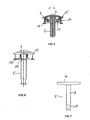
- 1 to 9 show a first advantageous embodiment a keypad according to the invention.
- the keypad 1 in Figure 1 consists of a frame 2 of three arranged in series, rectangular keys 3 encloses.
- the keypad 1 is not limited to three keys 3, but expandable to any number of buttons 3.
- the entire keypad 1 can break into one in a preferably glass, stainless steel or aluminum manufactured operating surface of a household appliance used become.
- FIG 2 and FIG 3 show the individual components of the keypad 1.
- the keycaps 4 and the actuators 5 out.
- Each keycap 4 and each actuator 5 is in the frame run separately.
- On the sides of the keycaps 4, which too adjacent to the adjacent keys are snap hooks 6 provided. With the help of snap hook 6 are the Keycaps 4 locked to the frame 2.
- the maximum stroke the keycaps 4 is through the free path between the Completion of the side surfaces of the key caps 4 in the direction of actuation and the frame 2.
- the actuators 5 are designed as a T-profile, with the Cross struts 7 of the T-shaped actuating elements 5 in the Longitudinal direction of the keycaps 4 extend.
- the actuators 5 are not connected to the keycaps 4.
- the longitudinal struts 8 of the actuators 5 are with the electronic switching unit 9 locked.
- the rectangular one Frame 2 usually has on its narrow outside Snap hooks 10 on which serve the entire Keypad 1 in the control surface of the household appliance too fix.
- the key caps 4 are shown in FIG. 3 in one Starting position.
- the actuators 5 can the key caps 4 or another position between the key caps 4 and the switching element (not here represented) of the electrical switching unit 9 occupy.
- FIG. 4 shows a section along the plane B-B in FIG. 2
- Struts 11 formed from the center of the Run longitudinally diagonally to the outer corners and up rest on the frame 2.
- the button cap 4 By pressing the button cap 4 the struts 11 are deformed, creating a tension is constructed (FIG 4, left button).
- the struts 11 can in the starting position already biased or slightly deformed. Thereby can achieve a uniform height of all keycaps 4, because they are pushed outwards.
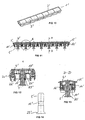
- FIG. 5 The sectional view of the keypad in FIG. 5 shows that on the frame 2 in addition to the snap hook 10 in addition noses 12 are attached, which serve the frame 2 in the Breakthrough in the control surface of the household appliance to fix and press it evenly against the control surface.
- the Arrangement of the snap hook 10 and lugs 12 on the frame 2 is shown in FIG.
- the actuator 5 is a T-profile formed or at least in a section T-shaped. about the cross strut 7 can with lateral actuation of the button the pressure forces are diverted to the middle.
- the longitudinal strut 8 may be round or square and instructs the, remote from the keypad end a locking means 13 in Form of a circumferential depression, with the corresponding Locking means 25 of the electrical switching unit 9 comes into engagement (see FIG 3).
- the rectangular frame 2 of the keypad 1 includes a Edge 14, which encloses the key caps 4 and on which the Noses 12 and snap hook 10 for attachment of the keypad 1 are mounted in the control surface (see FIG and FIG. 5).
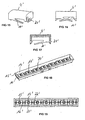
- the edge 14 bent 90 ° outwards, creating a Circumferential Sims 15 is formed (see FIG 9 and FIG 5).
- the height of the edge 14 usually corresponds to the Thickness of the control surface.
- FIG. 9 shows that the longitudinal sides of the edge 14 at the electronic switching device 9 facing side with Cross connections 16 are connected.
- the number of cross connections 16 corresponds to the number of buttons 3.
- Each cross connects 16 carries a guide frame 17 for guidance a key cap 4 in the frame 2.
- the guide frame 17 is substantially rectangular and lower than the edge 14 executed. The dimensions of the guide frame 17 are dependent from the inserted key cap 4th continues the guide frame 17 at the opposite narrow Pages, windows or protrusions 18 in which the snap hooks 6 of the keycaps 4 engage, which the guide frame 17 enclose.
- the guide frame 17 has at each corner, laterally verjetzt to the corners in each case two bulges 19 in the direction of the edge 14 or of the adjacent guide frame 17 on. These bulges 19 are located on the inside of the Keycaps 4 on or the keycaps 4 are along led the bulges 19. As a result, that is the keycaps can not twist and always vertical to stand by each other.
- FIG 9 shows are in the middle of the cross-connections sixteenth Openings 20 attached. Through these openings 20 are the longitudinal struts 8 of the actuators 5 out.
- the keypad 1 can be described below Order to be assembled. First, the frame 2 in Breakthrough in the control panel used and with the help of Snap hooks and noses fixed. Next, the actuators 5 from the outside through the frame 2 therethrough engaged with the electrical switching unit. Subsequently, the keycaps 4 on the guide frame 17 are put on. The fixation of the keycaps takes place by snapping the snap hooks 6 in the windows or projections 18 in the guide frame 17th
- the key cap 4 in the direction of the actuating element 5 moves, so is the interaction of key cap 4 and actuator 5 this in the same direction moved until it is on the switching element of the electrical switching device 9 is present.
- the by further pressing on the Actuator 5 acted upon force is on the Longitudinal strut 7 in the direction of actuation on the switching element the electrical switching unit 9 transmitted, whereby the Switching process is triggered.
- the maximum stroke of the actuator 5 and thus the maximum on the switching element acting force is through the circumferential recess the locking means 13 of the actuating element 5 and the engages engaging latching means 25 of the electrical switching unit 9 limited.
- the key cap 4 If the key cap 4 is released again, it is due to the generated by the struts 11 Restoring force from the actuator 5 away to the outside emotional.
- the actuator 5 may be in contact with the Switching element remain or another position between Take the switching element and key cap 4. Press again the key cap 4 then triggers another switching operation out.
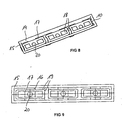
- FIGS. 10 to 19 show a second embodiment of the invention Keypads according to the invention.
- the keypad 1 'in FIG. 10 consists of a frame 2'. the seven arranged in series, rectangular keys 3 'encloses.
- the keypad 1 ' is not on seven keys limited, but expandable to any number of buttons.
- FIG. 11 and FIG. 12 the components of the keypad are shown 1 'shown.
- the keycaps 4' and the actuators 5 'out As in the first embodiment also in this second embodiment in the rectangular Frame 2 'the keycaps 4' and the actuators 5 'out.
- Each keycap 4 'and each actuator 5 ' is managed separately in the frame.
- the actuators 5 ' are not connected to the keycaps 4'. in the Contrary to the first embodiment, here are the actuators 5 'not with the electrical switching unit (not shown here) but with the frame 2 'locked.
- the rectangular frame 2 ' has its narrow outer second Snap hooks 10 'and noses 12', which serve the entire keypad 1 'in the control surface of the household appliance to fix and press (see FIG 12 and FIG. 13).
- FIGS. 15 to 17 show a key cap 4 'for use in the keypad 1 '.
- On the long sides of the key cap 4 ' is ever a strut 11 'formed from a corner of the Long side out to the diagonally opposite corner.
- the struts 11 ' are opposite to each other, As a result, the key cap 4 'evenly outward pressed. But the struts 11 'can also in the same Directed direction.
- the struts 11 ' in the starting position be biased again, creating a uniform height of all keycaps 4 'is achieved.
- windows 21 'are introduced the with the frame 2 'attached snap hook 22' solvable are connected (see also FIG 12).
- the rectangular frame 2 'of the keypad 1' of FIG 11 includes a rim 14 'which encloses the keycaps 4' and at which the lugs 12 'and snap hook 10' for attachment of the keypad are mounted in the control surface (See Figure 18, Figures 11 and 13).
- the edge 14 'with a circumferential Sims 15 'completed see FIG 19 and FIG 11, the on the surface of the operating surface rests.
- FIG. 19 shows that the longitudinal sides of the edge 14 'on its the electronics facing side with cross connections 16 ' are connected, which carry a guide frame 17 'over in each case a key cap 4 'in the frame 2' is performed.
- the guide frame 17 ' is substantially rectangular and lower than the edge 14 'executed.
- the dimensions of the Guide frame 17 ' are dependent on the key cap used 4 '.
- FIG. 18 and FIG. 12 show that at 'the key cap 4' facing surface of the guide frame 17 'in the middle Openings 20 'are mounted, in which the actuators 5 'are introduced.
- a Verrastrahmen 24 At the electrical switching unit facing side of the openings 20 'extends a Verrastrahmen 24 'in the direction of the electrical switching unit.
- the maximum stroke of the actuating element 5 'and thus also the maximum on the switching element (not shown here) acting force is in this second embodiment by the latching means 13 'of the actuating element 5' and the limited engaging latching means 25 '.
- the actuator has at its the switching element of the electric Switching unit facing side a widening 23 'which is larger in diameter than the rest of the actuator 5 '(see also FIG. The broadening allows it also with a slightly offset switching element the force to trigger the switching operation on this transfer.
- the keypad 1 'shown in FIG 10 to 19 can be completely pre-assembled become.
- the preassembled keypad 1 'can then with a handle in the control surface of the household appliance are used, which makes the manufacturing process clear shortened.
Landscapes
- Push-Button Switches (AREA)
- Cookers (AREA)
- Selective Calling Equipment (AREA)
- Electric Ovens (AREA)
- Input From Keyboards Or The Like (AREA)
Applications Claiming Priority (2)
| Application Number | Priority Date | Filing Date | Title |
|---|---|---|---|
| DE10316934A DE10316934B4 (de) | 2003-04-12 | 2003-04-12 | Tastenblock zum Einsetzen in eine Bedienfläche eines Haushaltsgerätes |
| DE10316934 | 2003-04-12 |
Publications (2)
| Publication Number | Publication Date |
|---|---|
| EP1467390A1 EP1467390A1 (de) | 2004-10-13 |
| EP1467390B1 true EP1467390B1 (de) | 2005-11-09 |
Family
ID=32864467
Family Applications (1)
| Application Number | Title | Priority Date | Filing Date |
|---|---|---|---|
| EP03029681A Expired - Lifetime EP1467390B1 (de) | 2003-04-12 | 2003-12-23 | Tastenblock zum Einsetzen in eine Bedienfläche eines Haushaltsgerätes |
Country Status (5)
| Country | Link |
|---|---|
| EP (1) | EP1467390B1 (da) |
| AT (1) | ATE309611T1 (da) |
| DE (2) | DE10316934B4 (da) |
| DK (1) | DK1467390T3 (da) |
| ES (1) | ES2252612T3 (da) |
Families Citing this family (8)
| Publication number | Priority date | Publication date | Assignee | Title |
|---|---|---|---|---|
| DE102005017254A1 (de) * | 2005-04-14 | 2006-10-19 | Leopold Kostal Gmbh & Co. Kg | Tastenanordnung für ein elektrisches oder elektronisches Gerät in einem Kraftfahrzeug |
| EP1713108B1 (de) | 2005-04-14 | 2011-02-09 | Leopold Kostal GmbH & Co. KG | Tastenanordnung für ein elektrisches oder elektronisches Gerät in einem Kraftfahrzeug |
| DE102005017255A1 (de) * | 2005-04-14 | 2006-10-19 | Leopold Kostal Gmbh & Co. Kg | Tastenanordnung für ein elektrisches oder elektronisches Gerät in einem Kraftfahrzeug |
| JP2007316320A (ja) * | 2006-05-25 | 2007-12-06 | Funai Electric Co Ltd | プロジェクタ |
| DE102007045866B3 (de) * | 2007-09-25 | 2008-10-23 | Albrecht Jung Gmbh & Co. Kg | Montageanordnung und deren Verwendung in einem Installationsgerät |
| DE102008041966A1 (de) | 2008-09-10 | 2010-03-11 | BSH Bosch und Siemens Hausgeräte GmbH | Hausgerätevorrichtung |
| EP2282317B1 (en) | 2009-07-29 | 2015-09-30 | Electrolux Home Products Corporation N.V. | Push button switch assembly |
| DE102011119943A1 (de) * | 2011-12-01 | 2013-06-06 | Liebherr-Aerospace Lindenberg Gmbh | Betätigungselement |
Family Cites Families (6)
| Publication number | Priority date | Publication date | Assignee | Title |
|---|---|---|---|---|
| DE19634051C1 (de) * | 1996-08-23 | 1997-08-28 | Telefunken Microelectron | Schalteranordnung mit mindestens einer Drucktaste |
| US5817997A (en) * | 1997-01-24 | 1998-10-06 | Silicon Graphics, Inc. | Power switch plunger mechanism |
| DE19739575C2 (de) * | 1997-09-10 | 2003-10-16 | Aeg Hausgeraete Gmbh | Funktionsblock, insbesondere Tastenblock, für die Bedienfläche eines Geräts sowie Bedienfläche eines Geräts mit einem derartigen Funktionsblock |
| DE19831850A1 (de) * | 1998-07-16 | 2000-01-20 | Aeg Hausgeraete Gmbh | Betätigungselement für ein elektrisches Haushaltsgerät |
| DE19858982C1 (de) * | 1998-12-19 | 2000-04-13 | Ellenberger & Poensgen | Elektrisches Schaltgerät zur Anordnung in einer Einbauöffnung |
| EP1288983A3 (de) * | 2001-09-04 | 2004-06-16 | Siemens Aktiengesellschaft | Elektronisches Gerät, Tastatur für ein elektronisches Gerät und Verfahren zur Positionierung einer Tastatur eines elektronischen Gerätes |
-
2003
- 2003-04-12 DE DE10316934A patent/DE10316934B4/de not_active Expired - Fee Related
- 2003-12-23 EP EP03029681A patent/EP1467390B1/de not_active Expired - Lifetime
- 2003-12-23 AT AT03029681T patent/ATE309611T1/de not_active IP Right Cessation
- 2003-12-23 DK DK03029681T patent/DK1467390T3/da active
- 2003-12-23 DE DE50301612T patent/DE50301612D1/de not_active Expired - Lifetime
- 2003-12-23 ES ES03029681T patent/ES2252612T3/es not_active Expired - Lifetime
Also Published As
| Publication number | Publication date |
|---|---|
| ES2252612T3 (es) | 2006-05-16 |
| DE10316934A1 (de) | 2004-10-28 |
| ATE309611T1 (de) | 2005-11-15 |
| DE10316934B4 (de) | 2007-12-13 |
| DK1467390T3 (da) | 2006-02-13 |
| DE50301612D1 (de) | 2005-12-15 |
| EP1467390A1 (de) | 2004-10-13 |
Similar Documents
| Publication | Publication Date | Title |
|---|---|---|
| DE19853438A1 (de) | Multidirektionale Tastschalteranordnung | |
| DE2351367A1 (de) | Tastatur fuer eine waehlvorrichtung in einem fernmeldegeraet | |
| DE2858237C2 (da) | ||
| EP1467390B1 (de) | Tastenblock zum Einsetzen in eine Bedienfläche eines Haushaltsgerätes | |
| DE2301853C3 (de) | Tastschalter | |
| DE202006019447U1 (de) | Berührungsempfindlicher Schieberegler | |
| DE19634051C1 (de) | Schalteranordnung mit mindestens einer Drucktaste | |
| EP0028000A1 (de) | Drucktaste | |
| DE10309516B3 (de) | Tastenblock mit Federgeometrie | |
| EP1482527B1 (de) | Tastenblock | |
| WO2012168326A1 (de) | Bedieneinheit für eine fahrzeugkomponente | |
| DE29611275U1 (de) | Schalteinrichtung für Fernsprechapparate | |
| DE19836793C2 (de) | Bedienelement zum selektiven Herstellen elektrischer Kontakte | |
| DE4213054B4 (de) | Tastenanordnung | |
| DE4334494C1 (de) | Schlüsselkartenschalter | |
| EP0944104A1 (de) | Grosse, mehrere kleine Tastenfelder abdeckende Drucktaste für ein Keyboard | |
| EP3736930B1 (de) | Tastsensor mit mindestens einer bedienwippe | |
| EP1501108B1 (de) | Elektrischer Mehrwegeschalter | |
| DE3242821A1 (de) | Verschlusskappe fuer einen blattschalter | |
| DE19527093C2 (de) | Tastenanordnung | |
| DE102017214533B3 (de) | Bedieneinrichtung für ein Kraftfahrzeug, insbesondere für einen Kraftwagen, sowie Kraftfahrzeug | |
| EP1715497B1 (de) | Bedienvorrichtung mit einer Schaltmatte | |
| DE2462034C3 (de) | Zum Zusammensetzen von Tastaturen geeignete Taste | |
| DE10349592B4 (de) | Tastenblock zum Einsetzen in eine Blende und Montageanordnung eines Tastenblocks an einer Blende | |
| DE10354043B3 (de) | Tastenblock zum Einsetzen in eine Bedienfläche eines Haushaltgeräts |
Legal Events
| Date | Code | Title | Description |
|---|---|---|---|
| PUAI | Public reference made under article 153(3) epc to a published international application that has entered the european phase |
Free format text: ORIGINAL CODE: 0009012 |
|
| AK | Designated contracting states |
Kind code of ref document: A1 Designated state(s): AT BE BG CH CY CZ DE DK EE ES FI FR GB GR HU IE IT LI LU MC NL PT RO SE SI SK TR |
|
| AX | Request for extension of the european patent |
Extension state: AL LT LV MK |
|
| 17P | Request for examination filed |
Effective date: 20040818 |
|
| 17Q | First examination report despatched |
Effective date: 20041129 |
|
| GRAP | Despatch of communication of intention to grant a patent |
Free format text: ORIGINAL CODE: EPIDOSNIGR1 |
|
| AKX | Designation fees paid |
Designated state(s): AT BE BG CH CY CZ DE DK EE ES FI FR GB GR HU IE IT LI LU MC NL PT RO SE SI SK TR |
|
| GRAS | Grant fee paid |
Free format text: ORIGINAL CODE: EPIDOSNIGR3 |
|
| GRAA | (expected) grant |
Free format text: ORIGINAL CODE: 0009210 |
|
| AK | Designated contracting states |
Kind code of ref document: B1 Designated state(s): AT BE BG CH CY CZ DE DK EE ES FI FR GB GR HU IE IT LI LU MC NL PT RO SE SI SK TR |
|
| PG25 | Lapsed in a contracting state [announced via postgrant information from national office to epo] |
Ref country code: FI Free format text: LAPSE BECAUSE OF FAILURE TO SUBMIT A TRANSLATION OF THE DESCRIPTION OR TO PAY THE FEE WITHIN THE PRESCRIBED TIME-LIMIT Effective date: 20051109 Ref country code: CZ Free format text: LAPSE BECAUSE OF FAILURE TO SUBMIT A TRANSLATION OF THE DESCRIPTION OR TO PAY THE FEE WITHIN THE PRESCRIBED TIME-LIMIT Effective date: 20051109 Ref country code: EE Free format text: LAPSE BECAUSE OF FAILURE TO SUBMIT A TRANSLATION OF THE DESCRIPTION OR TO PAY THE FEE WITHIN THE PRESCRIBED TIME-LIMIT Effective date: 20051109 Ref country code: TR Free format text: LAPSE BECAUSE OF FAILURE TO SUBMIT A TRANSLATION OF THE DESCRIPTION OR TO PAY THE FEE WITHIN THE PRESCRIBED TIME-LIMIT Effective date: 20051109 Ref country code: RO Free format text: LAPSE BECAUSE OF FAILURE TO SUBMIT A TRANSLATION OF THE DESCRIPTION OR TO PAY THE FEE WITHIN THE PRESCRIBED TIME-LIMIT Effective date: 20051109 Ref country code: IE Free format text: LAPSE BECAUSE OF FAILURE TO SUBMIT A TRANSLATION OF THE DESCRIPTION OR TO PAY THE FEE WITHIN THE PRESCRIBED TIME-LIMIT Effective date: 20051109 Ref country code: SK Free format text: LAPSE BECAUSE OF FAILURE TO SUBMIT A TRANSLATION OF THE DESCRIPTION OR TO PAY THE FEE WITHIN THE PRESCRIBED TIME-LIMIT Effective date: 20051109 Ref country code: SI Free format text: LAPSE BECAUSE OF FAILURE TO SUBMIT A TRANSLATION OF THE DESCRIPTION OR TO PAY THE FEE WITHIN THE PRESCRIBED TIME-LIMIT Effective date: 20051109 |
|
| REG | Reference to a national code |
Ref country code: GB Ref legal event code: FG4D Free format text: NOT ENGLISH |
|
| REG | Reference to a national code |
Ref country code: CH Ref legal event code: EP |
|
| REG | Reference to a national code |
Ref country code: CH Ref legal event code: NV Representative=s name: TROESCH SCHEIDEGGER WERNER AG |
|
| PGFP | Annual fee paid to national office [announced via postgrant information from national office to epo] |
Ref country code: AT Payment date: 20051213 Year of fee payment: 3 |
|
| PGFP | Annual fee paid to national office [announced via postgrant information from national office to epo] |
Ref country code: ES Payment date: 20051214 Year of fee payment: 3 |
|
| REG | Reference to a national code |
Ref country code: IE Ref legal event code: FG4D Free format text: LANGUAGE OF EP DOCUMENT: GERMAN |
|
| REF | Corresponds to: |
Ref document number: 50301612 Country of ref document: DE Date of ref document: 20051215 Kind code of ref document: P |
|
| REG | Reference to a national code |
Ref country code: DE Ref legal event code: R096 Ref document number: 50301612 Country of ref document: DE Effective date: 20051215 |
|
| PG25 | Lapsed in a contracting state [announced via postgrant information from national office to epo] |
Ref country code: CY Free format text: LAPSE BECAUSE OF FAILURE TO SUBMIT A TRANSLATION OF THE DESCRIPTION OR TO PAY THE FEE WITHIN THE PRESCRIBED TIME-LIMIT Effective date: 20051223 |
|
| PG25 | Lapsed in a contracting state [announced via postgrant information from national office to epo] |
Ref country code: MC Free format text: LAPSE BECAUSE OF NON-PAYMENT OF DUE FEES Effective date: 20051231 Ref country code: BE Free format text: LAPSE BECAUSE OF NON-PAYMENT OF DUE FEES Effective date: 20051231 |
|
| PG25 | Lapsed in a contracting state [announced via postgrant information from national office to epo] |
Ref country code: LU Free format text: LAPSE BECAUSE OF NON-PAYMENT OF DUE FEES Effective date: 20060109 |
|
| PG25 | Lapsed in a contracting state [announced via postgrant information from national office to epo] |
Ref country code: GR Free format text: LAPSE BECAUSE OF FAILURE TO SUBMIT A TRANSLATION OF THE DESCRIPTION OR TO PAY THE FEE WITHIN THE PRESCRIBED TIME-LIMIT Effective date: 20060209 Ref country code: BG Free format text: LAPSE BECAUSE OF FAILURE TO SUBMIT A TRANSLATION OF THE DESCRIPTION OR TO PAY THE FEE WITHIN THE PRESCRIBED TIME-LIMIT Effective date: 20060209 |
|
| REG | Reference to a national code |
Ref country code: DK Ref legal event code: T3 |
|
| REG | Reference to a national code |
Ref country code: SE Ref legal event code: TRGR |
|
| GBT | Gb: translation of ep patent filed (gb section 77(6)(a)/1977) |
Effective date: 20060220 |
|
| PG25 | Lapsed in a contracting state [announced via postgrant information from national office to epo] |
Ref country code: PT Free format text: LAPSE BECAUSE OF FAILURE TO SUBMIT A TRANSLATION OF THE DESCRIPTION OR TO PAY THE FEE WITHIN THE PRESCRIBED TIME-LIMIT Effective date: 20060410 |
|
| PG25 | Lapsed in a contracting state [announced via postgrant information from national office to epo] |
Ref country code: HU Free format text: LAPSE BECAUSE OF FAILURE TO SUBMIT A TRANSLATION OF THE DESCRIPTION OR TO PAY THE FEE WITHIN THE PRESCRIBED TIME-LIMIT Effective date: 20060510 |
|
| REG | Reference to a national code |
Ref country code: ES Ref legal event code: FG2A Ref document number: 2252612 Country of ref document: ES Kind code of ref document: T3 |
|
| REG | Reference to a national code |
Ref country code: IE Ref legal event code: FD4D |
|
| ET | Fr: translation filed | ||
| PLBE | No opposition filed within time limit |
Free format text: ORIGINAL CODE: 0009261 |
|
| STAA | Information on the status of an ep patent application or granted ep patent |
Free format text: STATUS: NO OPPOSITION FILED WITHIN TIME LIMIT |
|
| 26N | No opposition filed |
Effective date: 20060810 |
|
| REG | Reference to a national code |
Ref country code: DE Ref legal event code: R097 Ref document number: 50301612 Country of ref document: DE Effective date: 20060810 |
|
| PG25 | Lapsed in a contracting state [announced via postgrant information from national office to epo] |
Ref country code: AT Free format text: LAPSE BECAUSE OF NON-PAYMENT OF DUE FEES Effective date: 20061223 |
|
| BERE | Be: lapsed |
Owner name: ELECTROLUX HOME PRODUCTS CORPORATION N.V. Effective date: 20051231 |
|
| REG | Reference to a national code |
Ref country code: ES Ref legal event code: FD2A Effective date: 20061226 |
|
| PG25 | Lapsed in a contracting state [announced via postgrant information from national office to epo] |
Ref country code: ES Free format text: LAPSE BECAUSE OF NON-PAYMENT OF DUE FEES Effective date: 20061226 |
|
| PGFP | Annual fee paid to national office [announced via postgrant information from national office to epo] |
Ref country code: CH Payment date: 20081218 Year of fee payment: 6 Ref country code: DK Payment date: 20081218 Year of fee payment: 6 Ref country code: NL Payment date: 20081219 Year of fee payment: 6 |
|
| PGFP | Annual fee paid to national office [announced via postgrant information from national office to epo] |
Ref country code: SE Payment date: 20081215 Year of fee payment: 6 |
|
| PGFP | Annual fee paid to national office [announced via postgrant information from national office to epo] |
Ref country code: GB Payment date: 20081223 Year of fee payment: 6 |
|
| REG | Reference to a national code |
Ref country code: NL Ref legal event code: V1 Effective date: 20100701 |
|
| EUG | Se: european patent has lapsed | ||
| REG | Reference to a national code |
Ref country code: CH Ref legal event code: PL |
|
| REG | Reference to a national code |
Ref country code: DK Ref legal event code: EBP |
|
| GBPC | Gb: european patent ceased through non-payment of renewal fee |
Effective date: 20091223 |
|
| PG25 | Lapsed in a contracting state [announced via postgrant information from national office to epo] |
Ref country code: LI Free format text: LAPSE BECAUSE OF NON-PAYMENT OF DUE FEES Effective date: 20091231 Ref country code: CH Free format text: LAPSE BECAUSE OF NON-PAYMENT OF DUE FEES Effective date: 20091231 Ref country code: NL Free format text: LAPSE BECAUSE OF NON-PAYMENT OF DUE FEES Effective date: 20100701 |
|
| PG25 | Lapsed in a contracting state [announced via postgrant information from national office to epo] |
Ref country code: GB Free format text: LAPSE BECAUSE OF NON-PAYMENT OF DUE FEES Effective date: 20091223 |
|
| PG25 | Lapsed in a contracting state [announced via postgrant information from national office to epo] |
Ref country code: DK Free format text: LAPSE BECAUSE OF NON-PAYMENT OF DUE FEES Effective date: 20100104 |
|
| PG25 | Lapsed in a contracting state [announced via postgrant information from national office to epo] |
Ref country code: SE Free format text: LAPSE BECAUSE OF NON-PAYMENT OF DUE FEES Effective date: 20091224 |
|
| REG | Reference to a national code |
Ref country code: FR Ref legal event code: CA Effective date: 20120116 |
|
| REG | Reference to a national code |
Ref country code: DE Ref legal event code: R082 Ref document number: 50301612 Country of ref document: DE Representative=s name: GERHARD BAUMGARTL, DE Ref country code: DE Ref legal event code: R082 Ref document number: 50301612 Country of ref document: DE Representative=s name: BAUMGARTL, GERHARD, DIPL.-ING.UNIV., DE |
|
| PGFP | Annual fee paid to national office [announced via postgrant information from national office to epo] |
Ref country code: FR Payment date: 20130130 Year of fee payment: 10 |
|
| REG | Reference to a national code |
Ref country code: FR Ref legal event code: ST Effective date: 20140829 |
|
| PG25 | Lapsed in a contracting state [announced via postgrant information from national office to epo] |
Ref country code: FR Free format text: LAPSE BECAUSE OF NON-PAYMENT OF DUE FEES Effective date: 20131231 |
|
| PGFP | Annual fee paid to national office [announced via postgrant information from national office to epo] |
Ref country code: DE Payment date: 20221213 Year of fee payment: 20 |
|
| PGFP | Annual fee paid to national office [announced via postgrant information from national office to epo] |
Ref country code: IT Payment date: 20221228 Year of fee payment: 20 |
|
| P01 | Opt-out of the competence of the unified patent court (upc) registered |
Effective date: 20230625 |
|
| REG | Reference to a national code |
Ref country code: DE Ref legal event code: R071 Ref document number: 50301612 Country of ref document: DE |