EP1467461A1 - "verfahren zum erkennen von hindernissen, die durch elektrische fensterheber und ähnliche einrichtungen verursacht werden, unter verwendung von fuzzy-logik-algorithmen" - Google Patents
"verfahren zum erkennen von hindernissen, die durch elektrische fensterheber und ähnliche einrichtungen verursacht werden, unter verwendung von fuzzy-logik-algorithmen" Download PDFInfo
- Publication number
- EP1467461A1 EP1467461A1 EP01989629A EP01989629A EP1467461A1 EP 1467461 A1 EP1467461 A1 EP 1467461A1 EP 01989629 A EP01989629 A EP 01989629A EP 01989629 A EP01989629 A EP 01989629A EP 1467461 A1 EP1467461 A1 EP 1467461A1
- Authority
- EP
- European Patent Office
- Prior art keywords
- motor
- current
- mobile element
- fuzzy logic
- intensity
- Prior art date
- Legal status (The legal status is an assumption and is not a legal conclusion. Google has not performed a legal analysis and makes no representation as to the accuracy of the status listed.)
- Withdrawn
Links
- 238000000034 method Methods 0.000 title claims abstract description 32
- 238000001514 detection method Methods 0.000 claims description 23
- 238000006073 displacement reaction Methods 0.000 claims description 8
- 230000010355 oscillation Effects 0.000 claims description 6
- 238000005070 sampling Methods 0.000 claims description 3
- 238000011156 evaluation Methods 0.000 claims description 2
- 238000004590 computer program Methods 0.000 claims 4
- 230000006870 function Effects 0.000 description 11
- 230000000694 effects Effects 0.000 description 5
- 230000009467 reduction Effects 0.000 description 5
- 230000004044 response Effects 0.000 description 5
- 238000010010 raising Methods 0.000 description 4
- 238000007726 management method Methods 0.000 description 3
- 230000007246 mechanism Effects 0.000 description 3
- 230000009471 action Effects 0.000 description 2
- 230000005540 biological transmission Effects 0.000 description 2
- 238000004364 calculation method Methods 0.000 description 2
- 230000000712 assembly Effects 0.000 description 1
- 238000000429 assembly Methods 0.000 description 1
- 230000008859 change Effects 0.000 description 1
- 230000007423 decrease Effects 0.000 description 1
- 230000001419 dependent effect Effects 0.000 description 1
- 230000008569 process Effects 0.000 description 1
- 230000035484 reaction time Effects 0.000 description 1
- 230000001131 transforming effect Effects 0.000 description 1
Images

Classifications
-
- H—ELECTRICITY
- H02—GENERATION; CONVERSION OR DISTRIBUTION OF ELECTRIC POWER
- H02H—EMERGENCY PROTECTIVE CIRCUIT ARRANGEMENTS
- H02H7/00—Emergency protective circuit arrangements specially adapted for specific types of electric machines or apparatus or for sectionalised protection of cable or line systems, and effecting automatic switching in the event of an undesired change from normal working conditions
- H02H7/08—Emergency protective circuit arrangements specially adapted for specific types of electric machines or apparatus or for sectionalised protection of cable or line systems, and effecting automatic switching in the event of an undesired change from normal working conditions for dynamo-electric motors
- H02H7/085—Emergency protective circuit arrangements specially adapted for specific types of electric machines or apparatus or for sectionalised protection of cable or line systems, and effecting automatic switching in the event of an undesired change from normal working conditions for dynamo-electric motors against excessive load
- H02H7/0851—Emergency protective circuit arrangements specially adapted for specific types of electric machines or apparatus or for sectionalised protection of cable or line systems, and effecting automatic switching in the event of an undesired change from normal working conditions for dynamo-electric motors against excessive load for motors actuating a movable member between two end positions, e.g. detecting an end position or obstruction by overload signal
-
- E—FIXED CONSTRUCTIONS
- E05—LOCKS; KEYS; WINDOW OR DOOR FITTINGS; SAFES
- E05F—DEVICES FOR MOVING WINGS INTO OPEN OR CLOSED POSITION; CHECKS FOR WINGS; WING FITTINGS NOT OTHERWISE PROVIDED FOR, CONCERNED WITH THE FUNCTIONING OF THE WING
- E05F15/00—Power-operated mechanisms for wings
- E05F15/40—Safety devices, e.g. detection of obstructions or end positions
- E05F15/41—Detection by monitoring transmitted force or torque; Safety couplings with activation dependent upon torque or force, e.g. slip couplings
-
- E—FIXED CONSTRUCTIONS
- E05—LOCKS; KEYS; WINDOW OR DOOR FITTINGS; SAFES
- E05Y—INDEXING SCHEME ASSOCIATED WITH SUBCLASSES E05D AND E05F, RELATING TO CONSTRUCTION ELEMENTS, ELECTRIC CONTROL, POWER SUPPLY, POWER SIGNAL OR TRANSMISSION, USER INTERFACES, MOUNTING OR COUPLING, DETAILS, ACCESSORIES, AUXILIARY OPERATIONS NOT OTHERWISE PROVIDED FOR, APPLICATION THEREOF
- E05Y2900/00—Application of doors, windows, wings or fittings thereof
- E05Y2900/50—Application of doors, windows, wings or fittings thereof for vehicles
- E05Y2900/53—Type of wing
- E05Y2900/55—Windows
-
- H—ELECTRICITY
- H02—GENERATION; CONVERSION OR DISTRIBUTION OF ELECTRIC POWER
- H02H—EMERGENCY PROTECTIVE CIRCUIT ARRANGEMENTS
- H02H1/00—Details of emergency protective circuit arrangements
- H02H1/0092—Details of emergency protective circuit arrangements concerning the data processing means, e.g. expert systems, neural networks
Definitions
- the present invention falls within the field of control methods for electromechanical assemblies and provides a method and means for controlled management of a mobile element, driven by an electric motor with a safety mechanism to avoid an injuring action by said element whether against a part or limb of a user, causing crushing, or against an object or structural part against which said mobile element might be susceptible of colliding in its movement, immediately and automatically adopting in the face of such an event suitable countermeasures, thus stopping and reversing the displacement movement of said mobile element.
- the invention is particularly applicable to a window panel opening device for a vehicle, driven by a DC electric motor with a multipolar permanent magnet, with a safety mechanism so as to not entrap and/or exercise a crushing force on an object interposed in the trajectory of said window pane, such as a limb or part of a person, even though its field of application can be generalised to any kind of mobile panel or window pane driven by an electric motor of such features, being its main objects precision in detection and speed of response and consequently the possibility it offers for the near-immediate adoption of the aforementioned countermeasures to avoid said non-desired entrapment or crushing situation and progress thereof.
- the proposed method is also adequate for controlling an electromechanically guided seat, avoiding collisions against other vehicle parts or strikes against user parts eventually interposed in the trajectory of the mobile element.
- the invention also provides some programs, loadable into the internal memory of a computer, to perform several of the steps of the method according to the invention, particularly the entrapment or collision detection algorithm, and a velocity control auxiliary algorithm.
- Patent US-A-6273492 refers to an operative mechanism to actuate the top of a convertible vehicle, where, in the case of use of a DC motor, it is proposed that an electronic control performs detection and calculation of voltage and current peaks by means of, among several alternatives, switching the motor (ripple counting technique).
- the invention refers to a method for the controlled management of a moving element, driven by an electric motor, with anti-entrapment or anti-collision safety, said element being mobile, e.g. a vehicle's window pane or panel, a movable seat or the like, which is conveniently guided and is driven by a DC electric motor with a multipolar permanent magnet.
- the method comprises three differentiated parts: detection of the rippling peaks of the current to determine the position and velocity of the movable element to be controlled; control of the velocity and detection of a situation of entrapment or collision, using for the last two parts a fuzzy logic algorithm.
- a base of rules to implement a first fuzzy logic algorithm for the detection of entrapment or collision situations has been built.
- Setting of the fuzzy terms used in the algorithm has been performed based on the experimental setting.
- said DC electric motor is formed by multiple poles, its polarisation current shows continuous rippling.
- This rippling has been used, in the first place, to determine the window's position (by counting the rippling peaks, according to the ripple counting technique, known in itself) and to calculate the relative increment of the current intensity.
- said increment corresponds to measures taken in one of the rippling peaks (it is always measured in a peak corresponding to the same motor pole).
- the performance of detection of a situation of entrapment of an object or limb interposed in the cited mobile element's travel or of a possible collision of said mobile element is proposed by means of a first algorithm based on fuzzy logic whose inputs are the cited mobile element's position and the increments that may take place in the current consumed by the motor.
- the relative increase of the current intensity occurring at one turn of the motor and said relative increase of the intensity generated after a later, near turn of the motor, especially the third, immediately subsequent, i.e. the eventual increments of the intensity in one turn and in three turns of the motor are considered.
- the information on the mobile element's position is known at every moment through detection of the motor's polarisation current rippling by means of the variation of the sampling frequency.
- the invention also proposes an additional step of control of the mobile element's velocity, in closed loop, using a second fuzzy logic algorithm with information input to the same on a desired or reference velocity, and evaluation of the deviation relative to said reference of the actual velocity.
- the fuzzy logic system used has as inputs the mobile element's velocity at every instant and the desired velocity for that instant, and outputs the duty cycle of the PWM.
- Velocity control through fuzzy logic allows a small response time to load variations applied to the motor, by which a rather precise velocity control is obtained, with little use of the resources of a microcontroller used for its implementation.
- the method works in such a way that, when detecting an increase in the motor's demand current intensity of a certain slope, the power fed to the motor decreases instantaneously. Then, two possible evolutions of said intensity may occur, a relevant reduction in the slope, in which case the reason for that increase in intensity would be due to a velocity-dependent friction or to a slight reduction in the slope indicative of the existence of a load independent of the velocity, there being detected an entrapment or a collision.
- the polarisation current rippling peaks of said motor measured for a same motor inductor i.e. those intensity values having the same phase within the oscillation of the current, are used.
- the duty cycle of the motor's feed current is reduced at 90 per cent by means of PWM (pulse width modulation) to discern, then applying again said first fuzzy logic algorithm, whether said current intensity increment, such as a sudden increase, is due to an external force applied to the mobile element or to a stress derived from friction of said mobile element with some guiding parts thereof on its displacement.
- PWM pulse width modulation
- Fig. 1 the forces acting on a window during an entrapment or pinch situation are schematically shown.
- Fig. 2 the current differences between to consecutive intensity samples are illustrated, showing that when a force is applied, the graph does not show any noticeable change.
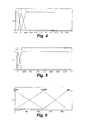
- Figs. 4 to 6 illustrate the fuzzy logic system's descriptive membership functions used for pinch detection, from which the basis for its rules will be disclosed.
- the membership functions for the maximum input 10 are shown
- Fig. 5 the membership functions of the maximum input 30
- Fig. 6 the membership functions of the position input.
- the entrapment and/or possible crushing of and object by a vehicle's window when raising it in automatic mode will generally be designated as pinch.
- this object can be a part of the human body, such as a hand or a finger, or even the neck. Therefore, in the example being explained, the object of every anti-pinch or control management method of a mobile element, conveniently guided and driven by a DC electric motor, such as a window, is to avoid this situation. In order to do so, the control system must be capable of detecting the presence of any object being in the window's trajectory.
- the proposed control method must perform the following actions:
- the last function is the one of hardest execution considering that the method has to be capable of detecting a force of 60 N applied to the window in a time of 10 ms, according to the sector's normative specifications.
- the invention proposes performing pinch detection by means of a first algorithm based on fuzzy logic using as input the information provided by the current intensity that reaches the window's motor and by the position.
- the intensity value of the current consumed by the motor depends on the force exerted on the window, thus increasing the force increases the current.
- the entrapment will create a sudden increment of the current, which in principle should be easily detectable whether the value reached by the motor's current in a normal operation regime is known.
- the friction that the window suffers that makes the total force not constant during the whole raising process.
- This friction under real conditions may vary due to the condition of the window's frame and guides, the effect of the ambient temperature, other climatic conditions and additional reasons.
- said current value may vary in a rather unpredictable manner during different moments in the car's life. This causes that a fixed reference value with which to compare the instantaneous value of the motor's intensity, in order to detect an entrapment condition, cannot be used.
- Fig. 1 the scheme of the forces acting on the window during an entrapment is shown.
- W electric V ⁇ I ⁇ t
- I the motor's current intensity
- t the time.
- W window F total ⁇ s
- F total the force transmitted by the motor to the window
- s the space travelled by the window.
- s and t can be related through the motor's angular velocity or its inverse, the period T.
- the first parameter is useful since in the great majority of cases entrapment occurs in the upper part of the window's run, i.e. when it is near the upper frame. Therefore, it is intended for the system to be a lot more sensible in the final zone of the window's run.
- the window's position can be known at every moment by counting the intensity pulses related to the motor's multipolar nature (ripple counting technique, known in itself).
- the second factor the relative increase of the intensity, will allow detecting sudden increments in the force exerted on the window.
- the calculation of this parameter can seem simple, by simply making a subtraction between two values of the intensities of the currents, certain problems arise if the intensity values of the current to be subtracted are not properly selected.
- the first solution analysed by the inventors was that of subtracting the present current intensity value to the current intensity value sampled in the preceding instant. However, it was confirmed that the obtained result is affected by the current rippling. According to the sampling frequency used, the intensity differences will be affected by higher frequency variations associated to the effect of the motor poles, situation reflected in Fig 2 of the drawings.
- the first solution although apparently simpler, has two drawbacks with regard to the second one, which are: the lower precision when detecting a pinch and, therefore, a longer response time, and the need to use more memory and more time of a microcontroller used in the support equipment for implementing said solution.
- Using only the peaks for pinch detection involves a limitation in the frequency at which the method can operate (the anti-pinch algorithm's operating range), as it will only check whether pinching occurs each time a peak occurs. However, this is compensated by the precision attained.
- the inputs to the fuzzy system are: the window's position, the relative increase of the current intensity at one turn of the motor, and the relative increase of the current intensity at three turns of the motor.
- this signal's value has been calculated, under different friction conditions and taking into account the whole window run, including an entrapment at the end.
- the average of the signal's values before reaching the pinching is calculated.
- This average value has been used for placing the middle point of the membership function Z (zero, it is the middle one).
- the width of this membership function, corresponding to the middle points of the other two membership functions, has been set depending on the system's response according to the experimental results.
- the membership functions of the input corresponding to the position have been chosen dividing the total space travelled by the window in three areas. Reflected in the basis for the rules is that the sector where pinching is more likely to occur is the area nearest the window frame.
- the fuzzy logic system used has the features which reflect the membership functions of Figs. 4, 5, and 6, which are self-explanatory, there being indicated in the case of the first two Figs., the probability in the ordinates, and the difference detected between intensities in abcissas, and in the third Fig, in its axis of abcissas the number of counted rippling peaks (ripples).
- the proposed fuzzy detection system in the implementation Example described, will use as inputs the position of the window, the relative increase of the current intensity with regard to a turn and with regard to three turns of the motor, and will use the 90% duty cycle reduction in order to discern between sudden increases in friction and external forces applied to the window.
- a 30 to 50 per cent reduction of the motor's velocity by means of PWM can be performed in order to discern, applying again said first fuzzy logic algorithm, whether said relative increment of the current intensity, such as a sudden intensity increase, is due to an external force applied to the mobile element or to a stress derived from said mobile element's friction with some guiding parts thereof in its displacement.
Landscapes
- Window Of Vehicle (AREA)
- Power-Operated Mechanisms For Wings (AREA)
Applications Claiming Priority (1)
| Application Number | Priority Date | Filing Date | Title |
|---|---|---|---|
| PCT/ES2001/000508 WO2003063318A1 (es) | 2001-12-27 | 2001-12-27 | Metodo de detección de atrapamientos causados por elevalunas motorizados y similares, mediante algoritmos de lósica borrosa |
Publications (1)
| Publication Number | Publication Date |
|---|---|
| EP1467461A1 true EP1467461A1 (de) | 2004-10-13 |
Family
ID=27589247
Family Applications (1)
| Application Number | Title | Priority Date | Filing Date |
|---|---|---|---|
| EP01989629A Withdrawn EP1467461A1 (de) | 2001-12-27 | 2001-12-27 | "verfahren zum erkennen von hindernissen, die durch elektrische fensterheber und ähnliche einrichtungen verursacht werden, unter verwendung von fuzzy-logik-algorithmen" |
Country Status (3)
| Country | Link |
|---|---|
| US (1) | US7359783B2 (de) |
| EP (1) | EP1467461A1 (de) |
| WO (1) | WO2003063318A1 (de) |
Cited By (2)
| Publication number | Priority date | Publication date | Assignee | Title |
|---|---|---|---|---|
| US8493081B2 (en) | 2009-12-08 | 2013-07-23 | Magna Closures Inc. | Wide activation angle pinch sensor section and sensor hook-on attachment principle |
| US9234979B2 (en) | 2009-12-08 | 2016-01-12 | Magna Closures Inc. | Wide activation angle pinch sensor section |
Families Citing this family (18)
| Publication number | Priority date | Publication date | Assignee | Title |
|---|---|---|---|---|
| US8060308B2 (en) * | 1997-10-22 | 2011-11-15 | Intelligent Technologies International, Inc. | Weather monitoring techniques |
| EP1467461A1 (de) * | 2001-12-27 | 2004-10-13 | Lear Automotive (EEDS) Spain, S.L. | "verfahren zum erkennen von hindernissen, die durch elektrische fensterheber und ähnliche einrichtungen verursacht werden, unter verwendung von fuzzy-logik-algorithmen" |
| DE10258476A1 (de) * | 2002-12-10 | 2004-07-01 | Brose Fahrzeugteile Gmbh & Co. Kg, Coburg | Verfahren und Vorrichtung zur positionsabhängigen Steuerung eines Verstellelementes in einem Kraftfahrzeug |
| BR0303419A (pt) * | 2003-08-25 | 2005-05-10 | Jcae Do Brasil Ltda | Sistema de controle de movimentação de dispositivos movidos por motores elétricos de corrente contìnua |
| DE102004011015A1 (de) | 2004-03-02 | 2005-09-15 | Brose Fahrzeugteile Gmbh & Co. Kg, Coburg | Verfahren zum Überwachen der Verstellbewegung eines von einer Antriebseinrichtung angetriebenen Bauteils |
| FR2895436B1 (fr) * | 2005-12-23 | 2010-12-24 | Renault Sas | Procede de commande d'un ouvrant de vehicule avec fonction d'anti-pincement |
| DE102007019798A1 (de) * | 2007-04-26 | 2008-10-30 | Siemens Ag | Verfahren zum Steuern eines elektrischen Türantriebes |
| US20100039057A1 (en) * | 2008-04-30 | 2010-02-18 | Tsai Kune-Muh | Anti-pinch method and device for controlling an openable and closable body |
| EP2396761A4 (de) * | 2008-11-14 | 2013-09-25 | Thinkeco Power Inc | System und verfahren zum demokratisieren von kraft zur erzeugung einer meta-börse |
| US8615927B2 (en) * | 2011-11-23 | 2013-12-31 | GM Global Technology Operations LLC | Noncontact obstacle detection system using RFID technology |
| DE102018206935B4 (de) * | 2018-05-04 | 2022-02-24 | Bayerische Motoren Werke Aktiengesellschaft | Steuereinrichtung und Verfahren zur Steuerung eines Fensterhebers mit Einklemmschutz für ein Kraftfahrzeug sowie eine Software zur Durchführung des Verfahrens |
| CN111350437A (zh) * | 2020-04-26 | 2020-06-30 | 南京天擎汽车电子有限公司 | 车窗位置判断方法、装置、车辆、设备和介质 |
| EP4001566B1 (de) | 2020-11-17 | 2024-05-29 | Aptiv Technologies AG | Einklemmerkennung während eines motorneustarts |
| EP4001567B1 (de) | 2020-11-17 | 2024-05-29 | Aptiv Technologies AG | Verfahren und vorrichtung zur erkennung von potentiellen einklemmungen |
| EP4001568B1 (de) * | 2020-11-17 | 2024-05-01 | Aptiv Technologies AG | Einklemmerkennung basierend auf der geschätzten einklemmkraft |
| EP4001565B1 (de) | 2020-11-17 | 2023-12-27 | Aptiv Technologies Limited | Verfahren und vorrichtung zur erkennung von potentiellen einklemmungen |
| EP4001569A1 (de) | 2020-11-17 | 2022-05-25 | Aptiv Technologies Limited | Einklemmerkennung basierend auf motorstromerhöhung |
| CN112761455B (zh) * | 2020-12-17 | 2022-06-24 | 苏州琪埔维半导体有限公司 | 一种基于纹波防夹车窗的位置补偿系统及方法 |
Family Cites Families (24)
| Publication number | Priority date | Publication date | Assignee | Title |
|---|---|---|---|---|
| JP2739745B2 (ja) * | 1991-09-30 | 1998-04-15 | オムロン株式会社 | 車両用開閉装置 |
| US6404158B1 (en) * | 1992-04-22 | 2002-06-11 | Nartron Corporation | Collision monitoring system |
| US6064165A (en) * | 1992-04-22 | 2000-05-16 | Nartron Corporation | Power window or panel controller |
| JPH06106971A (ja) * | 1992-09-24 | 1994-04-19 | Nippondenso Co Ltd | パワーウインドウの挟込防止装置 |
| IT1258712B (it) * | 1992-11-13 | 1996-02-27 | Roltra Morse Spa | Dispositivo di comando degli alzacristalli elettrici con protezione al taglio |
| AU6401994A (en) * | 1993-03-12 | 1994-09-26 | Prospects Corporation | Automatic venting system for a vehicle |
| JP2891869B2 (ja) * | 1994-03-31 | 1999-05-17 | 株式会社大井製作所 | 開閉体の駆動制御装置 |
| JP3467875B2 (ja) * | 1994-12-13 | 2003-11-17 | 株式会社デンソー | パワーウインド制御装置 |
| JP3465735B2 (ja) * | 1995-10-02 | 2003-11-10 | 株式会社大井製作所 | 車両用スライドドアの自動開閉制御装置 |
| JP3459335B2 (ja) * | 1997-05-28 | 2003-10-20 | 日産自動車株式会社 | パワーウインドウ制御装置 |
| US5949207A (en) * | 1997-09-03 | 1999-09-07 | Eaton Corporation | Auto window switch and obstacle detect/protect with override |
| JP3730795B2 (ja) * | 1998-12-28 | 2006-01-05 | アルプス電気株式会社 | パワーウインド装置の挟み込み検知方法 |
| DE19902051C2 (de) * | 1999-01-20 | 2001-07-19 | Daimler Chrysler Ag | Stromversorgungssystem für ein Fahrzeug |
| DE10015856A1 (de) * | 2000-03-30 | 2001-10-11 | Bosch Gmbh Robert | Verfahren zur Bestimmung der Restlaufzeit eines Antriebes bis zum Erreichen einer Endposition |
| EP1306511B1 (de) * | 2000-07-27 | 2004-12-29 | Lear Automotive (EEDS) Spain, S.L. | System und verfahren zum optimieren eines kontrollprogramms einer fensterhebereinrichtung mit anti-verklemm-schutz |
| US20020039008A1 (en) * | 2000-09-29 | 2002-04-04 | Siemens Automotive Corporation | Power closure sensor system and method |
| US6739212B2 (en) * | 2000-12-22 | 2004-05-25 | Dura Global Technologies, Inc. | Adjustable pedal controller with obstruction detection |
| US6555982B2 (en) * | 2001-05-29 | 2003-04-29 | Meritor Light Vehicle Technology, L.L.C. | Method and system for detecting an object in the path of an automotive window utilizing a system equation |
| US6782759B2 (en) * | 2001-07-09 | 2004-08-31 | Nartron Corporation | Anti-entrapment system |
| US6499359B1 (en) * | 2001-07-09 | 2002-12-31 | Nartron Corporation | Compressible capacitance sensor for determining the presence of an object |
| US7132642B2 (en) * | 2001-07-09 | 2006-11-07 | Nartron Corporation | Anti-entrapment systems for preventing objects from being entrapped by translating devices |
| EP1467461A1 (de) * | 2001-12-27 | 2004-10-13 | Lear Automotive (EEDS) Spain, S.L. | "verfahren zum erkennen von hindernissen, die durch elektrische fensterheber und ähnliche einrichtungen verursacht werden, unter verwendung von fuzzy-logik-algorithmen" |
| JP4768303B2 (ja) * | 2005-04-08 | 2011-09-07 | 株式会社東海理化電機製作所 | パワーウインドウ装置 |
| US7549517B2 (en) * | 2005-08-29 | 2009-06-23 | Otis Elevator Company | Elevator car dispatching including passenger destination information and a fuzzy logic algorithm |
-
2001
- 2001-12-27 EP EP01989629A patent/EP1467461A1/de not_active Withdrawn
- 2001-12-27 WO PCT/ES2001/000508 patent/WO2003063318A1/es not_active Ceased
-
2004
- 2004-06-25 US US10/710,208 patent/US7359783B2/en not_active Expired - Fee Related
Non-Patent Citations (1)
| Title |
|---|
| See references of WO03063318A1 * |
Cited By (3)
| Publication number | Priority date | Publication date | Assignee | Title |
|---|---|---|---|---|
| US8493081B2 (en) | 2009-12-08 | 2013-07-23 | Magna Closures Inc. | Wide activation angle pinch sensor section and sensor hook-on attachment principle |
| US9234979B2 (en) | 2009-12-08 | 2016-01-12 | Magna Closures Inc. | Wide activation angle pinch sensor section |
| US9417099B2 (en) | 2009-12-08 | 2016-08-16 | Magna Closures Inc. | Wide activation angle pinch sensor section |
Also Published As
| Publication number | Publication date |
|---|---|
| WO2003063318A1 (es) | 2003-07-31 |
| US20050187688A1 (en) | 2005-08-25 |
| US7359783B2 (en) | 2008-04-15 |
Similar Documents
| Publication | Publication Date | Title |
|---|---|---|
| US7359783B2 (en) | Method of detecting obstructions caused by motor-driven power windows and similar devices using fuzzy logic algorithms | |
| EP1321324B1 (de) | Vorrichtung zum Melden der Gegenbetätigung eines Schließelementes eines Fahrzeugs und zugehöriges Meldungsverfahren | |
| JP3591510B2 (ja) | 車両用開閉体制御装置 | |
| US7309971B2 (en) | Opening and closing body control device | |
| JP3516982B2 (ja) | 車両ドアの制御方法 | |
| JP4218403B2 (ja) | 車両ドア制御装置 | |
| US6870339B2 (en) | Method for operating an electrical drive unit | |
| JP3882062B2 (ja) | 回動的据え付け部分の位置、回転方向そして回転速度、或はその何れかを検出する方法 | |
| EP2246506A2 (de) | Steuervorrichtung für ein Öffnungs- und Schließelement | |
| JP2005351042A (ja) | 開閉体制御装置 | |
| US9856687B2 (en) | Vehicle window opening device | |
| CN110173188A (zh) | 用于窗户的包括电子张紧器的窗户调节器系统及操作方法 | |
| US6614200B2 (en) | AC motors for driving vehicle closures | |
| JP2003027832A (ja) | 車両用開閉体の自動開閉装置 | |
| CN105229250A (zh) | 用于车门内的车窗的具有关闭辅助机构的防夹保护系统 | |
| EP0692856A2 (de) | Antriebsregler für einen Fensterheber oder ein Paneel | |
| US7977902B2 (en) | Method and apparatus for pinch protection for a motor-driven closure system | |
| EP1168559B1 (de) | Einklemmerkennung mit Start-Kompensation für Fenster | |
| JP3578568B2 (ja) | 車両用パワーウィンドゥ制御装置 | |
| JP4448621B2 (ja) | ウインドウガラスの挟持有無検出装置 | |
| EP1453172A1 (de) | Verfahren zum erkennen von hindernissen, die durch elektrische fensterheber und ähnliche einrichtungen unter verwendung von stromwelligkeit verursacht werden | |
| JP2007040005A (ja) | スライドドアの制御装置および制御方法 | |
| CN114508277B (zh) | 电动机再启动期间的夹持检测 | |
| JPH09328964A (ja) | 窓開閉装置 | |
| KR20080044378A (ko) | 선루프 제어방법 및 제어장치 |
Legal Events
| Date | Code | Title | Description |
|---|---|---|---|
| PUAI | Public reference made under article 153(3) epc to a published international application that has entered the european phase |
Free format text: ORIGINAL CODE: 0009012 |
|
| 17P | Request for examination filed |
Effective date: 20040716 |
|
| AK | Designated contracting states |
Kind code of ref document: A1 Designated state(s): AT BE CH CY DE DK ES FI FR GB GR IE IT LI LU MC NL PT SE TR |
|
| STAA | Information on the status of an ep patent application or granted ep patent |
Free format text: STATUS: THE APPLICATION IS DEEMED TO BE WITHDRAWN |
|
| 18D | Application deemed to be withdrawn |
Effective date: 20070703 |