EP1467467A2 - Rotor eccentrique - Google Patents
Rotor eccentrique Download PDFInfo
- Publication number
- EP1467467A2 EP1467467A2 EP04076198A EP04076198A EP1467467A2 EP 1467467 A2 EP1467467 A2 EP 1467467A2 EP 04076198 A EP04076198 A EP 04076198A EP 04076198 A EP04076198 A EP 04076198A EP 1467467 A2 EP1467467 A2 EP 1467467A2
- Authority
- EP
- European Patent Office
- Prior art keywords
- air
- base member
- core armature
- printed wiring
- eccentric
- Prior art date
- Legal status (The legal status is an assumption and is not a legal conclusion. Google has not performed a legal analysis and makes no representation as to the accuracy of the status listed.)
- Withdrawn
Links
- 239000011347 resin Substances 0.000 claims abstract description 82
- 229920005989 resin Polymers 0.000 claims abstract description 82
- 238000009434 installation Methods 0.000 claims abstract description 23
- 238000004519 manufacturing process Methods 0.000 claims abstract description 17
- 238000000465 moulding Methods 0.000 claims description 11
- 238000000034 method Methods 0.000 claims description 6
- 238000002347 injection Methods 0.000 claims description 4
- 239000007924 injection Substances 0.000 claims description 4
- 229910052751 metal Inorganic materials 0.000 claims description 4
- 239000002184 metal Substances 0.000 claims description 4
- 238000007639 printing Methods 0.000 claims description 2
- 238000004804 winding Methods 0.000 description 9
- RYGMFSIKBFXOCR-UHFFFAOYSA-N Copper Chemical compound [Cu] RYGMFSIKBFXOCR-UHFFFAOYSA-N 0.000 description 3
- XEEYBQQBJWHFJM-UHFFFAOYSA-N Iron Chemical group [Fe] XEEYBQQBJWHFJM-UHFFFAOYSA-N 0.000 description 3
- BGPVFRJUHWVFKM-UHFFFAOYSA-N N1=C2C=CC=CC2=[N+]([O-])C1(CC1)CCC21N=C1C=CC=CC1=[N+]2[O-] Chemical compound N1=C2C=CC=CC2=[N+]([O-])C1(CC1)CCC21N=C1C=CC=CC1=[N+]2[O-] BGPVFRJUHWVFKM-UHFFFAOYSA-N 0.000 description 3
- 230000005484 gravity Effects 0.000 description 3
- 230000002787 reinforcement Effects 0.000 description 3
- 239000004593 Epoxy Substances 0.000 description 2
- 229910001080 W alloy Inorganic materials 0.000 description 2
- 238000005516 engineering process Methods 0.000 description 2
- 239000000463 material Substances 0.000 description 2
- 229910000510 noble metal Inorganic materials 0.000 description 2
- 230000002265 prevention Effects 0.000 description 2
- 229910000831 Steel Inorganic materials 0.000 description 1
- 239000000853 adhesive Substances 0.000 description 1
- 230000001070 adhesive effect Effects 0.000 description 1
- 230000000052 comparative effect Effects 0.000 description 1
- 230000008602 contraction Effects 0.000 description 1
- 229910052802 copper Inorganic materials 0.000 description 1
- 239000010949 copper Substances 0.000 description 1
- 230000007423 decrease Effects 0.000 description 1
- 238000013461 design Methods 0.000 description 1
- 230000001747 exhibiting effect Effects 0.000 description 1
- 238000010438 heat treatment Methods 0.000 description 1
- 238000001746 injection moulding Methods 0.000 description 1
- 238000003780 insertion Methods 0.000 description 1
- 230000037431 insertion Effects 0.000 description 1
- 238000012423 maintenance Methods 0.000 description 1
- 238000010295 mobile communication Methods 0.000 description 1
- 239000004814 polyurethane Substances 0.000 description 1
- 229920002635 polyurethane Polymers 0.000 description 1
- 239000000843 powder Substances 0.000 description 1
- 238000003825 pressing Methods 0.000 description 1
- 238000012545 processing Methods 0.000 description 1
- 239000007787 solid Substances 0.000 description 1
- 239000010959 steel Substances 0.000 description 1
- 239000000758 substrate Substances 0.000 description 1
- 238000003466 welding Methods 0.000 description 1
Images








Classifications
-
- H—ELECTRICITY
- H02—GENERATION; CONVERSION OR DISTRIBUTION OF ELECTRIC POWER
- H02K—DYNAMO-ELECTRIC MACHINES
- H02K7/00—Arrangements for handling mechanical energy structurally associated with dynamo-electric machines, e.g. structural association with mechanical driving motors or auxiliary dynamo-electric machines
- H02K7/08—Structural association with bearings
- H02K7/085—Structural association with bearings radially supporting the rotary shaft at only one end of the rotor
-
- H—ELECTRICITY
- H02—GENERATION; CONVERSION OR DISTRIBUTION OF ELECTRIC POWER
- H02K—DYNAMO-ELECTRIC MACHINES
- H02K7/00—Arrangements for handling mechanical energy structurally associated with dynamo-electric machines, e.g. structural association with mechanical driving motors or auxiliary dynamo-electric machines
- H02K7/06—Means for converting reciprocating motion into rotary motion or vice versa
- H02K7/075—Means for converting reciprocating motion into rotary motion or vice versa using crankshafts or eccentrics
-
- H—ELECTRICITY
- H02—GENERATION; CONVERSION OR DISTRIBUTION OF ELECTRIC POWER
- H02K—DYNAMO-ELECTRIC MACHINES
- H02K13/00—Structural associations of current collectors with motors or generators, e.g. brush mounting plates or connections to windings; Disposition of current collectors in motors or generators; Arrangements for improving commutation
- H02K13/006—Structural associations of commutators
-
- H—ELECTRICITY
- H02—GENERATION; CONVERSION OR DISTRIBUTION OF ELECTRIC POWER
- H02K—DYNAMO-ELECTRIC MACHINES
- H02K13/00—Structural associations of current collectors with motors or generators, e.g. brush mounting plates or connections to windings; Disposition of current collectors in motors or generators; Arrangements for improving commutation
- H02K13/04—Connections between commutator segments and windings
-
- H—ELECTRICITY
- H02—GENERATION; CONVERSION OR DISTRIBUTION OF ELECTRIC POWER
- H02K—DYNAMO-ELECTRIC MACHINES
- H02K23/00—DC commutator motors or generators having mechanical commutator; Universal AC/DC commutator motors
- H02K23/54—Disc armature motors or generators
-
- H—ELECTRICITY
- H02—GENERATION; CONVERSION OR DISTRIBUTION OF ELECTRIC POWER
- H02K—DYNAMO-ELECTRIC MACHINES
- H02K7/00—Arrangements for handling mechanical energy structurally associated with dynamo-electric machines, e.g. structural association with mechanical driving motors or auxiliary dynamo-electric machines
- H02K7/06—Means for converting reciprocating motion into rotary motion or vice versa
- H02K7/061—Means for converting reciprocating motion into rotary motion or vice versa using rotary unbalanced masses
- H02K7/063—Means for converting reciprocating motion into rotary motion or vice versa using rotary unbalanced masses integrally combined with motor parts, e.g. motors with eccentric rotors
-
- H—ELECTRICITY
- H02—GENERATION; CONVERSION OR DISTRIBUTION OF ELECTRIC POWER
- H02K—DYNAMO-ELECTRIC MACHINES
- H02K15/00—Processes or apparatus specially adapted for manufacturing, assembling, maintaining or repairing of dynamo-electric machines
- H02K15/02—Processes or apparatus specially adapted for manufacturing, assembling, maintaining or repairing of dynamo-electric machines of stator or rotor bodies
-
- H—ELECTRICITY
- H02—GENERATION; CONVERSION OR DISTRIBUTION OF ELECTRIC POWER
- H02K—DYNAMO-ELECTRIC MACHINES
- H02K23/00—DC commutator motors or generators having mechanical commutator; Universal AC/DC commutator motors
- H02K23/58—Motors or generators without iron cores
-
- H—ELECTRICITY
- H02—GENERATION; CONVERSION OR DISTRIBUTION OF ELECTRIC POWER
- H02K—DYNAMO-ELECTRIC MACHINES
- H02K5/00—Casings; Enclosures; Supports
- H02K5/04—Casings or enclosures characterised by the shape, form or construction thereof
- H02K5/22—Auxiliary parts of casings not covered by groups H02K5/06-H02K5/20, e.g. shaped to form connection boxes or terminal boxes
- H02K5/225—Terminal boxes or connection arrangements
Definitions
- the present invention relates to an eccentric rotor used as a silent call device for a mobile communications apparatus, a compact vibrator motor having the rotor and a method of manufacturing the rotor, and more particularly, to an improvement of assembly and structure of an eccentric rotor which does not require an eccentric weight.
- an eccentric weight W made of tungsten alloy is coupled to an output shaft S of a cylindrical DC motor M.
- vibrations are generated due to the difference in centrifugal force of the eccentric weight W.
- the present applicant has suggested a cylindrical coreless vibrator motor in Japanese Patent Application No. Hei 2-309070 and the corresponding U.S. Patent No. 5107155, in which a built-in rotor itself is made to be eccentric without using an output shaft.
- the above motor having no output shaft and no eccentric weight is being favourably noticed by the market as there is no limit in design, use thereof is easy and there is no danger during rotation.
- the motor requires three cylindrical coreless coils, the number of parts or processing steps increases, thus increasing the production costs.
- the above motor having a built-in type eccentric rotor becomes a fixed shaft type as it does not need an output shaft.
- the distance between armature coils decreases.
- connection of the end portion thereof to the commutator without damage to the armature coil is very difficult.
- welding of the end portion is not easy as the end portion is easily detached from a printed pattern due to elasticity of the end portion.
- an eccentric rotor comprising:
- the structure allows the armature coil to be easily fixed whilst arranged to be inclined.
- Bearings are incorporated within the commutator itself so that the number of parts are reduced and the manufacturing cost is lowered.
- the problems of the conventional mold type rotor are overcome without loss of properties or sacrificing the thickness thereof, by forming a printed wiring coil at the eccentric printed wiring commutator base member constituting a non-mold type flat rotor.
- An eccentric rotor of the present invention can advantageously be used as a low-profile eccentric rotor, that is, a thin vibrator motor.
- the present invention lends itself particularly well to mass production by using the property of a printed wiring type commutator base member.
- a shaft installation hole is formed in the centre of the printed wiring commutator base member for installing the same on a shaft, and a plurality of segment patterns are formed at the periphery of one surface thereof.
- the planar surface of the printed wiring commutator base member is viewed from above, it appears to have the shape of an expanded fan, so that the segment patterns thereon are eccentric.
- the air-core armature coil is integrally formed to be eccentric by the air-core armature coil position determination guide toward the other surface of the printed wiring commutator base member.
- the end connection portion of the air-core armature coil is arranged at the printed wiring commutator base member within a range of not deviating from a rotation limit during rotation.
- the bearing portion is arranged at the position of the shaft installation hole of the printed wiring commutator base member so that part of the bearing portion protrudes toward the segment pattern and the other part of the bearing portion extends toward the other surface of the printed wiring commutator base member.
- the resin eccentric weight is arranged at the printed wiring commutator base member.
- the air-core armature coil position determination guide is formed by protruding axially from the second surface of the printed wiring commutator base member, connecting the printed wiring commutator base member with the same resin as the resin bearing holder portion, connected by a resin passing portion installed at the printed wiring commutator base member for support and reinforcement of the printed wiring commutator base member, and is formed such that part of the resin bearing holder and part of the air-core armature coil position determination resin guide protrude from the first surface of the printed wiring commutator base member.
- the printed wiring commutator base member is used as a main frame, the air-core armature coil position determination guide and the resin eccentric weight can be maintained at high strength.
- the resin bearing portion, the air-core coil position determination guide and the eccentric weight portion are connected together by the same resin body.
- a conductive body for electrically connecting predetermined segment patterns on the printed wiring commutator base member from the rear side thereof is formed through a through hole, and a support function of the resin bearing holder is reinforced by using the through hole as a resin passing portion when the resin bearing holder is integrally formed.
- the air-core armature position determination guide is formed of a guide insertion hole formed in the printed wiring commutator member.
- the air-core armature coil can be easily installed.
- an eccentric rotor in which the printed wiring commutator base member has printed wiring coils thereon that generate rotating force in the same direction as the direction of rotating force generated by the air-core coil. As the number of windings of at least one armature coil formed in print-wiring increases, the eccentric rotor becomes more effective
- an eccentric rotor having a three-phase overlapped armature coil is available without a sacrifice in thickness.
- an effective eccentric rotor is obtained.
- the printed wiring coils are formed at both surfaces of the printed wiring commutator base member and connected in series through the through-hole and functioning as one coil.
- a conductive body for electrically connecting predetermined commutator segment patterns of the printed wiring commutator base member from the rear side thereof is formed through a through hole, and a support function of the resin bearing holder is reinforced by using the through hole as a resin passing portion when the resin bearing holder is integrally formed.
- the resin bearing holder, the air-core position determination resin guide, and the eccentric weight are integrally formed on the printed wiring commutator base member with the same sliding resin having a moving coefficient of 0.4. As the resin molding is performed at one time, productivity is improved.
- a compact vibrator motor comprising:
- the step of molding the bearing holder includes a step of concurrently molding the air-core coil position determination guide and the eccentric weight portion.
- the method further comprises a step of molding an eccentric weight portion, after the step of molding the resin bearing holder.
- the connection between the end portions of each air-core armature coil and the commutator is made easy, the armature coil can be easily fixed when installed to be inclined, particularly, mechanical noise can be reduced without using a sintered oil-storing bearing, the number of parts can be reduced by using the commutator as a bearing, and an eccentric rotor having a resin bearing portion which is advantageous in terms of costs can be provided.
- the resin holder having a bearing portion and the air-core coil position determination guide are arranged using the printed wiring commutator base member so that a sufficient strength is secured and the property of sliding and the amount of eccentricity can be compatibly maintained.
- the printed wiring coil is formed in the eccentric printed wiring commutator base member forming the non-mold type flat rotor without sacrifice of the thickness, the problems or properties of the conventional mold type rotor can be solved.
- a low profile eccentric rotor that is, a thin type vibrator motor can be provided.
- a method of manufacturing a non-mold type flat rotor capable of mass production can be provided.
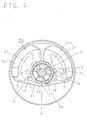
- FIG. 1 shows major portions of a flat type coreless vibrator motor having an eccentric rotor.
- Reference numeral 1 denotes an eccentric commutator base member made of a printed wiring circuit board which is shaped as an expanded fan when the planar surface thereof is viewed from above and has a shaft installation hole 1a formed at the centre thereof.
- highly slippery resin 2 exhibiting high density and a specific gravity of 6 is integrally and thinly formed on the entire surface of the fan-shaped eccentric commutator base member 1, so as to form an eccentric commutator SS.
- Six printed wiring segment patterns 1s having slits which are inclined form the radial direction for preventing sparking, are arranged at the eccentric commutator base member 1.
- An armature coil end connection terminal 1b protrudes from the semicircular arc shaped bottom portion of three segment patterns at the movement of the centre of mass.
- the eccentric commutator base member 1 is installed, by being extended with a reinforced portion 1c, to the inside of both ends 2a of a half-circle of which both ends are formed of high density highly slippery resin 2.
- Each of the segment patterns 1s are electrically connected to the segment patten on the opposite side of the shaft by a pattern on the surface and a through-hole 1A.
- a resin bearing holder 2a ascends from the high density highly slippery resin 2 toward the opposite segment pattern in the shaft installation hole 1a at the centre of the eccentric commutator base member 1.
- a bearing portion 2b is formed at the centre of the eccentric commutator base member 1 and is maintained at the eccentric commutator base member 1 by a dam portion 2c protruding toward the segment pattern from the high density, highly slippery resin 2.
- an arc shaped portion 2d which becomes a portion of an eccentric weight for the movement of the centre of mass is installed at the semicircular outer circumferential portion.
- Air-core armature coil position determination fixing guides 2e are integrally formed with the high density, highly slippery resin 2, as indicated by a dotted line, at the inside surface of each of the six segment patterns 1s at an arranged open angle of 120°.
- the air-core armature coils 3 made of a winding around a self-fusing line are inserted in the air-core armature coil position determination fixing guides 2e and the beginning and termination end portions of the winding are wound around the armature coil end connection terminal 1b, and dip-soldered thereto, through a predetermined groove so as to not protrude above the thickness of the rotor, thus forming an eccentric rotor R2.
- a flat, circular magnet 4 for driving the rotor has north (N) and south (S) poles which are alternately positioned in four quadrants.
- FIG. 2 shows a cross sectional view of the vibrator motor of FIG. 1 in which a modified eccentric rotor is used; and
- FIG. 3 shows a vertical sectional view of the vibrator motor shown in FIG. 2.
- the eccentric commutator base member 11 is formed to be a sector slightly greater than a semicircle and the armature coil end connection terminals 1f is installed opposite to the eccentric commutator base members 11 with respect to the centre of mass, unlike the above embodiment.
- a notch f for hooking is formed at each of the armature coil end connection terminals If.
- the armature coil end connection terminal 1f is disposed so as not to overlap the air-core armature coils 3, when the planar surface thereof is viewed from above so that the connection to the end portion is made easy.
- a resin bearing holder 2a lifted from the semicircular high density, highly slippery resin 2 is installed by being extended toward the opposite position of the segment pattern, and a bearing portion 2b is formed at the centre thereof.
- a dam portion 2c formed of the high density, highly slippery resin 2 protrudes toward the segment pattern.
- the second dam portion 2cc for reinforcement is installed further toward the segment pattern at the part of the resin bearing holder 2a via the through-hole 1A.
- Each of the dam portions 2c and 2cc is molded to prevent the resin from flowing the slits between each segment 1s.
- the air-core armature coils 3 made of a winding around a self-fusing line are inserted in the air-core armature coil position determination fixing guides 2e and the beginning and termination end portions of the winding are soldered to the armature coil end connection terminal 1f, so as not to protrude above the thickness of the rotor, thus forming an eccentric rotor R3.
- the air-core armature coil position determination fixing guides 2e, which fix the air-core armature coils 3 in place, are deformed by heating and fused, or are fixed by a reflow of powder or solid epoxy.
- the motor including the eccentric rotor R3 is an axial direction gap type motor and is driven by the flat, circular magnet 4.
- Reference numeral 5 of FIG. 3 denotes a bracket made of a tin-plated steel plate for maintaining the magnet 4 and concurrently providing a magnetic path.
- the bracket 5 forms a housing with a case 6.
- a shaft J is rotatably installed through the bearing portion 2b of the resin bearing holder 2a.
- a pair of brushes 7 disposed at the bracket 5 sliding-contact the segment pattern at an open angle of 90° so that power is supplied to the armature coils 3 from the outside via a flexible substrate 8.
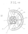
- FIGS. 4A and 4B show a modified shape of the second preferred embodiment shown in FIG. 2, in which FIG. 4A is a cross sectional view of one side of the commutator and FIG. 4B is a cross sectional view of the other side of the commutator.
- reference numeral 111 denotes a fan-shaped printed wiring commutator device and six segments 1s, surfaces of which are plated with a noble metal and having inclined slits, are arranged on one side thereof for spark prevention.
- a conductive body for electrically connecting the segments opposite to each other among the above segments is formed at an inner surface via a through-hole 1A.
- Reference numerals 1h, 1i, 1j and 1k denote resin passing portion which are one of the features of the present invention.
- the resin passing portion are reinforced when a resin holder, an air-core coil position determination guide, an eccentric weight which will be described later are integrally formed with the printed wiring commutator base member 11.
- the resin passing portions 1h and 1i are installed at the air-core coil position determination guide, the resin passing portions 1j and 1k formed by notching a part of the outer circumference are installed at the eccentric weight, and the through-hole 1B is installed at the resin bearing holder 2a.
- a sliding portion 2h where the bearing portion 2b and an oil storing groove rotatably installed at a shaft (which will be described later) are coaxially installed, is arranged at the resin bearing holder 2a, and passes through the through-hole 1A by leg portions which are arranged to be well balanced.
- the second dam portion 2cc at the surface and the first dam portion 2c at the central portion are reinforced by being coated with resin.
- Part 2f of the eccentric weight lifts the arc-shaped portion 2d of the eccentric weight toward the segment through the resin passing portion 1j. Both ends of the arc-shaped portion 2d of the eccentric weight are tapered to prevent loss of wind during rotation.
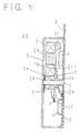
- FIG. 5 shows a flat coreless vibrator motor using the eccentric rotor R3.
- the bearing portion 2b has a recess c of a few microns formed inside, loss of bearing is reduced.
- the middle portion of the resin holder 2a is thicker than other portions as shown in the drawing so that a recess can be easily formed using the difference in percentage of contraction of resin.
- the few-micron recess can be fabricated by excessive drawing with a mold pin.
- the air-core coil position determination guide, the air-core armature coil 3 and the eccentric weight can be formed together with the single resin injection molding according to the above method.
- the structure is simplified and the cost is lowered.
- the air-core coils 3 can be directly installed at the printed wiring commutator base member 11, a gap can be made small and efficiency is increased.
- the resin bearing holder 22a is formed of low density sliding resin and then the air-core coil position determination guides 2e and the eccentric weight portion is molded with a high density resin.
- a sintered oilless bearing can be used instead of the resin bearing holder 22a.
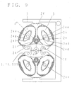
- FIGS. 7, 8, 9 and 10 show a basic method of manufacturing an eccentric rotor having the above eccentric printed wiring commutator base member.
- FIGS. 7, 8 and 10 are bottom views and FIG. 9 is a plan view. That is, eccentric printed wiring commutator base members 1, 11 and 111 are integrally connected by the connection portions 1g at the same pitch for mass production and are manufactured using press.
- the printed wiring commutator base member 11 manufactured in the above method, as shown in FIGS. 8, 9 and 10, is set to an injection mold installed by being connected plurally at the same pitch.
- the resin holder 2a, the two air-core coil position determination guides 2e, and the part 2f of the eccentric weight connected to the resin bearing holder 2a are installed at the opposite side of the segment.
- the bearing portion 2b in which the shaft J is rotatably installed, at which will be described later, and the sliding portion 2h where the oil storing groove is coaxially installed are arranged at the resin holder 2a.
- the part 2f of the eccentric weight lifts the arc-shaped portion 2d of the eccentric weight toward the segment through the resin passing portion 1j. Both ends of the other part 2d of the eccentric weight are tapered like the above leg shape to prevent loss of wind during rotation.
- the air-core armature coils 3 are inserted in the air-core armature coil position determination guides 2e and the ends of a winding are hooked and soldered on notches f of the three air-core coil end connection terminals 1f, thus forming the eccentric rotor.
- r denotes a printed resistor for preventing spark.
- a head portion 2ee of the air-core armature coil position determination guide 2e is pressed and heated by a wedge-shaped jig, or powdered epoxy is heated and cured or fixed in a reflow manner using an ultraviolet curing type adhesive.
- a head portion 2ee of the air-core armature coil position determination guide 2e is pressed and heated by a wedge-shaped jig, or powdered epoxy is heated and cured or fixed in a reflow manner using an ultraviolet curing type adhesive.
- FIGS. 11 and 12 show an eccentric rotor according to the fourth preferred embodiment of the present invention.
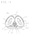
- reference numeral 12 denotes an eccentric printed wiring commutator base member formed to be an expanded fan shape when the planar surface thereof viewed from above, in which a shaft installation hole 1a is formed at the centre thereof at the same time as the six segments 1s of which surfaces are plated with the noble metal and having inclined slits installed at one side thereof for spark prevention.
- Part C3 of the armature coil is print-wired above the segments 1s
- part C4 of the armature coil is print-wired on the other side of the eccentric printed wiring commutator 12, and the parts C3 and C4 are connected in series through the through-hole 1B to form a single armature coil.
- the resin passing portions 1h, 1k and 1n which are characteristic features of the present invention, are reinforced when the resin bearing holder, the air-core coil position determination resin guide, and the resin eccentric weight are integrally formed with the printed wiring commutator base member 11 as described above.
- the resin passing portion 1h is hooked by the air-core coil position determination.
- resin guide and the resin eccentric weight, the slit 1n and the resin passing portion 1k formed by notching part of the outer circumference are hooked by the resin eccentric weight, and the through-hole 1A is hooked by the resin bearing holder.
- reference numeral 2ef denotes a space for drawing the end portion of the air-core armature coils 3.
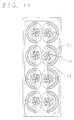
- a plurality of printed wiring commutator base members 12, which have the above structure and are connected with the same pitch, are set to an injection mold, as shown in FIG. 10.
- FIG. 14 by outset molding using resin of about specific gravity 4-5 and moving friction coefficient of 0.3, the resin holder 2a, the two air-core coil position determination guides 2e, and the part 2f of the eccentric weight connected to the resin bearing holder 2a are installed at the opposite side of the segment.
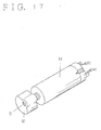
- the axial direction gap type coreless vibrator motor using the above eccentric rotor R5 is assembled as shown in FIG. 15.
- an insulated copper wire 9 is embedded in the eccentric weight.
- the insulated copper wire 9 is coated with polyurethane except for cut-away portions of both ends thereof and formed to be arc-shaped so as not to be shorted by the printed wiring armature coil located inside. As a result, the position of the centre of mass can be moved much further so that vibrations become greater.
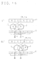
- Anti-torque preventing rotation is not generated at other positions. Thus, as long as the power is supplied, the rotation continues cyclically. As two armatures are always electrically connected in three three-phase armatures, torque is improved compared to two three-phase armatures where one armature is open.
- part of a copper pattern portion which is a boundary with the resin portion is made wider by molding so as not to be shorted.
Landscapes
- Engineering & Computer Science (AREA)
- Power Engineering (AREA)
- Dc Machiner (AREA)
- Apparatuses For Generation Of Mechanical Vibrations (AREA)
- Connection Of Motors, Electrical Generators, Mechanical Devices, And The Like (AREA)
- Motor Or Generator Current Collectors (AREA)
Applications Claiming Priority (11)
| Application Number | Priority Date | Filing Date | Title |
|---|---|---|---|
| JP6827099 | 1999-03-15 | ||
| JP06827099A JP3314160B2 (ja) | 1999-03-15 | 1999-03-15 | 偏心整流子と同整流子の製法及び同整流子を用いた扁平コアレス振動モータ |
| JP9302099 | 1999-03-31 | ||
| JP09302099A JP3627906B2 (ja) | 1999-03-31 | 1999-03-31 | 樹脂軸受部を備えた整流子と同整流子を用いた軸固定型モータ |
| JP15449899A JP3299728B2 (ja) | 1999-06-02 | 1999-06-02 | 印刷配線コミュテータ部材を備えた扁平ロータと同ロータを用いた扁平コアレスモータ |
| JP15449899 | 1999-06-02 | ||
| JP20159699A JP3301993B2 (ja) | 1999-07-15 | 1999-07-15 | 印刷配線コミュテータ部材を有する非モールド型偏心ロータ |
| JP20159699 | 1999-07-15 | ||
| JP25108699 | 1999-09-06 | ||
| JP25108699 | 1999-09-06 | ||
| EP99310641A EP1037362B1 (fr) | 1999-03-15 | 1999-12-30 | Rotor eccentrique |
Related Parent Applications (1)
| Application Number | Title | Priority Date | Filing Date |
|---|---|---|---|
| EP99310641A Division EP1037362B1 (fr) | 1999-03-15 | 1999-12-30 | Rotor eccentrique |
Publications (2)
| Publication Number | Publication Date |
|---|---|
| EP1467467A2 true EP1467467A2 (fr) | 2004-10-13 |
| EP1467467A3 EP1467467A3 (fr) | 2005-12-28 |
Family
ID=27524096
Family Applications (2)
| Application Number | Title | Priority Date | Filing Date |
|---|---|---|---|
| EP04076198A Withdrawn EP1467467A3 (fr) | 1999-03-15 | 1999-12-30 | Rotor eccentrique |
| EP99310641A Expired - Lifetime EP1037362B1 (fr) | 1999-03-15 | 1999-12-30 | Rotor eccentrique |
Family Applications After (1)
| Application Number | Title | Priority Date | Filing Date |
|---|---|---|---|
| EP99310641A Expired - Lifetime EP1037362B1 (fr) | 1999-03-15 | 1999-12-30 | Rotor eccentrique |
Country Status (5)
| Country | Link |
|---|---|
| EP (2) | EP1467467A3 (fr) |
| KR (1) | KR100297337B1 (fr) |
| CN (1) | CN1092410C (fr) |
| DE (1) | DE69920165T2 (fr) |
| SG (1) | SG75999A1 (fr) |
Families Citing this family (12)
| Publication number | Priority date | Publication date | Assignee | Title |
|---|---|---|---|---|
| US20040222708A1 (en) * | 1998-11-13 | 2004-11-11 | Barry Reginald Hobson | Electric oscillatory machine |
| KR20020001108A (ko) * | 2000-06-26 | 2002-01-09 | 이형도 | 휴대폰용 진동 모터의 회전자 |
| KR20030038979A (ko) * | 2001-11-09 | 2003-05-17 | 자화전자 주식회사 | 편평형 코아레스 진동모터 |
| KR20030039437A (ko) * | 2001-11-13 | 2003-05-22 | 엘지이노텍 주식회사 | 편평형 진동모터의 부등각 정류자 구조 |
| JP3645221B2 (ja) * | 2002-01-21 | 2005-05-11 | 東京パーツ工業株式会社 | 偏心ロータと同ロータを備えた扁平型振動モータ |
| KR100512300B1 (ko) * | 2002-03-25 | 2005-09-02 | 삼성전기주식회사 | 코인타입 진동모터 |
| KR100719811B1 (ko) * | 2005-09-09 | 2007-05-21 | 삼성전기주식회사 | 로터, 이를 구비한 진동 모터 및 로터의 제작방법 |
| JP2010200513A (ja) * | 2009-02-26 | 2010-09-09 | Shicoh Engineering Co Ltd | 軸方向空隙型コアレス振動モータ及び無線通信装置 |
| EP3925061A1 (fr) * | 2019-02-12 | 2021-12-22 | Valeo Equipements Electriques Moteur | Machine électrique synchrone polyphasée à commutateur mécanique |
| FR3092712A1 (fr) * | 2019-02-12 | 2020-08-14 | Valeo Equipements Electriques Moteur | Machine électrique synchrone polyphasée à commutateur mécanique |
| CN115104837B (zh) * | 2022-06-14 | 2024-07-19 | 山西立讯精密工业有限公司 | 电动刷子 |
| CN115800653A (zh) * | 2022-11-23 | 2023-03-14 | 肇庆晟辉电子科技有限公司 | 一种散热扇的定子组件的生产线及制造方法 |
Family Cites Families (8)
| Publication number | Priority date | Publication date | Assignee | Title |
|---|---|---|---|---|
| JPH03169249A (ja) * | 1989-11-27 | 1991-07-22 | Asahi Chem Ind Co Ltd | コアレスモータ用回転子 |
| JP3179669B2 (ja) * | 1994-11-30 | 2001-06-25 | 東京パーツ工業株式会社 | 偏平コアレスモータのロータ |
| JP3502697B2 (ja) * | 1995-05-30 | 2004-03-02 | 東京パーツ工業株式会社 | 偏平コアレスモータのロータ |
| JP3342250B2 (ja) * | 1995-07-14 | 2002-11-05 | 東京パーツ工業株式会社 | 扁平コアレス振動モータのロータとその製造方法 |
| JP3380388B2 (ja) * | 1996-01-30 | 2003-02-24 | 東京パーツ工業株式会社 | 軸固定型モータ |
| JPH09322504A (ja) * | 1996-05-30 | 1997-12-12 | Sankyo Seiki Mfg Co Ltd | 小型モータ |
| JPH1023708A (ja) * | 1996-07-01 | 1998-01-23 | Sankyo Seiki Mfg Co Ltd | 振動モータ |
| JP3431799B2 (ja) * | 1997-02-27 | 2003-07-28 | 東京パーツ工業株式会社 | 印刷配線板を備えた扁平コアレスモータのロータ |
-
1999
- 1999-12-23 CN CN99124972A patent/CN1092410C/zh not_active Expired - Fee Related
- 1999-12-24 KR KR1019990061906A patent/KR100297337B1/ko not_active Expired - Fee Related
- 1999-12-30 DE DE69920165T patent/DE69920165T2/de not_active Expired - Fee Related
- 1999-12-30 EP EP04076198A patent/EP1467467A3/fr not_active Withdrawn
- 1999-12-30 EP EP99310641A patent/EP1037362B1/fr not_active Expired - Lifetime
- 1999-12-30 SG SG1999006668A patent/SG75999A1/en unknown
Also Published As
| Publication number | Publication date |
|---|---|
| KR100297337B1 (ko) | 2001-10-22 |
| EP1467467A3 (fr) | 2005-12-28 |
| SG75999A1 (en) | 2000-10-24 |
| DE69920165T2 (de) | 2005-09-22 |
| DE69920165D1 (de) | 2004-10-21 |
| CN1256533A (zh) | 2000-06-14 |
| CN1092410C (zh) | 2002-10-09 |
| EP1037362B1 (fr) | 2004-09-15 |
| KR20000012780A (ko) | 2000-03-06 |
| EP1037362A2 (fr) | 2000-09-20 |
| EP1037362A3 (fr) | 2001-08-16 |
Similar Documents
| Publication | Publication Date | Title |
|---|---|---|
| US6384499B2 (en) | Eccentric rotor and compact vibrator motor including the eccentric rotor | |
| CA2340957C (fr) | Moteur a vibration sans balai a courant continu | |
| US6713911B2 (en) | Disc-shaped eccentric rotor and flat type vibrator motor having the rotor | |
| US6674202B2 (en) | Eccentric commutator for vibrator motor | |
| EP1037362B1 (fr) | Rotor eccentrique | |
| US6765331B2 (en) | Eccentric rotor having high density member, manufacturing method thereof, and flat coreless vibrator motor using the eccentric rotor | |
| JP3322954B2 (ja) | 小型モータの組立式整流子 | |
| US20010011849A1 (en) | Non-circular, flat motor and manufacturing method thereof | |
| JP3560601B1 (ja) | モールド型偏心ロータと同ロータを備えた軸方向空隙型コアレス振動モータ | |
| JPH08256449A (ja) | 出力軸のない振動モータ | |
| CN1052825C (zh) | 用于便携式设备和信息发送装置的微型电动机、微型振动电动机 | |
| US20010040412A1 (en) | Radial gap, rotary yoke type brushless vibration motor | |
| JP2001104882A (ja) | 扁平型振動モータ | |
| KR20040024442A (ko) | 초 슬림형 코어리스 모터 | |
| JP3759092B2 (ja) | 偏心ロータと同ロータを備えた扁平コアレス振動モータ | |
| KR100797279B1 (ko) | Dc 무브러시 진동 모터 | |
| KR100220648B1 (ko) | 이동 통신용 초소형 진동 발생기 | |
| JP3572484B2 (ja) | 高密度部材を備えた偏心ロータと同ロータの製法及び同ロータを用いた扁平コアレス振動モータ | |
| JP3493352B2 (ja) | 高密度部材を有する偏心ロータと同ロータの製法及び同ロータを用いた扁平コアレス振動モータ | |
| JP3357333B2 (ja) | 偏心ロータと同偏心ロータを用いた小型振動モータ | |
| JP2001321723A (ja) | 扁平型振動モータ | |
| JP2002224621A (ja) | マイクロ扁平振動モータの最適化構造 | |
| KR19990031553U (ko) | 전동기의 하우징 및 전원연결장치 | |
| KR20020088440A (ko) | 진동모터 | |
| JP2002177885A (ja) | 扁平型振動モータ |
Legal Events
| Date | Code | Title | Description |
|---|---|---|---|
| PUAI | Public reference made under article 153(3) epc to a published international application that has entered the european phase |
Free format text: ORIGINAL CODE: 0009012 |
|
| AC | Divisional application: reference to earlier application |
Ref document number: 1037362 Country of ref document: EP Kind code of ref document: P |
|
| AK | Designated contracting states |
Kind code of ref document: A2 Designated state(s): DE FR GB |
|
| PUAL | Search report despatched |
Free format text: ORIGINAL CODE: 0009013 |
|
| AK | Designated contracting states |
Kind code of ref document: A3 Designated state(s): DE FR GB |
|
| RIC1 | Information provided on ipc code assigned before grant |
Ipc: 7B 06B 1/16 B Ipc: 7G 08B 6/00 B Ipc: 7H 02K 7/06 A |
|
| 17P | Request for examination filed |
Effective date: 20060623 |
|
| AKX | Designation fees paid |
Designated state(s): DE FR GB |
|
| STAA | Information on the status of an ep patent application or granted ep patent |
Free format text: STATUS: THE APPLICATION IS DEEMED TO BE WITHDRAWN |
|
| 18D | Application deemed to be withdrawn |
Effective date: 20090702 |