EP1467475A2 - Netzbrückensteuerung für einen Frequenzwandler - Google Patents
Netzbrückensteuerung für einen Frequenzwandler Download PDFInfo
- Publication number
- EP1467475A2 EP1467475A2 EP04076040A EP04076040A EP1467475A2 EP 1467475 A2 EP1467475 A2 EP 1467475A2 EP 04076040 A EP04076040 A EP 04076040A EP 04076040 A EP04076040 A EP 04076040A EP 1467475 A2 EP1467475 A2 EP 1467475A2
- Authority
- EP
- European Patent Office
- Prior art keywords
- bridge
- controlled
- mains bridge
- mains
- conducting
- Prior art date
- Legal status (The legal status is an assumption and is not a legal conclusion. Google has not performed a legal analysis and makes no representation as to the accuracy of the status listed.)
- Granted
Links
Images

Classifications
-
- H—ELECTRICITY
- H02—GENERATION; CONVERSION OR DISTRIBUTION OF ELECTRIC POWER
- H02M—APPARATUS FOR CONVERSION BETWEEN AC AND AC, BETWEEN AC AND DC, OR BETWEEN DC AND DC, AND FOR USE WITH MAINS OR SIMILAR POWER SUPPLY SYSTEMS; CONVERSION OF DC OR AC INPUT POWER INTO SURGE OUTPUT POWER; CONTROL OR REGULATION THEREOF
- H02M5/00—Conversion of AC power input into AC power output, e.g. for change of voltage, for change of frequency, for change of number of phases
- H02M5/40—Conversion of AC power input into AC power output, e.g. for change of voltage, for change of frequency, for change of number of phases with intermediate conversion into DC
- H02M5/42—Conversion of AC power input into AC power output, e.g. for change of voltage, for change of frequency, for change of number of phases with intermediate conversion into DC by static converters
- H02M5/44—Conversion of AC power input into AC power output, e.g. for change of voltage, for change of frequency, for change of number of phases with intermediate conversion into DC by static converters using discharge tubes or semiconductor devices to convert the intermediate DC into AC
- H02M5/453—Conversion of AC power input into AC power output, e.g. for change of voltage, for change of frequency, for change of number of phases with intermediate conversion into DC by static converters using discharge tubes or semiconductor devices to convert the intermediate DC into AC using devices of a triode or transistor type requiring continuous application of a control signal
- H02M5/458—Conversion of AC power input into AC power output, e.g. for change of voltage, for change of frequency, for change of number of phases with intermediate conversion into DC by static converters using discharge tubes or semiconductor devices to convert the intermediate DC into AC using devices of a triode or transistor type requiring continuous application of a control signal using semiconductor devices only
- H02M5/4585—Conversion of AC power input into AC power output, e.g. for change of voltage, for change of frequency, for change of number of phases with intermediate conversion into DC by static converters using discharge tubes or semiconductor devices to convert the intermediate DC into AC using devices of a triode or transistor type requiring continuous application of a control signal using semiconductor devices only having a rectifier with controlled elements
-
- H—ELECTRICITY
- H02—GENERATION; CONVERSION OR DISTRIBUTION OF ELECTRIC POWER
- H02M—APPARATUS FOR CONVERSION BETWEEN AC AND AC, BETWEEN AC AND DC, OR BETWEEN DC AND DC, AND FOR USE WITH MAINS OR SIMILAR POWER SUPPLY SYSTEMS; CONVERSION OF DC OR AC INPUT POWER INTO SURGE OUTPUT POWER; CONTROL OR REGULATION THEREOF
- H02M7/00—Conversion of AC power input into DC power output; Conversion of DC power input into AC power output
- H02M7/02—Conversion of AC power input into DC power output without possibility of reversal
- H02M7/04—Conversion of AC power input into DC power output without possibility of reversal by static converters
- H02M7/12—Conversion of AC power input into DC power output without possibility of reversal by static converters using discharge tubes with control electrode or semiconductor devices with control electrode
- H02M7/21—Conversion of AC power input into DC power output without possibility of reversal by static converters using discharge tubes with control electrode or semiconductor devices with control electrode using devices of a triode or transistor type requiring continuous application of a control signal
- H02M7/217—Conversion of AC power input into DC power output without possibility of reversal by static converters using discharge tubes with control electrode or semiconductor devices with control electrode using devices of a triode or transistor type requiring continuous application of a control signal using semiconductor devices only
- H02M7/219—Conversion of AC power input into DC power output without possibility of reversal by static converters using discharge tubes with control electrode or semiconductor devices with control electrode using devices of a triode or transistor type requiring continuous application of a control signal using semiconductor devices only in a bridge configuration
Definitions
- the present invention relates to control of the mains bridge of a frequency converter in a braking situation where power is flowing in the direction towards the supply network.
- the invention relates to a method for controlling the mains bridge of a PWM-type frequency converter, like the one known e.g. from Finnish patent FI 108819 which is able to function in all four quadrants of the power - rotational speed coordinate axes, in a braking situation where power is flowing in the direction towards the supply network, and to a four-quadrant PWM-frequency converter.
- the method of the invention for controlling the mains bridge is also directly applicable in prior-art PWM-frequency converters having an intermediate circuit capacitor rated for use as an energy storage.
- Voltage-controlled PWM-frequency converters have a mains bndge for rectification of the alternating voltage of the supply network to produce an intermediate circuit d.c. voltage and a load bridge for inversion of the intermediate-circuit direct voltage to produce a variable-frequency alternating voltage when power is flowing from the network towards the load.
- the frequency converter feeds a three-phase load, such as a cage induction motor, which can be used in many applications, for example in pumps and fans.
- the load bridge is a full-wave bridge provided with PWM-controlled semiconductor switches and diodes connected in inverse-parallel with these.
- the load bridge may be a controlled full-wave bridge, in which case it is provided with controlled semiconductor switches, such as IGBT, and diodes connected in inverse-parallel with them.
- controlled semiconductor switches such as IGBT
- diodes connected in inverse-parallel with them.
- power may flow from network to load or also from load to network e.g. in situations where the motor is being braked.
- a specific function of the mains bridge is to ensure that the intermediate circuit current has an unobstructed flow path to the supply network regardless of the direction of the current.
- the existence of a current flow path is ensured by controlling the mains bridge semiconductor switches in a manner such that the controlled semiconductor switch in the upper branch of the phase having the highest supply voltage instantaneous value and the controlled semiconductor switch in the lower branch of the phase having the lowest supply voltage instantaneous value are conducting through 120° at a time.
- control of the mains bridge and the ratings of the main components should be designed with an aim to prevent excessive distortion of the voltage at the coupling point of the frequency converter.
- the supply voltage is distorted especially in the commutation situation.
- the intermediate circuit current is positive, i.e. when power is flowing towards the motor, the mains bridge current flows exclusively through the shunt diodes.
- a small commutation notch appears in the coupling point voltage as the two phases are conducting simultaneously and a larger notch of a shorter duration appears as the reverse current of the diode being turned off is interrupted and possibly transferred for an instant even to the diode of the opposite branch.
- the voltage notch appearing at the coupling point can be reduced e.g. by connecting small capacitors or RC protectors between the phases of the mains bridge.
- the object of the present invention is to overcome the drawbacks of prior art and achieve a new type of control arrangement that is especially applicable for the control of the mains bridge of a four-quadrant frequency converter.
- the commutation notch appearing in a braking situation can be eliminated or significantly diminished by turning the conducting phase current positive just before commutation. This is achieved by advancing the control of the IGBT the more the larger is the negative current in the braking situation.
- Fig. 1 presents a three-phase voltage-controlled PWM-frequency converter provided with an AC inductor 9 for limiting supply network harmonics, a mains bridge 10 for rectification of three-phase supply voltage consisting of phase voltages U U , U V , U W to produce an intermediate-circuit DC voltage U DC , an intermediate circuit capacitor 14, which may function either as an energy storage or as a limiter of voltage spikes, and a load bridge (inverter) 11 for inversion of the direct voltage of the DC intermediate circuit to produce a variable-frequency three-phase alternating voltage consisting of phase voltages U R , U S , U T .
- the frequency converter feeds a three-phase cage induction motor (M) 12.
- the load bridge 11 is a full-wave bridge with a control unit 13 controlling by pulse width modulation the semiconductor switches of each phase, which are connected in inverse-parallel with shunt diodes.
- the mains bridge 10 is a controlled full-wave bridge in which power may flow in the direction from mains to load and also for load to mains e.g. when the motor is being braked.
- Each branch of the mains bridge 10 contains controllable semiconductor switches V1-V6, such as IGBTs, and diodes (shunt diodes) D1-D6 connected in inverse-parallel with them.
- V1-V6 controllable semiconductor switches
- D1-D6 diodes (shunt diodes)
- the mains bridge 10 is controlled in a manner such that the IGBT in the upper branch of the phase having the highest instantaneous voltage value is conducting and the IGBT in the lower branch of the phase with the lowest instantaneous voltage value is conducting. In other words, the IGBTs are held in the conducting state if the diodes in parallel with them are conducting when the power is flowing towards the motor.
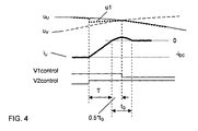
- the occurrence of a commutation notch in a braking situation can be prevented by turning the conducting phase current positive just before commutation. This is accomplished by advancing the control of the IGBT the more the larger is the negative current in a braking situation.
- the IGBT to be conducting next is turned on before the firing instant determined by the normal 120° firing rule, with an anticipation sufficient to cause the direction of the conducting phase current to be turned from the IGBT to the shunt diode before the control signal to the previously conducting IGBT is interrupted.
- the control signals to the IGBTs overlap by the anticipation T. In the above-described example situation, this means what follows (figures 3a and 3b):
Landscapes
- Engineering & Computer Science (AREA)
- Power Engineering (AREA)
- Rectifiers (AREA)
- Inverter Devices (AREA)
- General Induction Heating (AREA)
- Ac-Ac Conversion (AREA)
- Control Of Motors That Do Not Use Commutators (AREA)
- Dc-Dc Converters (AREA)
- Noise Elimination (AREA)
- Control Of Eletrric Generators (AREA)
- Channel Selection Circuits, Automatic Tuning Circuits (AREA)
- Stabilization Of Oscillater, Synchronisation, Frequency Synthesizers (AREA)
Applications Claiming Priority (2)
| Application Number | Priority Date | Filing Date | Title |
|---|---|---|---|
| FI20030552 | 2003-04-11 | ||
| FI20030552A FI114760B (fi) | 2003-04-11 | 2003-04-11 | Taajuusmuuttajan verkkosillan ohjaus |
Publications (3)
| Publication Number | Publication Date |
|---|---|
| EP1467475A2 true EP1467475A2 (de) | 2004-10-13 |
| EP1467475A3 EP1467475A3 (de) | 2007-01-03 |
| EP1467475B1 EP1467475B1 (de) | 2010-08-04 |
Family
ID=8565956
Family Applications (1)
| Application Number | Title | Priority Date | Filing Date |
|---|---|---|---|
| EP04076040A Expired - Lifetime EP1467475B1 (de) | 2003-04-11 | 2004-03-31 | Netzbrückensteuerung für einen Frequenzwandler |
Country Status (6)
| Country | Link |
|---|---|
| US (1) | US7102333B2 (de) |
| EP (1) | EP1467475B1 (de) |
| AT (1) | ATE476781T1 (de) |
| DE (1) | DE602004028428D1 (de) |
| DK (1) | DK1467475T3 (de) |
| FI (1) | FI114760B (de) |
Cited By (2)
| Publication number | Priority date | Publication date | Assignee | Title |
|---|---|---|---|---|
| CN104617796A (zh) * | 2015-03-06 | 2015-05-13 | 南京南瑞继保电气有限公司 | 一种模块化的ac/dc变换器及换流器拓扑 |
| CN105406730A (zh) * | 2015-11-10 | 2016-03-16 | 深圳市英威腾电气股份有限公司 | 一种四象限igbt封装模块和拓扑装置 |
Families Citing this family (3)
| Publication number | Priority date | Publication date | Assignee | Title |
|---|---|---|---|---|
| JP5776496B2 (ja) * | 2011-10-31 | 2015-09-09 | 富士電機株式会社 | 電力変換装置 |
| CN104218820A (zh) * | 2014-08-15 | 2014-12-17 | 广州日滨科技发展有限公司 | 四象限变频器 |
| US9385638B2 (en) | 2014-10-30 | 2016-07-05 | Eaton Corporation | Regenerative rectifier for a motor control drive |
Family Cites Families (10)
| Publication number | Priority date | Publication date | Assignee | Title |
|---|---|---|---|---|
| US4447868A (en) | 1982-04-05 | 1984-05-08 | General Electric Company | Regenerative rectifier circuit |
| US4449176A (en) * | 1982-05-26 | 1984-05-15 | General Electric Company | Single phase regeneration with a polyphase rectification power circuit |
| JPS62104481A (ja) * | 1985-10-31 | 1987-05-14 | Yaskawa Electric Mfg Co Ltd | 直流電源装置の駆動方式 |
| US4928052A (en) * | 1987-04-30 | 1990-05-22 | Fanuc Ltd. | Power supply regenerating circuit |
| US5256949A (en) * | 1989-05-23 | 1993-10-26 | Thor Technology Corporation | AC power line current regeneration |
| JP3049156B2 (ja) | 1992-08-06 | 2000-06-05 | ファナック株式会社 | 電源回生装置 |
| JP3232689B2 (ja) * | 1992-09-30 | 2001-11-26 | 株式会社明電舎 | 電源回生装置の制御方式 |
| JPH06327291A (ja) * | 1993-05-11 | 1994-11-25 | Fanuc Ltd | 回生電流帰還制御方法 |
| US5621627A (en) * | 1995-04-14 | 1997-04-15 | Ac International Inc. | A.C. to A.C. power converter for the adaptive correction of waveform abnormalities |
| US6166513A (en) * | 1999-04-09 | 2000-12-26 | Robicon Corporation | Four-quadrant AC-AC drive and method |
-
2003
- 2003-04-11 FI FI20030552A patent/FI114760B/fi not_active IP Right Cessation
-
2004
- 2004-03-31 EP EP04076040A patent/EP1467475B1/de not_active Expired - Lifetime
- 2004-03-31 DE DE602004028428T patent/DE602004028428D1/de not_active Expired - Lifetime
- 2004-03-31 DK DK04076040.7T patent/DK1467475T3/da active
- 2004-03-31 AT AT04076040T patent/ATE476781T1/de not_active IP Right Cessation
- 2004-04-08 US US10/820,101 patent/US7102333B2/en not_active Expired - Lifetime
Cited By (3)
| Publication number | Priority date | Publication date | Assignee | Title |
|---|---|---|---|---|
| CN104617796A (zh) * | 2015-03-06 | 2015-05-13 | 南京南瑞继保电气有限公司 | 一种模块化的ac/dc变换器及换流器拓扑 |
| CN105406730A (zh) * | 2015-11-10 | 2016-03-16 | 深圳市英威腾电气股份有限公司 | 一种四象限igbt封装模块和拓扑装置 |
| CN105406730B (zh) * | 2015-11-10 | 2018-09-14 | 深圳市英威腾电气股份有限公司 | 一种四象限igbt封装模块和拓扑装置 |
Also Published As
| Publication number | Publication date |
|---|---|
| FI20030552L (fi) | 2004-10-12 |
| DK1467475T3 (da) | 2010-11-08 |
| EP1467475B1 (de) | 2010-08-04 |
| FI20030552A0 (fi) | 2003-04-11 |
| FI114760B (fi) | 2004-12-15 |
| EP1467475A3 (de) | 2007-01-03 |
| US20040208033A1 (en) | 2004-10-21 |
| US7102333B2 (en) | 2006-09-05 |
| DE602004028428D1 (de) | 2010-09-16 |
| ATE476781T1 (de) | 2010-08-15 |
Similar Documents
| Publication | Publication Date | Title |
|---|---|---|
| US10090776B2 (en) | Method to protect a power converter arrangement and power converter arrangement with a protective device | |
| US6847531B2 (en) | System and method for regenerative PWM AC power conversion | |
| US6801441B2 (en) | Pulse width modulation frequency converter | |
| US6542390B2 (en) | System and method for regenerative PWM AC power conversion | |
| EP1998431A2 (de) | Doppelspannungswandlertopologie mit WYE-verbundener H-Brücke zur Betreibung eines elektrischen Hochgeschwindigkeitsmotors | |
| EP3855610B1 (de) | Verfahren und vorrichtung zur verminderung von überladung des dc-bus | |
| AU2005315333B2 (en) | Matrix converters | |
| US7102333B2 (en) | Control of the mains bridge of a frequency converter to regenerate energy from the motor to the supply | |
| CN111835215A (zh) | 转换器电路、电力转换系统以及电动机驱动装置 | |
| US9425702B2 (en) | System and method for safe switching in an AC-to-AC converter | |
| FI75699C (fi) | Stroemriktaranordning. | |
| JP2001069761A (ja) | パルス幅変調制御式コンバータ | |
| JP3873203B2 (ja) | 巻線型誘導機の速度制御装置及び方法 | |
| Raju | Regenerative and ride-through capability for AC drives through thyristor-based extensions of the diode front-end | |
| US20180097456A1 (en) | Circuit and method for multiphase operation of an electrical machine | |
| FI111201B (fi) | PWM-taajuusmuuttaja | |
| JPH0568305A (ja) | 交流電気車制御装置 | |
| Bose | 9.4 Converter Control of Machines | |
| Lee et al. | AC-DC Rectifiers | |
| JPH09233856A (ja) | 直流−交流変換器およびその制御装置 | |
| JP2000333363A (ja) | サージ保護回路 | |
| Nash | An investigation into current source inversion | |
| JPH07241081A (ja) | 電力変換装置 | |
| JPH06141555A (ja) | トランジスタ型インバータ駆動電動機 |
Legal Events
| Date | Code | Title | Description |
|---|---|---|---|
| PUAI | Public reference made under article 153(3) epc to a published international application that has entered the european phase |
Free format text: ORIGINAL CODE: 0009012 |
|
| AK | Designated contracting states |
Kind code of ref document: A2 Designated state(s): AT BE BG CH CY CZ DE DK EE ES FI FR GB GR HU IE IT LI LU MC NL PL PT RO SE SI SK TR |
|
| AX | Request for extension of the european patent |
Extension state: AL LT LV MK |
|
| PUAL | Search report despatched |
Free format text: ORIGINAL CODE: 0009013 |
|
| AK | Designated contracting states |
Kind code of ref document: A3 Designated state(s): AT BE BG CH CY CZ DE DK EE ES FI FR GB GR HU IE IT LI LU MC NL PL PT RO SE SI SK TR |
|
| AX | Request for extension of the european patent |
Extension state: AL LT LV MK |
|
| RIC1 | Information provided on ipc code assigned before grant |
Ipc: H02M 7/219 20060101ALI20061130BHEP Ipc: H02M 5/458 20060101AFI20040727BHEP |
|
| 17P | Request for examination filed |
Effective date: 20070208 |
|
| AKX | Designation fees paid |
Designated state(s): AT BE BG CH CY CZ DE DK EE ES FI FR GB GR HU IE IT LI LU MC NL PL PT RO SE SI SK TR |
|
| 17Q | First examination report despatched |
Effective date: 20090610 |
|
| GRAP | Despatch of communication of intention to grant a patent |
Free format text: ORIGINAL CODE: EPIDOSNIGR1 |
|
| GRAS | Grant fee paid |
Free format text: ORIGINAL CODE: EPIDOSNIGR3 |
|
| GRAA | (expected) grant |
Free format text: ORIGINAL CODE: 0009210 |
|
| AK | Designated contracting states |
Kind code of ref document: B1 Designated state(s): AT BE BG CH CY CZ DE DK EE ES FI FR GB GR HU IE IT LI LU MC NL PL PT RO SE SI SK TR |
|
| REG | Reference to a national code |
Ref country code: GB Ref legal event code: FG4D |
|
| REG | Reference to a national code |
Ref country code: CH Ref legal event code: EP |
|
| REG | Reference to a national code |
Ref country code: IE Ref legal event code: FG4D Ref country code: CH Ref legal event code: NV Representative=s name: KIRKER & CIE S.A. |
|
| REF | Corresponds to: |
Ref document number: 602004028428 Country of ref document: DE Date of ref document: 20100916 Kind code of ref document: P |
|
| REG | Reference to a national code |
Ref country code: DK Ref legal event code: T3 |
|
| REG | Reference to a national code |
Ref country code: NL Ref legal event code: VDEP Effective date: 20100804 |
|
| PG25 | Lapsed in a contracting state [announced via postgrant information from national office to epo] |
Ref country code: AT Free format text: LAPSE BECAUSE OF FAILURE TO SUBMIT A TRANSLATION OF THE DESCRIPTION OR TO PAY THE FEE WITHIN THE PRESCRIBED TIME-LIMIT Effective date: 20100804 Ref country code: FI Free format text: LAPSE BECAUSE OF FAILURE TO SUBMIT A TRANSLATION OF THE DESCRIPTION OR TO PAY THE FEE WITHIN THE PRESCRIBED TIME-LIMIT Effective date: 20100804 Ref country code: NL Free format text: LAPSE BECAUSE OF FAILURE TO SUBMIT A TRANSLATION OF THE DESCRIPTION OR TO PAY THE FEE WITHIN THE PRESCRIBED TIME-LIMIT Effective date: 20100804 |
|
| PG25 | Lapsed in a contracting state [announced via postgrant information from national office to epo] |
Ref country code: PL Free format text: LAPSE BECAUSE OF FAILURE TO SUBMIT A TRANSLATION OF THE DESCRIPTION OR TO PAY THE FEE WITHIN THE PRESCRIBED TIME-LIMIT Effective date: 20100804 Ref country code: SI Free format text: LAPSE BECAUSE OF FAILURE TO SUBMIT A TRANSLATION OF THE DESCRIPTION OR TO PAY THE FEE WITHIN THE PRESCRIBED TIME-LIMIT Effective date: 20100804 Ref country code: PT Free format text: LAPSE BECAUSE OF FAILURE TO SUBMIT A TRANSLATION OF THE DESCRIPTION OR TO PAY THE FEE WITHIN THE PRESCRIBED TIME-LIMIT Effective date: 20101206 Ref country code: BG Free format text: LAPSE BECAUSE OF FAILURE TO SUBMIT A TRANSLATION OF THE DESCRIPTION OR TO PAY THE FEE WITHIN THE PRESCRIBED TIME-LIMIT Effective date: 20101104 Ref country code: CY Free format text: LAPSE BECAUSE OF FAILURE TO SUBMIT A TRANSLATION OF THE DESCRIPTION OR TO PAY THE FEE WITHIN THE PRESCRIBED TIME-LIMIT Effective date: 20100804 |
|
| PG25 | Lapsed in a contracting state [announced via postgrant information from national office to epo] |
Ref country code: BE Free format text: LAPSE BECAUSE OF FAILURE TO SUBMIT A TRANSLATION OF THE DESCRIPTION OR TO PAY THE FEE WITHIN THE PRESCRIBED TIME-LIMIT Effective date: 20100804 Ref country code: GR Free format text: LAPSE BECAUSE OF FAILURE TO SUBMIT A TRANSLATION OF THE DESCRIPTION OR TO PAY THE FEE WITHIN THE PRESCRIBED TIME-LIMIT Effective date: 20101105 Ref country code: SE Free format text: LAPSE BECAUSE OF FAILURE TO SUBMIT A TRANSLATION OF THE DESCRIPTION OR TO PAY THE FEE WITHIN THE PRESCRIBED TIME-LIMIT Effective date: 20100804 |
|
| PG25 | Lapsed in a contracting state [announced via postgrant information from national office to epo] |
Ref country code: CZ Free format text: LAPSE BECAUSE OF FAILURE TO SUBMIT A TRANSLATION OF THE DESCRIPTION OR TO PAY THE FEE WITHIN THE PRESCRIBED TIME-LIMIT Effective date: 20100804 Ref country code: SK Free format text: LAPSE BECAUSE OF FAILURE TO SUBMIT A TRANSLATION OF THE DESCRIPTION OR TO PAY THE FEE WITHIN THE PRESCRIBED TIME-LIMIT Effective date: 20100804 Ref country code: EE Free format text: LAPSE BECAUSE OF FAILURE TO SUBMIT A TRANSLATION OF THE DESCRIPTION OR TO PAY THE FEE WITHIN THE PRESCRIBED TIME-LIMIT Effective date: 20100804 Ref country code: RO Free format text: LAPSE BECAUSE OF FAILURE TO SUBMIT A TRANSLATION OF THE DESCRIPTION OR TO PAY THE FEE WITHIN THE PRESCRIBED TIME-LIMIT Effective date: 20100804 Ref country code: IT Free format text: LAPSE BECAUSE OF FAILURE TO SUBMIT A TRANSLATION OF THE DESCRIPTION OR TO PAY THE FEE WITHIN THE PRESCRIBED TIME-LIMIT Effective date: 20100804 |
|
| PLBE | No opposition filed within time limit |
Free format text: ORIGINAL CODE: 0009261 |
|
| STAA | Information on the status of an ep patent application or granted ep patent |
Free format text: STATUS: NO OPPOSITION FILED WITHIN TIME LIMIT |
|
| PG25 | Lapsed in a contracting state [announced via postgrant information from national office to epo] |
Ref country code: ES Free format text: LAPSE BECAUSE OF FAILURE TO SUBMIT A TRANSLATION OF THE DESCRIPTION OR TO PAY THE FEE WITHIN THE PRESCRIBED TIME-LIMIT Effective date: 20101115 |
|
| 26N | No opposition filed |
Effective date: 20110506 |
|
| REG | Reference to a national code |
Ref country code: DE Ref legal event code: R097 Ref document number: 602004028428 Country of ref document: DE Effective date: 20110506 |
|
| PG25 | Lapsed in a contracting state [announced via postgrant information from national office to epo] |
Ref country code: MC Free format text: LAPSE BECAUSE OF NON-PAYMENT OF DUE FEES Effective date: 20110331 |
|
| REG | Reference to a national code |
Ref country code: IE Ref legal event code: MM4A |
|
| PG25 | Lapsed in a contracting state [announced via postgrant information from national office to epo] |
Ref country code: IE Free format text: LAPSE BECAUSE OF NON-PAYMENT OF DUE FEES Effective date: 20110331 |
|
| PG25 | Lapsed in a contracting state [announced via postgrant information from national office to epo] |
Ref country code: LU Free format text: LAPSE BECAUSE OF NON-PAYMENT OF DUE FEES Effective date: 20110331 |
|
| PG25 | Lapsed in a contracting state [announced via postgrant information from national office to epo] |
Ref country code: TR Free format text: LAPSE BECAUSE OF FAILURE TO SUBMIT A TRANSLATION OF THE DESCRIPTION OR TO PAY THE FEE WITHIN THE PRESCRIBED TIME-LIMIT Effective date: 20100804 |
|
| PG25 | Lapsed in a contracting state [announced via postgrant information from national office to epo] |
Ref country code: HU Free format text: LAPSE BECAUSE OF FAILURE TO SUBMIT A TRANSLATION OF THE DESCRIPTION OR TO PAY THE FEE WITHIN THE PRESCRIBED TIME-LIMIT Effective date: 20100804 |
|
| REG | Reference to a national code |
Ref country code: FR Ref legal event code: PLFP Year of fee payment: 12 |
|
| PGFP | Annual fee paid to national office [announced via postgrant information from national office to epo] |
Ref country code: CH Payment date: 20150319 Year of fee payment: 12 Ref country code: DK Payment date: 20150319 Year of fee payment: 12 |
|
| PGFP | Annual fee paid to national office [announced via postgrant information from national office to epo] |
Ref country code: FR Payment date: 20150319 Year of fee payment: 12 Ref country code: GB Payment date: 20150319 Year of fee payment: 12 |
|
| REG | Reference to a national code |
Ref country code: DE Ref legal event code: R082 Ref document number: 602004028428 Country of ref document: DE Representative=s name: FROHWITTER PATENT- UND RECHTSANWAELTE, DE Ref country code: DE Ref legal event code: R081 Ref document number: 602004028428 Country of ref document: DE Owner name: VACON OY, FI Free format text: FORMER OWNER: VACON OYJ, VAASA, FI |
|
| REG | Reference to a national code |
Ref country code: DK Ref legal event code: EBP Effective date: 20160331 |
|
| REG | Reference to a national code |
Ref country code: CH Ref legal event code: PL |
|
| GBPC | Gb: european patent ceased through non-payment of renewal fee |
Effective date: 20160331 |
|
| REG | Reference to a national code |
Ref country code: FR Ref legal event code: ST Effective date: 20161130 |
|
| PG25 | Lapsed in a contracting state [announced via postgrant information from national office to epo] |
Ref country code: GB Free format text: LAPSE BECAUSE OF NON-PAYMENT OF DUE FEES Effective date: 20160331 Ref country code: CH Free format text: LAPSE BECAUSE OF NON-PAYMENT OF DUE FEES Effective date: 20160331 Ref country code: FR Free format text: LAPSE BECAUSE OF NON-PAYMENT OF DUE FEES Effective date: 20160331 Ref country code: LI Free format text: LAPSE BECAUSE OF NON-PAYMENT OF DUE FEES Effective date: 20160331 |
|
| PG25 | Lapsed in a contracting state [announced via postgrant information from national office to epo] |
Ref country code: DK Free format text: LAPSE BECAUSE OF NON-PAYMENT OF DUE FEES Effective date: 20160331 |
|
| PGFP | Annual fee paid to national office [announced via postgrant information from national office to epo] |
Ref country code: DE Payment date: 20200317 Year of fee payment: 17 |
|
| REG | Reference to a national code |
Ref country code: DE Ref legal event code: R119 Ref document number: 602004028428 Country of ref document: DE |
|
| PG25 | Lapsed in a contracting state [announced via postgrant information from national office to epo] |
Ref country code: DE Free format text: LAPSE BECAUSE OF NON-PAYMENT OF DUE FEES Effective date: 20211001 |