EP1467609B1 - Magnetische befestigung des gegenmessers für spindelmäher - Google Patents
Magnetische befestigung des gegenmessers für spindelmäher Download PDFInfo
- Publication number
- EP1467609B1 EP1467609B1 EP02752923A EP02752923A EP1467609B1 EP 1467609 B1 EP1467609 B1 EP 1467609B1 EP 02752923 A EP02752923 A EP 02752923A EP 02752923 A EP02752923 A EP 02752923A EP 1467609 B1 EP1467609 B1 EP 1467609B1
- Authority
- EP
- European Patent Office
- Prior art keywords
- bed knife
- bed
- reel
- knife
- frame
- Prior art date
- Legal status (The legal status is an assumption and is not a legal conclusion. Google has not performed a legal analysis and makes no representation as to the accuracy of the status listed.)
- Expired - Lifetime
Links
- 238000000034 method Methods 0.000 claims description 5
- 230000000712 assembly Effects 0.000 description 8
- 238000000429 assembly Methods 0.000 description 8
- 230000006378 damage Effects 0.000 description 4
- 244000025254 Cannabis sativa Species 0.000 description 3
- 238000012423 maintenance Methods 0.000 description 3
- 230000004048 modification Effects 0.000 description 3
- 238000012986 modification Methods 0.000 description 3
- 230000004044 response Effects 0.000 description 3
- 239000004575 stone Substances 0.000 description 3
- 230000009471 action Effects 0.000 description 2
- 230000008901 benefit Effects 0.000 description 2
- 238000010586 diagram Methods 0.000 description 2
- 238000004519 manufacturing process Methods 0.000 description 2
- 230000007246 mechanism Effects 0.000 description 2
- 241000812633 Varicus Species 0.000 description 1
- 230000008859 change Effects 0.000 description 1
- 238000010276 construction Methods 0.000 description 1
- 230000009849 deactivation Effects 0.000 description 1
- 230000000694 effects Effects 0.000 description 1
- 238000009434 installation Methods 0.000 description 1
- 230000008439 repair process Effects 0.000 description 1
- 239000011435 rock Substances 0.000 description 1
- 230000009528 severe injury Effects 0.000 description 1
- 238000010008 shearing Methods 0.000 description 1
Images


Classifications
-
- A—HUMAN NECESSITIES
- A01—AGRICULTURE; FORESTRY; ANIMAL HUSBANDRY; HUNTING; TRAPPING; FISHING
- A01D—HARVESTING; MOWING
- A01D34/00—Mowers; Mowing apparatus of harvesters
- A01D34/01—Mowers; Mowing apparatus of harvesters characterised by features relating to the type of cutting apparatus
- A01D34/412—Mowers; Mowing apparatus of harvesters characterised by features relating to the type of cutting apparatus having rotating cutters
- A01D34/42—Mowers; Mowing apparatus of harvesters characterised by features relating to the type of cutting apparatus having rotating cutters having cutters rotating about a horizontal axis, e.g. cutting-cylinders
- A01D34/62—Other details
-
- A—HUMAN NECESSITIES
- A01—AGRICULTURE; FORESTRY; ANIMAL HUSBANDRY; HUNTING; TRAPPING; FISHING
- A01D—HARVESTING; MOWING
- A01D2101/00—Lawn-mowers
Definitions
- This invention generally relates to improved reel mower assemblies and feel mower units incorporating such assemblies. More specifically, it relates to an alternative attachment of the bed knife to the mower reel assembly which reduces maintenance costs.
- Reel mowers use a scissoring action to shear grass and like foliage, rather than tearing the leaves. Such reel mowers are more expensive and require more maintenance than rotary mowers, however they are preferred by golf courses and the like where appearance and healthy grass are important. Individual reel mower assemblies are quite narrow, and consequently reel mower units commonly comprise a plurality of side-by-side reel mower assemblies.
- the reel, bed bar and bed knife are oriented such that the bed knife is held parallel to the reel axis and in close proximity to the reel knives so that a shearing action is achieved between the reel knives and the bed knife.
- an adjustment mechanism is provided to allow movement of the bed bar relative to the reel so that the bed knife can be moved into proper relationship with the rotating reel knives.
- the bed knife is attached to the bed bar with a plurality of screws placed through holes in the bed knife and engaging threaded holes in the bed bar. Typically ten or more screws are used. Changing the bed knife requires that these screws be removed, and then replaced. Typically the bed knife is attached to the underside of the bed bar so that the apparatus must be raised sufficiently, or partially dis-assembled, to allow access to the underside of the reel mower assembly to remove the screws and the bed knife.
- a reel mower unit such as is used by a golf course or the like may comprise eight or ten individual reel mower assembly, and changing bed knives on such a mower unit requires significant labor time and corresponding downtime.
- the screws fix the bed knife to the bed bar such that when a stone or similar debris enters the mower, it can jam between the fixed bed knife and the reel, causing damage to one or more portions of the apparatus.
- the bed knife can be damaged as it bounces over the obstruction. While the bed knife can simply be replaced, damage to the reel is generally much more costly and problematic, given the close tolerances required for proper operation.
- the present invention uses magnets to hold the bed knife against the mower frame in the operating position, and engagement means to prevent the bed knife from sliding with respect to the magnets.
- the invention provides a reel mower assembly comprising a mower reel rotatably mounted to a frame, and a drive operative to rotate the reel about a reel axis.
- At least one magnet is mounted on the frame and a bed knife is magnetically held against the magnet in an operating position such that the bed knife is oriented in cutting relationship with the reel.
- Engagement means are operative to prevent sliding movement of the bed knife with respect to the magnet while allowing the bed knife to move away from the magnet when a separating force is exerted on the bed knife in a direction away from the magnet that is greater than an attractive force exerted on the bed knife by the magnet when the bed knife is in the operating position.
- the invention provides an apparatus adapted for attachment to a reel mower assembly comprising a mower reel rotatably mounted to a frame and a drive operative to rotate the reel about a reel axis.
- the apparatus comprises a bed bar adapted for attachment to the frame substantially parallel to the reel axis and a plurality of magnets mounted on the bed bar.
- a bed knife is magnetically held against the magnets in an operating position such that the bed knife is oriented in cutting relationship with the reel when the bed bar is attached to the frame.
- Engagement means are operative to prevent sliding movement of the bed knife with respect to the magnets while allowing the bed knife to move away from the magnets when a separating force is exerted on the bed knife in a direction away from the magnets that is greater than an attractive force exerted on the bed knife by the magnets when the bed knife is in the operating position.
- the engagement means can comprises protrusions extending from one of the frame and bed knife into corresponding recesses in the other of the frame and bed knife.
- ridges could be formed on the frame such that the ridges bear against the front edge and side edges of the bed knife. Such ridges would prevent rearward or sideways movement, leaving the front cutting edge open and in cutting relationship to the reel. Little forward directed force will ordinarily be encountered by the bed knife in such a reel mower assembly, and such forward force could be resisted by the magnets.
- the protrusions and recesses have the advantage of resisting sliding forces forward, rearward or sideways. Both ridges and protrusions allow a separating force to be exerted on the bed knife to overcome the magnetic force holding the bed knife to the magnets in order to remove the bed knife.
- the invention provides, in a real mower assembly comprising a mower reel rotatably mounted to a frame and a drive operative to rotate the reel about a reel axis, a method of holding a bed knife in an operating position such that the bed knife is oriented in cutting relationship with the reel.
- the method comprises mounting at least one magnet on the frame, magnetically holding the bed knife against the magnet in the operating position, and preventing sliding movement of the bed knife with respect to the magnet while allowing the bed knife to move away from the magnet when a separating force is exerted on the bed knife in a direction away from the magnet that is greater than an attractive force exerted on the bed knife by the magnet when the bed knife is in the operating position.
- the engagement means prevents sliding movement of the bed knife with respect to the bed bar in response to the rearward force of the reel pulling grass against the forward edge of the bed knife, or in response to sideways forces during turns.
- the engagement means aligns the bed knife in the proper operating position. When the bed knife and bed bar are clean, the bed knife can be readily maneuvered into engagement with the protrusions, ridges or the like and will then snap into place in response to the force of the magnets.
- the magnetic attachment of the bed knife to the frame has numerous advantages over the mechanical or screw attachment of the prior art.
- the magnetic attachment results in a quick change assembly where the bed knife can basically be changed by prying it away from the magnets and attaching another bed knife to the magnets in its place without the need to disassemble the reel mower assembly from the remainder of the reel mower unit to access the screws holding the bed knife in place.
- the present invention yields a relatively "tool-less" bed knife changing operation.
- the only tool required to remove a bed knife from the frame would be a blade or the like to pry the items apart.
- the strength of the magnets and number of magnets used in the frame to hold the bed knife in place could be adjusted or varied depending on the circumstances.
- the magnetic attachment also reduces maintenance costs by allowing the bed knife to be pulled away from its magnetic attachment and released from the bed bar when an obstruction such as a rock or the like is encountered. Damage to the reel and bed knife is thereby reduced.
- electromagnets could also be used to hold the bed knife in place. Where electromagnets are used, it would be even easier to release the blade from the frame, since by deactivation of the electromagnets the blades could easily be removed therefrom.
- a retrofit bed bar and bed knife could also be designed in accordance with the present invention to be retrofitted onto varicus existing reel mower units.
- Fig. 1 schematically illustrates the major parts of a prior art reel mower assembly comprising a mower reel 2 rotatably mounted to a frame 4.
- a drive not shown, is operative to rotate the reel 2 about a reel axis RA.
- a bed bar 6 forms a portion of the frame 4, and the bed knife 8 is attached to the bed bar 6 by screws 10.
- some adjustment mechanism not shown, is provided to vary the position of the bed bar 6 with respect to the reel 2 so that the proper cutting relationship between the bed knife 8 and reel 2 may be achieved.
- Fig. 2 illustrates schematically the orientation of the reel 2, the bed bar 6, and the bed knife 8 of the prior art.
- Figs. 3 and 4 illustrate an embodiment of a magnetic bed bar 16 of the invention.
- the illustrated bed bar 16 is configured to attach to the frame 4 of the prior art reel mower assembly of Fig. 1 in the same manner as the prior art bed bar 6, so that the magnetic bed bar 16 can be retro-fit to existing reel mower assemblies.
- the bed bar frame portion configuration is fairly widespread in various brands of existing reel mower assemblies, allowing for relatively simple modification of the magnetic bed bar such that same may be substituted for the existing bed bars.
- a plurality of magnets 20 are mounted in a spaced apart relationship on the bed bar 16, and in the illustrated embodiment the magnets 20 are embedded in the bed bar 16 such that a lower face 21 thereof is substantially flush with the bottom surface 22 of the magnetic bed bar 16.
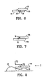
- the bed knife 18, illustrated in Fig. 5, is magnetically held against the magnets 20 in an operating position as illustrated in Fig. 6 such that the bed knife 18 is oriented in cutting relationship with the reel 2 in the same fashion as the bed knife 8 of the prior art illustrated in Fig. 2.
- Engagement means are operative to prevent sliding movement of the bed knife 18 with respect to the magnets 20.
- the engagement means comprises a plurality of protrusions, illustrated as pegs 26, extending from the bed bar 16 into a corresponding recess, illustrated as a hole 28, in the bed knife 18.
- the pegs 32 could extend up from the bed knife 18A into corresponding holes 34 in the bed knife 16A.
- Further engagement means are illustrated in Fig. 6 as a ridge 30 bearing against opposite end edges 18A and rear edge 18B of the bed knife 18.
- the engagement means While preventing sliding movement, the engagement means, illustrated as pegs 26 in holes 28, and as ridge 30, but also including other means, also allows the bed knife 18 to move away from the magnets 20 when a separating force is exerted on the bed knife 18 in a direction away from the magnets 20 that is greater than an attractive force exerted on the bed knife 18 by the magnets 20 when the bed knife 18 is in the operating position. While allowing the bed knife 18 to be easily removed by prying it away from the bed bar 16, this configuration also allows the bed knife to release from the bed bar 16 when an obstruction is encountered.
- Fig. 8 illustrates schematically contact of the bed knife 18 moving in direction T with a typical obstruction ill as a partially buried stone 40.
- the contact causes a force F to be exerted on the bed knife 18.
- the major component of this force F is exerted rearward, as illustrated by the arrow FR, however there is also a smaller component FD exerted downward such that the bed knife 18 is pushed away from the bed bar 16 and the magnets 20.
- this component of force FD exceeds the magnetic attractive force of the magnets 20 the bed knife 18 will release from the bed bar 16.
- more damage would occur, since the bed knife would have to ride over the obstruction.
- a stone or the like comes between the reel and the bed knife, a like force is exerted which can release the bed knife, reducing the possibility of severe damage to the reel which can be costly to repair.
- the ridge 30 alone could provide satisfactory operation with a new bed knife 18, as same essentially forms a low pocket that closely fits the edges 18A, 18B of the bed knife 18. Sideways and rearward sliding movement with respect to the magnets 20 is thus prevented. It is however possible to make the bed knife 18 double edged such that the front and rear edges 18C, 18B are both cutting edges.
- the holes 28 and pegs 26 are oriented such that the bed knife 18 can be rotated bringing the rear cutting edge 18B to the front, thereby doubling the life of the bed knife 18. With such a double edged bed knife 18, the front edge becomes worn and rounded duting use such that the ridge bears against a rounded edge that may slide over the ridge when rearward forces are applied.
- the pegs and holes are not affected by wear on the bed knife edges and will maintain the bed knife in position when it is rotated.
- the use of the ridge 30 in combination with the pegs 26 and holes 28 helps to align the bed knife with the pegs during installation.
- the present invention could be practiced in a number of fashions including by manufacturing new reel cutting assemblies in accordance with the present invention, or alternatively, by producing a retrofit bed bar or support frame kit which would allow the magnetic blade attachment of the present invention to be implemented on an existing mower.
Landscapes
- Life Sciences & Earth Sciences (AREA)
- Environmental Sciences (AREA)
- Harvester Elements (AREA)
- Constituent Portions Of Griding Lathes, Driving, Sensing And Control (AREA)
- Finish Polishing, Edge Sharpening, And Grinding By Specific Grinding Devices (AREA)
Claims (11)
- Baugruppe für einen Spindelmäher, welche folgendes aufweist:eine drehbar an einem Rahmen (4) angebrachte Mäherspindel (32) sowie einen Antrieb, der zum wirksamen Drehantrieb der Spindel um eine Spindelachse (RA) vorgesehen ist, gekennzeichnet durch:mindestens einen am Rahmen angebrachten Magneten (20);eine Einbauklinge bzw. ein Schnitzelmesser (18), die in einer Betriebsstellung magnetisch gegen den Magneten (20) so gehalten wird, dass die Einbauklinge in einer Schneidbeziehung zur Spindel (2) ausgerichtet ist, undeine Eingriffseinrichtung (26; 28; 30), welche in der Weise wirksam ist, dass sie eine Verschiebebewegung der Einbauklinge (18) bezüglich des Magneten (20) verhindert unddabei eine Bewegung der Einbauklinge vom Magneten weg zulässt, wenn auf die Einbauklinge eine Trennkraft in einer Richtung vom Magneten weg ausgeübt wird, die größer ist als eine vom Magneten auf die Einbauklinge ausgeübte Anziehungskraft, wenn sich die Einbauklinge in ihrer Betriebsstellung befindet.
- Baugruppe nach Anspruch 1, bei welcher die Eingriffseinrichtung (26; 28; 30) mindestens einen Vorsprung (26) aufweist, der sich von dem Rahmen oder von der Einbauklinge aus in eine entsprechende Vertiefung (28) in dem jeweils anderen Element, nämlich der Einbauklinge (18) oder dem Rahmen, hinein erstreckt
- Baugruppe nach einem der Ansprüche 1 und 2, wobei die Eingriffseinrichtung (26; 28; 30) mindestens eine Rippe (30) aufweist, die an dem Rahmen angebracht ist und gegen eine Kante (18B; 18C) der Einbauklinge (18) anliegt bzw. drückt
- Baugruppe nach einem der Ansprüche 1 bis 3, bei welcher der Rahmen (4) des Weiteren eine Einbauleiste (16) aufweist, die im Wesentlichen parallel zur Spindelachse (RA) verläuft, und bei welcher mindestens ein Magnet (20) an der Einbauleiste (16) angebracht ist
- Baugruppe nach Anspruch 4, bei welcher die Eingriffseinrichtung (26; 28; 30) aus der Einbauleiste (16) und der Einbauklinge (18) gebildet ist
- Vorrichtung zur Anbringung an einer Baugruppe für einen Spindelmäher, welche eine Mäherspindel (2) aufweist, die drehbar an einem Rahmen (4) angebracht ist, sowie einen Antrieb, der zum wirksamen Drehantrieb der Spindel um eine Spindelachse (RA) vorgesehen ist,
dadurch gekennzeichnet, dass die Vorrichtung folgendes ausweist:eine Einbauleiste (16), die zur Anbringung an dem Rahmen (4) im Wesentlichen parallel zur Spindelachse (RA) ausgelegt ist;eine Vielzahl von Magneten (20), die auf der Einbauleiste (16) angebracht ist;eine Einbauklinge bzw. ein Schnitzelmesset (18), die magnetisch gegen die Magneten (20) in einer Betriebsstellung in der Weise gehalten ist, dass die Einbauklinge in Schneidbeziehung zur Spindel (2) ausgerichtet ist, wenn die Einbauleiste (16) an dem Rahmen angebracht ist; undeine Eingriffseinrichtung (26; 28; 30), welche in der Weise wirksam ist, dass sie eine Verschiebebewegung der Einbauklinge (18) bezüglich der Magnete (20) verhindert und dabei eine Bewegung der Einbauklinge von den Magneten weg zulässt, wenn auf die Einbauklinge eine Trennkraft in einer Richtung von den Magneten weg ausgeübt wird, die größer ist als die von den Magneten auf die Einbauklinge ausgeübte Anziehungskraft, wenn sich die Einbauklinge in ihrer Betriebsstellung befindet - Vorrichtung nach Anspruch 6, bei welcher die Eingriffseinrichtung (26; 28; 30) mindestens einen Vorsprung (26) aufweist, der sich von der Einbauleiste (16) oder von der Einbauklinge (18) aus in eine entsprechende Vertiefung (28) in dem jeweils anderen Element, nämlich der Einbauklinge (18) oder der Einbauleiste, hinein erstreckt.
- Vorrichtung nach einem der Ansprüche 6 und 7, bei welcher die Eingriffseinrichtung (26; 28; 30) mindestens eine Rippe (30) aufweist, die an der Einbauleiste (16) angebracht ist und gegen eine Kante der Einbauklinge (18) anliegt bzw. drückt.
- Verfahren zum Halten einer Einbauklinge bzw. eines Schnitzelmessers (18) einer Baugruppe für einen Spindelmäher in einer Betriebsstellung, wobei die Baugruppe für den Spindelmäher eine drehbar an einem Rahmen (4) angebrachte Mäherspindel (2) sowie einen Antrieb, der zum wirksamen Drehantrieb der Spindel um eine Spindelachse (RA) vorgesehen ist, aufweist, wobei die Betriebsstellung so gestaltet ist, dass die Einbauklinge (18) in einer Schneidbeziehung zur Spindel (2) ausgerichtet ist,
dadurch gekennzeichnet, dass das Verfahren die folgenden Schritte umfasst:Anbringen von mindestens einem Magneten (20) an dem Rahmen (4);magnetisches Halten der Einbauklinge (18) gegen den Magneten (20) in der Betriebsstellung; undVerhindern einer Verschiebebewegung der Einbauklinge (18) bezüglich des Magneten (20) und dabei Zulassen einer Bewegung der Einbauklinge von dem Magneten weg, wenn auf die Einbauklinge eine Trennkraft in einer Richtung vom Magneten weg ausgeübt wird, die größer ist als die vom Magneten auf die Einbauklinge ausgeübte Anziehungskraft, wenn sich die Einbauklinge ihrer Betriebsstellung befindet - Verfahren nach Anspruch 9, bei welchem eine Verschiebebewegung dadurch verhindert wird, dass mindestens ein Vorsprung (26) vorgesehen ist, der sich von dem Rahmen (4) oder der Einbauklinge (18) aus in eine entsprechende Vertiefung (28) in dem anderen Element, nämlich der Einbauklinge oder dem Rahmen, hinein erstreckt
- Verfahren nach einem der Ansprüche 9 und 10, bei welchem eine Verschiebebewegung dadurch verhindert wird, dass mindestens eine Rippe (30) vorgesehen ist, die an dem Rahmen angebracht ist und gegen eine Kante (18B; 18C) der Einbauklinge (18) anliegt bzw. drückt.
Priority Applications (1)
| Application Number | Priority Date | Filing Date | Title |
|---|---|---|---|
| EP05011206A EP1600048B1 (de) | 2002-06-07 | 2002-08-19 | Magnetische Befestigung des Gegenmessers für Spindelmäher |
Applications Claiming Priority (7)
| Application Number | Priority Date | Filing Date | Title |
|---|---|---|---|
| CA2389770 | 2002-06-07 | ||
| CA 2389770 CA2389770A1 (en) | 2002-06-07 | 2002-06-07 | Magnetic attachment of bedknife in a reel mower assembly |
| CA002394085A CA2394085C (en) | 2002-06-07 | 2002-07-18 | Magnetic attachment of a bedknife in a reel mower assembly |
| CA2394085 | 2002-07-18 | ||
| US201841 | 2002-07-24 | ||
| US10/201,841 US6889491B2 (en) | 2002-06-07 | 2002-07-24 | Magnetic attachment of a bed knife in a reel mower assembly |
| PCT/CA2002/001280 WO2003103374A1 (en) | 2002-06-07 | 2002-08-19 | Magnetic attachment of a bed knife in a reel mower assembly |
Related Child Applications (1)
| Application Number | Title | Priority Date | Filing Date |
|---|---|---|---|
| EP05011206A Division EP1600048B1 (de) | 2002-06-07 | 2002-08-19 | Magnetische Befestigung des Gegenmessers für Spindelmäher |
Publications (2)
| Publication Number | Publication Date |
|---|---|
| EP1467609A1 EP1467609A1 (de) | 2004-10-20 |
| EP1467609B1 true EP1467609B1 (de) | 2005-05-25 |
Family
ID=29740337
Family Applications (1)
| Application Number | Title | Priority Date | Filing Date |
|---|---|---|---|
| EP02752923A Expired - Lifetime EP1467609B1 (de) | 2002-06-07 | 2002-08-19 | Magnetische befestigung des gegenmessers für spindelmäher |
Country Status (9)
| Country | Link |
|---|---|
| EP (1) | EP1467609B1 (de) |
| JP (1) | JP3944527B2 (de) |
| CN (1) | CN1309293C (de) |
| AT (1) | ATE296024T1 (de) |
| AU (1) | AU2002313429A1 (de) |
| DE (1) | DE60204364T2 (de) |
| ES (1) | ES2240777T3 (de) |
| NZ (1) | NZ527100A (de) |
| WO (1) | WO2003103374A1 (de) |
Families Citing this family (5)
| Publication number | Priority date | Publication date | Assignee | Title |
|---|---|---|---|---|
| EP1593297A1 (de) * | 2004-05-04 | 2005-11-09 | Textron Inc. | Gegenmesseranordnung für Spindelmäher |
| US20050246885A1 (en) * | 2004-05-04 | 2005-11-10 | Mahan Jonathan D F | Bed knife and method of forming |
| US20050247039A1 (en) * | 2004-05-04 | 2005-11-10 | Textron Inc. | Disposable magnetic bedknife |
| US20050247040A1 (en) * | 2004-05-04 | 2005-11-10 | Textron Inc. | Disposable bedknife for a mower |
| EP1609347A1 (de) * | 2004-05-04 | 2005-12-28 | Textron Inc. | Gegenmesseranordnung für Spindelmäher |
Family Cites Families (8)
| Publication number | Priority date | Publication date | Assignee | Title |
|---|---|---|---|---|
| DE3803711A1 (de) * | 1988-02-04 | 1989-08-17 | Thrige Agro As | Steckbolzen mit einem axialen sicherungselement fuer landwirtschaftliche vorrichtungen oder maschinen |
| US5291724A (en) * | 1992-02-14 | 1994-03-08 | T.I. International, Inc. | Reel assembly for mower |
| US5279100A (en) * | 1992-09-22 | 1994-01-18 | Hay & Forage Industries | Self-latching shield curtain for crop harvesters |
| US5477666A (en) * | 1993-08-20 | 1995-12-26 | T.I. International, Inc. | Reel assembly for mower |
| DE19735698A1 (de) * | 1997-08-16 | 1999-02-18 | Deere & Co | Verbindung einer Gegenschneide und eines Gegenschneidehalters, Gegenschneide oder Gegenschneidehalter und Maschine |
| US6044637A (en) * | 1998-01-30 | 2000-04-04 | Deere & Company | Bedknife adjustment linkage |
| US6318059B1 (en) * | 2000-01-28 | 2001-11-20 | Bush Hog, L.L.C. | Mower and reel with axially offset chevron blade apexes |
| CN201811712U (zh) * | 2010-08-31 | 2011-04-27 | 东莞市迈恩传感科技有限公司 | 线轮补偿式高精度拉绳位移传感器 |
-
2002
- 2002-08-19 AT AT02752923T patent/ATE296024T1/de not_active IP Right Cessation
- 2002-08-19 CN CNB028290739A patent/CN1309293C/zh not_active Expired - Fee Related
- 2002-08-19 WO PCT/CA2002/001280 patent/WO2003103374A1/en not_active Ceased
- 2002-08-19 NZ NZ527100A patent/NZ527100A/en unknown
- 2002-08-19 AU AU2002313429A patent/AU2002313429A1/en not_active Abandoned
- 2002-08-19 EP EP02752923A patent/EP1467609B1/de not_active Expired - Lifetime
- 2002-08-19 JP JP2004510515A patent/JP3944527B2/ja not_active Expired - Fee Related
- 2002-08-19 DE DE60204364T patent/DE60204364T2/de not_active Expired - Lifetime
- 2002-08-19 ES ES02752923T patent/ES2240777T3/es not_active Expired - Lifetime
Also Published As
| Publication number | Publication date |
|---|---|
| WO2003103374A1 (en) | 2003-12-18 |
| JP3944527B2 (ja) | 2007-07-11 |
| EP1467609A1 (de) | 2004-10-20 |
| JP2005519638A (ja) | 2005-07-07 |
| CN1309293C (zh) | 2007-04-11 |
| ATE296024T1 (de) | 2005-06-15 |
| DE60204364D1 (de) | 2005-06-30 |
| AU2002313429A1 (en) | 2003-12-22 |
| NZ527100A (en) | 2006-11-30 |
| CN1627897A (zh) | 2005-06-15 |
| ES2240777T3 (es) | 2005-10-16 |
| DE60204364T2 (de) | 2006-02-02 |
Similar Documents
| Publication | Publication Date | Title |
|---|---|---|
| EP1600048B1 (de) | Magnetische Befestigung des Gegenmessers für Spindelmäher | |
| US7434380B2 (en) | Magnetic attachment of a bed knife in a reel mower assembly | |
| AU2002313429A1 (en) | Magnetic attachment of a bed knife in a reel mower assembly | |
| US5163276A (en) | Multi-purpose attachments for power lawn mower blades | |
| US7644568B2 (en) | Serrated edge bed knife | |
| US3455093A (en) | Adjusting holddown clip | |
| US20050246885A1 (en) | Bed knife and method of forming | |
| US20120017559A1 (en) | Magnetic drive connection for a reel mower | |
| US20060123760A1 (en) | Lawnmower with projections for lifting grass and method of cutting grass | |
| US6301867B1 (en) | Bed knife blade construction for reel mowers | |
| US20070137161A1 (en) | Disposable magnetic bedknife | |
| US20050066553A1 (en) | Snow blower with glide wheels | |
| CA2389770A1 (en) | Magnetic attachment of bedknife in a reel mower assembly | |
| US8042321B2 (en) | Magnetic connection of driving and driven connection for a reel mower | |
| CA2490960A1 (en) | Bed knife and method of forming | |
| EP1609347A1 (de) | Gegenmesseranordnung für Spindelmäher | |
| US20050247040A1 (en) | Disposable bedknife for a mower | |
| EP1593297A1 (de) | Gegenmesseranordnung für Spindelmäher |
Legal Events
| Date | Code | Title | Description |
|---|---|---|---|
| PUAI | Public reference made under article 153(3) epc to a published international application that has entered the european phase |
Free format text: ORIGINAL CODE: 0009012 |
|
| GRAP | Despatch of communication of intention to grant a patent |
Free format text: ORIGINAL CODE: EPIDOSNIGR1 |
|
| 17P | Request for examination filed |
Effective date: 20030728 |
|
| AK | Designated contracting states |
Kind code of ref document: A1 Designated state(s): AT BE BG CH CY CZ DE DK EE ES FI FR GB GR IE IT LI LU MC NL PT SE SK TR |
|
| AX | Request for extension of the european patent |
Extension state: AL LT LV MK RO SI |
|
| GRAS | Grant fee paid |
Free format text: ORIGINAL CODE: EPIDOSNIGR3 |
|
| GRAA | (expected) grant |
Free format text: ORIGINAL CODE: 0009210 |
|
| AK | Designated contracting states |
Kind code of ref document: B1 Designated state(s): AT BE BG CH CY CZ DE DK EE ES FI FR GB GR IE IT LI LU MC NL PT SE SK TR |
|
| PG25 | Lapsed in a contracting state [announced via postgrant information from national office to epo] |
Ref country code: CH Free format text: LAPSE BECAUSE OF FAILURE TO SUBMIT A TRANSLATION OF THE DESCRIPTION OR TO PAY THE FEE WITHIN THE PRESCRIBED TIME-LIMIT Effective date: 20050525 Ref country code: BE Free format text: LAPSE BECAUSE OF FAILURE TO SUBMIT A TRANSLATION OF THE DESCRIPTION OR TO PAY THE FEE WITHIN THE PRESCRIBED TIME-LIMIT Effective date: 20050525 Ref country code: EE Free format text: LAPSE BECAUSE OF FAILURE TO SUBMIT A TRANSLATION OF THE DESCRIPTION OR TO PAY THE FEE WITHIN THE PRESCRIBED TIME-LIMIT Effective date: 20050525 Ref country code: TR Free format text: LAPSE BECAUSE OF FAILURE TO SUBMIT A TRANSLATION OF THE DESCRIPTION OR TO PAY THE FEE WITHIN THE PRESCRIBED TIME-LIMIT Effective date: 20050525 Ref country code: CZ Free format text: LAPSE BECAUSE OF FAILURE TO SUBMIT A TRANSLATION OF THE DESCRIPTION OR TO PAY THE FEE WITHIN THE PRESCRIBED TIME-LIMIT Effective date: 20050525 Ref country code: SK Free format text: LAPSE BECAUSE OF FAILURE TO SUBMIT A TRANSLATION OF THE DESCRIPTION OR TO PAY THE FEE WITHIN THE PRESCRIBED TIME-LIMIT Effective date: 20050525 Ref country code: LI Free format text: LAPSE BECAUSE OF FAILURE TO SUBMIT A TRANSLATION OF THE DESCRIPTION OR TO PAY THE FEE WITHIN THE PRESCRIBED TIME-LIMIT Effective date: 20050525 Ref country code: FI Free format text: LAPSE BECAUSE OF FAILURE TO SUBMIT A TRANSLATION OF THE DESCRIPTION OR TO PAY THE FEE WITHIN THE PRESCRIBED TIME-LIMIT Effective date: 20050525 Ref country code: AT Free format text: LAPSE BECAUSE OF FAILURE TO SUBMIT A TRANSLATION OF THE DESCRIPTION OR TO PAY THE FEE WITHIN THE PRESCRIBED TIME-LIMIT Effective date: 20050525 Ref country code: NL Free format text: LAPSE BECAUSE OF FAILURE TO SUBMIT A TRANSLATION OF THE DESCRIPTION OR TO PAY THE FEE WITHIN THE PRESCRIBED TIME-LIMIT Effective date: 20050525 |
|
| REG | Reference to a national code |
Ref country code: GB Ref legal event code: FG4D |
|
| REG | Reference to a national code |
Ref country code: CH Ref legal event code: EP |
|
| REG | Reference to a national code |
Ref country code: IE Ref legal event code: FG4D |
|
| REF | Corresponds to: |
Ref document number: 60204364 Country of ref document: DE Date of ref document: 20050630 Kind code of ref document: P |
|
| PG25 | Lapsed in a contracting state [announced via postgrant information from national office to epo] |
Ref country code: IT Free format text: LAPSE BECAUSE OF NON-PAYMENT OF DUE FEES Effective date: 20050819 Ref country code: IE Free format text: LAPSE BECAUSE OF NON-PAYMENT OF DUE FEES Effective date: 20050819 Ref country code: CY Free format text: LAPSE BECAUSE OF FAILURE TO SUBMIT A TRANSLATION OF THE DESCRIPTION OR TO PAY THE FEE WITHIN THE PRESCRIBED TIME-LIMIT Effective date: 20050819 |
|
| PG25 | Lapsed in a contracting state [announced via postgrant information from national office to epo] |
Ref country code: ES Free format text: LAPSE BECAUSE OF NON-PAYMENT OF DUE FEES Effective date: 20050820 Ref country code: SE Free format text: LAPSE BECAUSE OF NON-PAYMENT OF DUE FEES Effective date: 20050820 |
|
| PG25 | Lapsed in a contracting state [announced via postgrant information from national office to epo] |
Ref country code: GR Free format text: LAPSE BECAUSE OF FAILURE TO SUBMIT A TRANSLATION OF THE DESCRIPTION OR TO PAY THE FEE WITHIN THE PRESCRIBED TIME-LIMIT Effective date: 20050825 Ref country code: DK Free format text: LAPSE BECAUSE OF FAILURE TO SUBMIT A TRANSLATION OF THE DESCRIPTION OR TO PAY THE FEE WITHIN THE PRESCRIBED TIME-LIMIT Effective date: 20050825 Ref country code: BG Free format text: LAPSE BECAUSE OF FAILURE TO SUBMIT A TRANSLATION OF THE DESCRIPTION OR TO PAY THE FEE WITHIN THE PRESCRIBED TIME-LIMIT Effective date: 20050825 |
|
| REG | Reference to a national code |
Ref country code: SE Ref legal event code: TRGR |
|
| PG25 | Lapsed in a contracting state [announced via postgrant information from national office to epo] |
Ref country code: MC Free format text: LAPSE BECAUSE OF NON-PAYMENT OF DUE FEES Effective date: 20050831 |
|
| REG | Reference to a national code |
Ref country code: ES Ref legal event code: FG2A Ref document number: 2240777 Country of ref document: ES Kind code of ref document: T3 |
|
| PG25 | Lapsed in a contracting state [announced via postgrant information from national office to epo] |
Ref country code: PT Free format text: LAPSE BECAUSE OF FAILURE TO SUBMIT A TRANSLATION OF THE DESCRIPTION OR TO PAY THE FEE WITHIN THE PRESCRIBED TIME-LIMIT Effective date: 20051027 |
|
| REG | Reference to a national code |
Ref country code: CH Ref legal event code: PL |
|
| NLV1 | Nl: lapsed or annulled due to failure to fulfill the requirements of art. 29p and 29m of the patents act | ||
| ET | Fr: translation filed | ||
| PLBE | No opposition filed within time limit |
Free format text: ORIGINAL CODE: 0009261 |
|
| STAA | Information on the status of an ep patent application or granted ep patent |
Free format text: STATUS: NO OPPOSITION FILED WITHIN TIME LIMIT |
|
| EUG | Se: european patent has lapsed | ||
| 26N | No opposition filed |
Effective date: 20060228 |
|
| REG | Reference to a national code |
Ref country code: IE Ref legal event code: MM4A |
|
| REG | Reference to a national code |
Ref country code: ES Ref legal event code: FD2A Effective date: 20050820 |
|
| REG | Reference to a national code |
Ref country code: GB Ref legal event code: 732E |
|
| REG | Reference to a national code |
Ref country code: FR Ref legal event code: RM Ref country code: FR Ref legal event code: TP |
|
| REG | Reference to a national code |
Ref country code: FR Ref legal event code: PLFP Year of fee payment: 14 |
|
| PGFP | Annual fee paid to national office [announced via postgrant information from national office to epo] |
Ref country code: DE Payment date: 20150827 Year of fee payment: 14 Ref country code: GB Payment date: 20150827 Year of fee payment: 14 |
|
| PGFP | Annual fee paid to national office [announced via postgrant information from national office to epo] |
Ref country code: FR Payment date: 20150817 Year of fee payment: 14 |
|
| REG | Reference to a national code |
Ref country code: DE Ref legal event code: R119 Ref document number: 60204364 Country of ref document: DE |
|
| GBPC | Gb: european patent ceased through non-payment of renewal fee |
Effective date: 20160819 |
|
| REG | Reference to a national code |
Ref country code: FR Ref legal event code: ST Effective date: 20170428 |
|
| PG25 | Lapsed in a contracting state [announced via postgrant information from national office to epo] |
Ref country code: FR Free format text: LAPSE BECAUSE OF NON-PAYMENT OF DUE FEES Effective date: 20160831 Ref country code: DE Free format text: LAPSE BECAUSE OF NON-PAYMENT OF DUE FEES Effective date: 20170301 Ref country code: GB Free format text: LAPSE BECAUSE OF NON-PAYMENT OF DUE FEES Effective date: 20160819 |