EP1467896B1 - Procede, dispositif et systeme pouvant empecher un deploiement accidentel d'un dispositif de securite arme d'un vehicule ou d'une embarcation - Google Patents
Procede, dispositif et systeme pouvant empecher un deploiement accidentel d'un dispositif de securite arme d'un vehicule ou d'une embarcation Download PDFInfo
- Publication number
- EP1467896B1 EP1467896B1 EP03701931A EP03701931A EP1467896B1 EP 1467896 B1 EP1467896 B1 EP 1467896B1 EP 03701931 A EP03701931 A EP 03701931A EP 03701931 A EP03701931 A EP 03701931A EP 1467896 B1 EP1467896 B1 EP 1467896B1
- Authority
- EP
- European Patent Office
- Prior art keywords
- craft
- vehicle
- ignition
- motor
- safety
- Prior art date
- Legal status (The legal status is an assumption and is not a legal conclusion. Google has not performed a legal analysis and makes no representation as to the accuracy of the status listed.)
- Expired - Lifetime
Links
- 238000000034 method Methods 0.000 title claims abstract description 10
- 239000002360 explosive Substances 0.000 claims abstract description 17
- 238000001514 detection method Methods 0.000 claims abstract description 10
- 230000004044 response Effects 0.000 claims abstract description 8
- 230000003111 delayed effect Effects 0.000 claims abstract description 5
- 230000001419 dependent effect Effects 0.000 claims description 6
- 230000003213 activating effect Effects 0.000 claims description 5
- 230000004913 activation Effects 0.000 claims description 3
- 230000000903 blocking effect Effects 0.000 claims 4
- 238000012544 monitoring process Methods 0.000 claims 1
- 230000011664 signaling Effects 0.000 claims 1
- 239000003990 capacitor Substances 0.000 description 11
- 238000012423 maintenance Methods 0.000 description 7
- 230000006378 damage Effects 0.000 description 2
- 238000005474 detonation Methods 0.000 description 2
- 208000027418 Wounds and injury Diseases 0.000 description 1
- 230000002159 abnormal effect Effects 0.000 description 1
- 238000013475 authorization Methods 0.000 description 1
- 230000009849 deactivation Effects 0.000 description 1
- 230000001066 destructive effect Effects 0.000 description 1
- 238000007599 discharging Methods 0.000 description 1
- 239000000446 fuel Substances 0.000 description 1
- 230000006870 function Effects 0.000 description 1
- 231100001261 hazardous Toxicity 0.000 description 1
- 208000014674 injury Diseases 0.000 description 1
- 230000002045 lasting effect Effects 0.000 description 1
- 230000007659 motor function Effects 0.000 description 1
- 230000001012 protector Effects 0.000 description 1
- 230000008439 repair process Effects 0.000 description 1
- 230000000452 restraining effect Effects 0.000 description 1
- 230000005236 sound signal Effects 0.000 description 1
Images
Classifications
-
- B—PERFORMING OPERATIONS; TRANSPORTING
- B60—VEHICLES IN GENERAL
- B60R—VEHICLES, VEHICLE FITTINGS, OR VEHICLE PARTS, NOT OTHERWISE PROVIDED FOR
- B60R21/00—Arrangements or fittings on vehicles for protecting or preventing injuries to occupants or pedestrians in case of accidents or other traffic risks
- B60R21/01—Electrical circuits for triggering passive safety arrangements, e.g. airbags, safety belt tighteners, in case of vehicle accidents or impending vehicle accidents
- B60R21/017—Electrical circuits for triggering passive safety arrangements, e.g. airbags, safety belt tighteners, in case of vehicle accidents or impending vehicle accidents including arrangements for providing electric power to safety arrangements or their actuating means, e.g. to pyrotechnic fuses or electro-mechanic valves
Definitions
- safety devices including an explosive charge and passenger protection members such as airbags, belt tighteners, active head supports and roll bars, pedal protectors and other devices (hereinafter referred to as "safety devices") are used in motor vehides, aircraft and fast boats.
- the explosive charge is ignited and detonates in response to accident typical conditions sensed by sensors and are intended to protect the occupants of a vehicle against the impact of a crash or other serious accident, usually by restraining movement of the passenger relative to the vehicle or craft, but in some cases in other manners, such as by moving potentially hazardous obstacles such as pedals out of the way of the passengers.
- An example of such a system is disclosed in U.S. patent 6 052 634, which discloses the preamble of claim 7.
- German patent application 197 47 708 describes a system that allows disabling safety devices after an accident by operating destructive switches or by cutting power wires or signal wires visible in a special window. Deactivation by this system requires trained rescue personnel familiar with the system to enter the operating range of one or more of the safety devices.
- the safety devices will not always be secured by the system because many of the devices have an independent power source, which allow them to deploy even when disconnected from an external power source. In that case, cutting the power lines will not disarm the safety devices.
- the system can become unreliable when signal lines have been severed by an accident.
- this object is achieved by providing a safety device that operates in accordance with the method according to claim 1.
- the invention further provides a safety device according to claim 7, a passenger protection system according to claim 16 and a safety system according to claim 17 that are specifically adapted for use in the method according to claim 1.
- This invention is based on the insight that useful deployment of safety devices is only indicated when a craft or vehicle is in an operating condition in which there is a risk of an accident with passengers on board, such as, while moving and/or under motor power or at least until a short time after an accident condition has been sensed, and in a short period after that.
- activation of safety devices is dependent on a running motor: it arms safety devices automatically after starting the engine, and it disarms them a short time after stopping of or shutting down the engine. After a serious accident, the motor will stop by itself or by triggering of sensors, after which any remaining safety devices will be automatically disarmed and locked. An automatic fuel cut-off will also stop the motor. After a lesser impact and during maintenance, the motor will be switched off manually, after which the safety devices will also be disarmed. The delayed disarming of the safety devices may also be made dependent on the coming to a stop of the craft or vehicle or directly dependent on the detection of an accident condition.
- An abnormal condition of the safety devices can be indicated on the dashboard, for example by an indicator light.
- Many safety devices include a capacitor for the storage of energy, which enables deployment of the safety device, even when cut off from the main power supply of a vehicle or craft.
- sarming may for instance be achieved by allowing charging of the capacitor only after the starting of the engine of a vehicle or craft and while the motor is running. After the stopping of the engine, the charging of this capacitor is blocked. A predetermined time after the engine has stopped the disarming electronics completely discharges this capacitor. At about the same time switches are operated causing the igniters to be isolated from the ignition control circuits and the igniters to be short-circuited, effectively locking the ignition electrically.
- switches are preferably of the normally disconnecting type and a short-circuit is preferably situated directly at or integrated into the igniters.
- a short-circuit is preferably situated directly at or integrated into the igniters.
- an active modulated signal for instance an alternating current
- the switches can be of the smart type, including a timing function, throwing the switches shortly after being activated by the modulated signal, and resetting themselves automatically with some delay (for instance about two minutes) after the modulated signal stops.
- These switches of which operation requires a modulated signal, make igniters remote from the ignition control circuits a safe option. In locked position, the igniters cannot be activated unintended, not even by a short-circuit after an accident or by an erroneous signal from the ignition control circuit.
- a short-circuiting switch is provided for each igniter. Shortly after the engine stops running, the explosive charges of safety devices cannot be activated and these are automatically and securely locked until the motor starts running again.
- the power supply in the ignition capacitor can be used as power supply for the electronics of the disarming circuitry itself.
- a dedicated capacitor may be provided to supply the disarming circuitry and to keep its timers and control circuits independent of the main power supply for a short time but long enough to securely disarm and lock all safety devices when indicated.
- the disarming may be signalled by a short sound signal. Even safety devices removed from a vehicle or craft, which at times have been known to deploy unexpectedly, will be safer: because of the absence of the signal of a running motor, the switch will automatically disarm and lock the safety device.
- the delay time of the disarming system can be adjusted to a shorter time if desired, or to a longer time when at high speed. Experience or law may dictate other delay times, the essential being that the proposed way of disarming gives complete assurance that all explosive charged safety devices will be disarmed a predetermined time after the end of the operating condition in which their armed condition is desired has ended.
- the indication of for instance a running motor may be acquired in different ways.
- Input can be via a separate data-line from the motor management system.
- the ripple on the main power lines caused by the alternator or the ignition can be detected by a separate detector or by a detector included in the safety device or in a safety device control unit to detect a running motor.
- a simple receiver circuit e.g. a tuned circuit
- the essential is the detection of a running motor or other indication of the operating condition required to allow detonation of the safety devices.
- a dedicated switch can be fitted in the motor compartment to interrupt the signal of a running motor, in order to keep all safety devices disarmed and locked, even after starting the motor. Failure to reset this switch is preferably indicated by a prominent warning light on the dashboard.
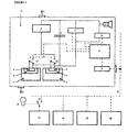
- Fig. 1 shows a schematic representation of a safety system including a safety device according to the invention.
- a safety device 17 has a power connection 1 to an external power supply and a returning power line 2 to the main vehicle battery.
- the system has an independent internal power supply 3, e.g. the ignition capacitor to safeguard an adequate time of proper functioning, even when disconnected from the main power supply.
- a charger 11 is incorporated in the device 17 for charging the capacitor 3.
- the ignition of the safety devices includes a control and ignition control circuit 4 and igniters 5 for igniting the explosives 6.
- the igniters are connected to and operated by the ignition control circuit 4 for controlling the igniters 5 of the explosive charges 6 to deploy the passenger protection members 7 when indicated. These may be the same as in commercially available safety devices.
- the disarming controller 8 is connected to obtain its input concerning speed and motor function via a data bus 10 and an input port 9 from a running motor detector 15 and a vehicle speed signal generator 16 to allow an optimal reaction to the environment.
- Other safety devices 19, 20 are connected to the same data bus 9.
- Smart switches 12 are connected to the controller 8 and connected for switching between a position connecting the ignition control circuit 4 and the igniters 5 and the shown position in which the contacts of each of the igniters 5 are short-circuited.
- the smart switches 12 are operated to disconnect the igniters 5 from the ignition control circuit 4 and to short-circuit their connections directly at the igniters 5, and a discharger 13 for discharging the capacitor 3 is activated.
- the locking of the safety device 17 can be indicated with a short warning signal 14.
- the switches 12 must preferably be electronic and of the normally open type, making an active modulated signal necessary to connect the ignition circuit 4 to the igniters 5.
- an active passenger restraint system may and will often include a plurality of safety devices and a detector for detecting the operating condition of the vehicle may be a central detector or each safety device or some of the safety devices may be provided with an associated detectors.
- a detector for detecting the operating condition of the vehicle may be a central detector or each safety device or some of the safety devices may be provided with an associated detectors.
- two or more of such items may be provided, which operate in co-operation, in parallel or in a back-up relationship.
Landscapes
- Engineering & Computer Science (AREA)
- Mechanical Engineering (AREA)
- Air Bags (AREA)
- Catching Or Destruction (AREA)
Claims (21)
- Procédé pour empêcher le déploiement accidentel ou retardé d'un élément de protection de passager (7) d'un dispositif de sécurité (17, 20, 21) dans un véhicule ou une embarcation, ledit dispositif de sécurité comprenant une charge explosive (6) et un dispositif d'amorçage (4, 5) pour amorcer la charge explosive (6), consistant à :- détecter la fin d'une condition de service du véhicule ou de l'embarcation, et- après un retard en réponse à la détection de la fin de la condition de service du véhicule ou de l'embarcation, actionner automatiquement le désarmement du dispositif d'amorçage (4, 5).
- Procédé selon la revendication 1, consistant à armer automatiquement le dispositif d'amorçage (4, 5) en réponse à la détection de ladite condition de service du véhicule ou de l'embarcation.
- Procédé selon la revendication 1 ou 2, dans lequel ledit véhicule ou ladite embarcation est motorisé et dans lequel au moins une caractéristique de ladite condition de service est que ledit moteur est en marche.
- Procédé selon la revendication 3, dans lequel le fonctionnement dudit moteur est détecté en détectant une ondulation d'alternateur dans l'alimentation électrique.
- Procédé selon la revendication 3 ou 4, dans lequel le fonctionnement dudit moteur est détecté par détection à distance d'un signal dédié généré quand le moteur est en marche.
- Procédé selon l'une quelconque des revendications précédentes, consistant en outre à détecter la vitesse du véhicule ou de l'embarcation et déterminer une durée dudit retard en fonction de la vitesse détectée.
- Dispositif de sécurité pour un véhicule ou une embarcation, comprenant :- un élément de protection de passager (7) pour protéger un passager en cas d'accident ;- une charge explosive (6) pour déployer l'élément de protection de passager (7) ;- un dispositif d'amorçage (4, 5) pour amorcer la charge explosive (6), et- des moyens de désarmement (8, 12, 9) caractérisé en ce que lesdits moyens de désarmement (8, 12, 9), après un retard en réponse à la détection à un signal indicatif de la fin de la condition de service du véhicule ou de l'embarcation, actionnent automatiquement le désarmement du dispositif d'amorçage (4, 5).
- Dispositif selon la revendication 7, dans lequel les moyens de désarmement (8, 12, 9) sont adaptés pour armer automatiquement le dispositif d'amorçage (4, 5) en réponse à la détection dudit signal indicatif de ladite condition de service dudit véhicule ou de ladite embarcation.
- Dispositif selon la revendication 7, comprenant en outre des moyens d'armement pour armer automatiquement le dispositif d'amorçage (4, 5) en réponse à la détection dudit signal indicatif de ladite condition de service dudit véhicule ou de ladite embarcation.
- Dispositif selon l'une quelconque des revendications 7 à 9, dans lequel lesdits moyens de désarmement comprennent un port d'entrée (9) pour recevoir le signal indicatif de la condition de service du véhicule ou de l'embarcation, un dispositif de contrôle (8) connecté au dit port d'entrée (9) et des éléments de désarmement (12), et dans lequel ledit port d'entrée (9), ledit dispositif de contrôle (8) et lesdits éléments de désarmement (12) sont intégrés dans ledit dispositif (17).
- Dispositif selon l'une quelconque des revendications 7 à 10, dans lequel le dispositif d'amorçage comprend un dispositif de contrôle d'amorçage (4) connecté à une amorce (5) pour commander l'amorce (5) et dans lequel lesdits moyens de désarmement comprennent un interrupteur (12) qui isole le dispositif de contrôle d'amorçage (4) de l'amorce (5).
- Dispositif selon la revendication 11, dans lequel ledit au moins un interrupteur (12) est du type normalement ouvert, qui est fermé seulement en présence d'un signal d'activation modulé indicatif de la condition de fonctionnement normal du véhicule ou de l'embarcation et adapté pour une réinitialisation automatique dans la condition ouverte avec un temps de retard après la cessation du signal modulé d'activation.
- Dispositif selon l'une quelconque des revendications précédentes 7 à 10, dans lequel le dispositif d'amorçage comprend une amorce (5) et dans lequel lesdits moyens de désarmement comprennent un interrupteur (12) pour court-circuiter l'amorce (5).
- Dispositif selon la revendication 13, dans lequel ledit au moins un interrupteur (12) pour court-circuiter l'amorce (5) est du type normalement fermé, qui est ouvert seulement en présence d'un signal d'activation modulé indicatif de la condition de fonctionnement normal du véhicule ou de l'embarcation et adapté pour une réinitialisation automatique dans la condition fermée avec un temps de retard après la cessation du signal modulé d'activation.
- Dispositif selon l'une quelconque des revendications 11 à 14, dans lequel ledit interrupteur est situé directement sur ou intégré dans l'amorce (5) des charges explosives (6).
- Système de protection de passager comprenant au moins un dispositif selon l'une quelconque des revendications 7 à 15.
- Système de sécurité pour empêcher le déploiement accidentel ou retardé à la suite d'un accident de coussins autogonflables de sécurité (7), tendeurs de ceinture, appuie-tête actifs, arceaux de sécurité actifs, protecteurs de pédale et autres dispositifs de sécurité dans un véhicule ou une embarcation utilisant des charges explosives ou pyrotechniques (6), dans lequel il désarme et verrouille tous les dispositifs de sécurité (17, 20, 21) dans un véhicule ou une embarcation un temps bref après l'arrêt ou l'extinction du moteur de ce véhicule ou cette embarcation, l'activation et l'armement de dispositifs de sécurité (17, 20, 21) étant effectués seulement après détection par le système de sécurité d'un moteur en marche, le système de sécurité étant intégré dans les circuits d'amorçage de tous les dispositifs de sécurité pour rendre ces systèmes indépendants d'un système de sécurité externe ou de connexions à un dispositif de sécurité externe.
- Système selon la revendication 16 ou 17, comprenant en outre un détecteur (15) pour détecter un moteur en marche du véhicule ou de l'embarcation en surveillant des fluctuations de tension induites par alternateur dans l'alimentation électrique.
- Système selon la revendication 18, dans lequel le détecteur (15) est adapté pour générer un signal en réponse à une détection du moteur en marche et dans lequel un port d'entrée (9) du système de sécurité est adapté pour recevoir ledit signal.
- Système selon l'une quelconque des revendications 16 à 19, comprenant en outre un interrupteur de blocage (18) pour bloquer la détection d'un moteur en marche.
- Système selon la revendication 20, comprenant en outre des moyens de signalisation (21) pour indiquer que ledit interrupteur de blocage (18) est dans ladite condition de blocage.
Applications Claiming Priority (3)
| Application Number | Priority Date | Filing Date | Title |
|---|---|---|---|
| NL1019796A NL1019796C2 (nl) | 2002-01-21 | 2002-01-21 | Een beveiligingssysteem voor het automatisch uitschakelen van airbags e.d. in een voertuig of vaartuig. |
| NL1019796 | 2002-01-21 | ||
| PCT/NL2003/000022 WO2003062021A1 (fr) | 2002-01-21 | 2003-01-15 | Procede, dispositif et systeme pouvant empecher un deploiement accidentel d'un dispositif de securite arme d'un vehicule ou d'une embarcation |
Publications (2)
| Publication Number | Publication Date |
|---|---|
| EP1467896A1 EP1467896A1 (fr) | 2004-10-20 |
| EP1467896B1 true EP1467896B1 (fr) | 2006-06-14 |
Family
ID=27607200
Family Applications (1)
| Application Number | Title | Priority Date | Filing Date |
|---|---|---|---|
| EP03701931A Expired - Lifetime EP1467896B1 (fr) | 2002-01-21 | 2003-01-15 | Procede, dispositif et systeme pouvant empecher un deploiement accidentel d'un dispositif de securite arme d'un vehicule ou d'une embarcation |
Country Status (5)
| Country | Link |
|---|---|
| EP (1) | EP1467896B1 (fr) |
| AT (1) | ATE329797T1 (fr) |
| DE (1) | DE60306111T2 (fr) |
| NL (1) | NL1019796C2 (fr) |
| WO (1) | WO2003062021A1 (fr) |
Cited By (1)
| Publication number | Priority date | Publication date | Assignee | Title |
|---|---|---|---|---|
| CN106170419A (zh) * | 2014-04-16 | 2016-11-30 | 罗伯特·博世有限公司 | 用于关断车辆的使用烟火技术的保护装置的点火器的至少一个点火输出级的方法及装置 |
Families Citing this family (4)
| Publication number | Priority date | Publication date | Assignee | Title |
|---|---|---|---|---|
| DE102004002881B4 (de) * | 2004-01-20 | 2009-05-07 | Trw Airbag Systems Gmbh | Gasgenerator, Gassackmodul und Verfahren zu ihrer Detektion |
| US20130043092A1 (en) * | 2011-08-17 | 2013-02-21 | Thomas W. Clardy | Integrated highly reliable person overboard self-rescue system |
| CN103085743B (zh) * | 2011-10-31 | 2015-10-07 | 上海博泰悦臻网络技术服务有限公司 | 车辆遇险的处理方法及装置、车载系统 |
| CN106379264A (zh) * | 2016-11-17 | 2017-02-08 | 卜凡春 | 汽车紧急逃生装置 |
Family Cites Families (5)
| Publication number | Priority date | Publication date | Assignee | Title |
|---|---|---|---|---|
| DE4137146A1 (de) * | 1991-11-12 | 1993-05-13 | Kern Johann Dipl Ing | Verfahren zur verhinderung der unabsichtlichen entladung des akkumulators einer transportvorrichtung, z.b. eines kfz und vorrichtung nach diesem verfahren |
| JPH0777141A (ja) * | 1993-08-31 | 1995-03-20 | Hitachi Automot Eng Co Ltd | 自動変速機付車両の遠隔始動装置 |
| FR2732286B1 (fr) * | 1995-03-31 | 1997-06-13 | Davey Bickford | Dispositif de securite d'un vehicule |
| DE19960179B4 (de) * | 1999-12-14 | 2009-08-20 | Volkswagen Ag | Sicherheitseinrichtung für Kraftfahrzeuge |
| US6296273B1 (en) * | 2000-02-22 | 2001-10-02 | David G. Lewallen | Automobile airbag deactivation system |
-
2002
- 2002-01-21 NL NL1019796A patent/NL1019796C2/nl not_active IP Right Cessation
-
2003
- 2003-01-15 EP EP03701931A patent/EP1467896B1/fr not_active Expired - Lifetime
- 2003-01-15 AT AT03701931T patent/ATE329797T1/de not_active IP Right Cessation
- 2003-01-15 DE DE60306111T patent/DE60306111T2/de not_active Expired - Fee Related
- 2003-01-15 WO PCT/NL2003/000022 patent/WO2003062021A1/fr not_active Ceased
Cited By (2)
| Publication number | Priority date | Publication date | Assignee | Title |
|---|---|---|---|---|
| CN106170419A (zh) * | 2014-04-16 | 2016-11-30 | 罗伯特·博世有限公司 | 用于关断车辆的使用烟火技术的保护装置的点火器的至少一个点火输出级的方法及装置 |
| CN106170419B (zh) * | 2014-04-16 | 2019-04-12 | 罗伯特·博世有限公司 | 用于关断车辆的使用烟火技术的保护装置的点火器的至少一个点火输出级的方法及装置 |
Also Published As
| Publication number | Publication date |
|---|---|
| DE60306111D1 (de) | 2006-07-27 |
| DE60306111T2 (de) | 2007-01-04 |
| EP1467896A1 (fr) | 2004-10-20 |
| WO2003062021A1 (fr) | 2003-07-31 |
| NL1019796C2 (nl) | 2003-07-23 |
| ATE329797T1 (de) | 2006-07-15 |
Similar Documents
| Publication | Publication Date | Title |
|---|---|---|
| EP2279092B1 (fr) | Procédé et appareil de mise au rebut de dispositifs de sécurité pyrotechniques | |
| US5749059A (en) | Apparatus and method for controlling an actuatable restraint device | |
| US5365114A (en) | Vehicle passenger restraint device for use in automotive vehicle or the like | |
| US5204547A (en) | Air bag system for protection of the occupants of motor vehicles | |
| EP0548849B1 (fr) | Dispositif de détection de collision pour sac gonflable latéral | |
| JP2559830B2 (ja) | 乗員抑止保護装置の作動方法および作動装置 | |
| EP0518501B1 (fr) | Circuit réconfigurable de mise à feu pour sac d'air | |
| US4366465A (en) | False failure detection prevention in an air bag diagnostic system | |
| US6615122B1 (en) | Impact judgement method and passenger protection device | |
| US20010052730A1 (en) | Process for triggering passenger protection systems | |
| US4673912A (en) | Vehicle-mounted triggering device and method of preventing false malfunction alarms in such a triggering device | |
| US3980318A (en) | Fused multiple stage inflation system | |
| EP0764095B1 (fr) | Procede de desactivation d'un sac gonflable de securite | |
| US5176214A (en) | Safety system for motor-vehicle occupants | |
| CN103832381A (zh) | 一种车窗玻璃边缘起爆逃生系统 | |
| WO2003062021A1 (fr) | Procede, dispositif et systeme pouvant empecher un deploiement accidentel d'un dispositif de securite arme d'un vehicule ou d'une embarcation | |
| EP1104725B1 (fr) | Système de retenue avec un générateur de gaz à niveaux multiples | |
| WO1998023470A1 (fr) | Ameliorations relatives a un circuit electronique de commande pour dispositif de securite de vehicule | |
| CN218228917U (zh) | 安全气囊控制系统和车辆 | |
| JP2004284382A (ja) | 乗員保護装置 | |
| JP2014141158A (ja) | 乗員保護制御装置 | |
| JP2694651B2 (ja) | 車両用乗員保護装置 | |
| US7048302B2 (en) | Electrical release circuit for a passenger protection system | |
| CN120168901A (zh) | 一种带有火灾预防系统的车辆、方法、电子设备以及介质 | |
| JP2005239059A (ja) | 車両用乗員保護装置 |
Legal Events
| Date | Code | Title | Description |
|---|---|---|---|
| PUAI | Public reference made under article 153(3) epc to a published international application that has entered the european phase |
Free format text: ORIGINAL CODE: 0009012 |
|
| 17P | Request for examination filed |
Effective date: 20040705 |
|
| AK | Designated contracting states |
Kind code of ref document: A1 Designated state(s): AT BE BG CH CY CZ DE DK EE ES FI FR GB GR HU IE IT LI LU MC NL PT SE SI SK TR |
|
| AX | Request for extension of the european patent |
Extension state: AL LT LV MK RO |
|
| 17Q | First examination report despatched |
Effective date: 20050706 |
|
| GRAP | Despatch of communication of intention to grant a patent |
Free format text: ORIGINAL CODE: EPIDOSNIGR1 |
|
| GRAS | Grant fee paid |
Free format text: ORIGINAL CODE: EPIDOSNIGR3 |
|
| GRAA | (expected) grant |
Free format text: ORIGINAL CODE: 0009210 |
|
| AK | Designated contracting states |
Kind code of ref document: B1 Designated state(s): AT BE BG CH CY CZ DE DK EE ES FI FR GB GR HU IE IT LI LU MC NL PT SE SI SK TR |
|
| PG25 | Lapsed in a contracting state [announced via postgrant information from national office to epo] |
Ref country code: IT Free format text: LAPSE BECAUSE OF FAILURE TO SUBMIT A TRANSLATION OF THE DESCRIPTION OR TO PAY THE FEE WITHIN THE PRESCRIBED TIME-LIMIT;WARNING: LAPSES OF ITALIAN PATENTS WITH EFFECTIVE DATE BEFORE 2007 MAY HAVE OCCURRED AT ANY TIME BEFORE 2007. THE CORRECT EFFECTIVE DATE MAY BE DIFFERENT FROM THE ONE RECORDED. Effective date: 20060614 Ref country code: LI Free format text: LAPSE BECAUSE OF FAILURE TO SUBMIT A TRANSLATION OF THE DESCRIPTION OR TO PAY THE FEE WITHIN THE PRESCRIBED TIME-LIMIT Effective date: 20060614 Ref country code: CZ Free format text: LAPSE BECAUSE OF FAILURE TO SUBMIT A TRANSLATION OF THE DESCRIPTION OR TO PAY THE FEE WITHIN THE PRESCRIBED TIME-LIMIT Effective date: 20060614 Ref country code: AT Free format text: LAPSE BECAUSE OF FAILURE TO SUBMIT A TRANSLATION OF THE DESCRIPTION OR TO PAY THE FEE WITHIN THE PRESCRIBED TIME-LIMIT Effective date: 20060614 Ref country code: FI Free format text: LAPSE BECAUSE OF FAILURE TO SUBMIT A TRANSLATION OF THE DESCRIPTION OR TO PAY THE FEE WITHIN THE PRESCRIBED TIME-LIMIT Effective date: 20060614 Ref country code: CH Free format text: LAPSE BECAUSE OF FAILURE TO SUBMIT A TRANSLATION OF THE DESCRIPTION OR TO PAY THE FEE WITHIN THE PRESCRIBED TIME-LIMIT Effective date: 20060614 Ref country code: SK Free format text: LAPSE BECAUSE OF FAILURE TO SUBMIT A TRANSLATION OF THE DESCRIPTION OR TO PAY THE FEE WITHIN THE PRESCRIBED TIME-LIMIT Effective date: 20060614 Ref country code: SI Free format text: LAPSE BECAUSE OF FAILURE TO SUBMIT A TRANSLATION OF THE DESCRIPTION OR TO PAY THE FEE WITHIN THE PRESCRIBED TIME-LIMIT Effective date: 20060614 |
|
| REG | Reference to a national code |
Ref country code: GB Ref legal event code: FG4D |
|
| REG | Reference to a national code |
Ref country code: CH Ref legal event code: EP |
|
| REG | Reference to a national code |
Ref country code: IE Ref legal event code: FG4D |
|
| REF | Corresponds to: |
Ref document number: 60306111 Country of ref document: DE Date of ref document: 20060727 Kind code of ref document: P |
|
| PG25 | Lapsed in a contracting state [announced via postgrant information from national office to epo] |
Ref country code: DK Free format text: LAPSE BECAUSE OF FAILURE TO SUBMIT A TRANSLATION OF THE DESCRIPTION OR TO PAY THE FEE WITHIN THE PRESCRIBED TIME-LIMIT Effective date: 20060914 |
|
| PG25 | Lapsed in a contracting state [announced via postgrant information from national office to epo] |
Ref country code: ES Free format text: LAPSE BECAUSE OF FAILURE TO SUBMIT A TRANSLATION OF THE DESCRIPTION OR TO PAY THE FEE WITHIN THE PRESCRIBED TIME-LIMIT Effective date: 20060925 |
|
| REG | Reference to a national code |
Ref country code: SE Ref legal event code: TRGR |
|
| PG25 | Lapsed in a contracting state [announced via postgrant information from national office to epo] |
Ref country code: PT Free format text: LAPSE BECAUSE OF FAILURE TO SUBMIT A TRANSLATION OF THE DESCRIPTION OR TO PAY THE FEE WITHIN THE PRESCRIBED TIME-LIMIT Effective date: 20061114 |
|
| REG | Reference to a national code |
Ref country code: CH Ref legal event code: PL |
|
| PG25 | Lapsed in a contracting state [announced via postgrant information from national office to epo] |
Ref country code: MC Free format text: LAPSE BECAUSE OF NON-PAYMENT OF DUE FEES Effective date: 20070131 |
|
| ET | Fr: translation filed | ||
| PLBE | No opposition filed within time limit |
Free format text: ORIGINAL CODE: 0009261 |
|
| STAA | Information on the status of an ep patent application or granted ep patent |
Free format text: STATUS: NO OPPOSITION FILED WITHIN TIME LIMIT |
|
| 26N | No opposition filed |
Effective date: 20070315 |
|
| PG25 | Lapsed in a contracting state [announced via postgrant information from national office to epo] |
Ref country code: GR Free format text: LAPSE BECAUSE OF FAILURE TO SUBMIT A TRANSLATION OF THE DESCRIPTION OR TO PAY THE FEE WITHIN THE PRESCRIBED TIME-LIMIT Effective date: 20060915 |
|
| PGFP | Annual fee paid to national office [announced via postgrant information from national office to epo] |
Ref country code: GB Payment date: 20080109 Year of fee payment: 6 Ref country code: IE Payment date: 20080107 Year of fee payment: 6 Ref country code: NL Payment date: 20080104 Year of fee payment: 6 Ref country code: SE Payment date: 20080124 Year of fee payment: 6 |
|
| PG25 | Lapsed in a contracting state [announced via postgrant information from national office to epo] |
Ref country code: BG Free format text: LAPSE BECAUSE OF FAILURE TO SUBMIT A TRANSLATION OF THE DESCRIPTION OR TO PAY THE FEE WITHIN THE PRESCRIBED TIME-LIMIT Effective date: 20060914 |
|
| PG25 | Lapsed in a contracting state [announced via postgrant information from national office to epo] |
Ref country code: EE Free format text: LAPSE BECAUSE OF FAILURE TO SUBMIT A TRANSLATION OF THE DESCRIPTION OR TO PAY THE FEE WITHIN THE PRESCRIBED TIME-LIMIT Effective date: 20060614 |
|
| PGFP | Annual fee paid to national office [announced via postgrant information from national office to epo] |
Ref country code: DE Payment date: 20080229 Year of fee payment: 6 Ref country code: FR Payment date: 20071228 Year of fee payment: 6 |
|
| PGFP | Annual fee paid to national office [announced via postgrant information from national office to epo] |
Ref country code: BE Payment date: 20080118 Year of fee payment: 6 |
|
| PG25 | Lapsed in a contracting state [announced via postgrant information from national office to epo] |
Ref country code: CY Free format text: LAPSE BECAUSE OF FAILURE TO SUBMIT A TRANSLATION OF THE DESCRIPTION OR TO PAY THE FEE WITHIN THE PRESCRIBED TIME-LIMIT Effective date: 20060614 Ref country code: LU Free format text: LAPSE BECAUSE OF NON-PAYMENT OF DUE FEES Effective date: 20070115 |
|
| EUG | Se: european patent has lapsed | ||
| GBPC | Gb: european patent ceased through non-payment of renewal fee |
Effective date: 20090115 |
|
| PG25 | Lapsed in a contracting state [announced via postgrant information from national office to epo] |
Ref country code: TR Free format text: LAPSE BECAUSE OF FAILURE TO SUBMIT A TRANSLATION OF THE DESCRIPTION OR TO PAY THE FEE WITHIN THE PRESCRIBED TIME-LIMIT Effective date: 20060614 Ref country code: HU Free format text: LAPSE BECAUSE OF FAILURE TO SUBMIT A TRANSLATION OF THE DESCRIPTION OR TO PAY THE FEE WITHIN THE PRESCRIBED TIME-LIMIT Effective date: 20061215 |
|
| NLV4 | Nl: lapsed or anulled due to non-payment of the annual fee |
Effective date: 20090801 |
|
| PG25 | Lapsed in a contracting state [announced via postgrant information from national office to epo] |
Ref country code: DE Free format text: LAPSE BECAUSE OF NON-PAYMENT OF DUE FEES Effective date: 20090801 |
|
| REG | Reference to a national code |
Ref country code: FR Ref legal event code: ST Effective date: 20091030 |
|
| PG25 | Lapsed in a contracting state [announced via postgrant information from national office to epo] |
Ref country code: GB Free format text: LAPSE BECAUSE OF NON-PAYMENT OF DUE FEES Effective date: 20090115 Ref country code: NL Free format text: LAPSE BECAUSE OF NON-PAYMENT OF DUE FEES Effective date: 20090801 |
|
| PG25 | Lapsed in a contracting state [announced via postgrant information from national office to epo] |
Ref country code: IE Free format text: LAPSE BECAUSE OF NON-PAYMENT OF DUE FEES Effective date: 20090115 |
|
| PG25 | Lapsed in a contracting state [announced via postgrant information from national office to epo] |
Ref country code: BE Free format text: LAPSE BECAUSE OF NON-PAYMENT OF DUE FEES Effective date: 20090131 |
|
| PG25 | Lapsed in a contracting state [announced via postgrant information from national office to epo] |
Ref country code: FR Free format text: LAPSE BECAUSE OF NON-PAYMENT OF DUE FEES Effective date: 20090202 |
|
| PG25 | Lapsed in a contracting state [announced via postgrant information from national office to epo] |
Ref country code: SE Free format text: LAPSE BECAUSE OF NON-PAYMENT OF DUE FEES Effective date: 20090116 |