EP1468165B1 - Dispositif de commande de colonne montante - Google Patents
Dispositif de commande de colonne montante Download PDFInfo
- Publication number
- EP1468165B1 EP1468165B1 EP03700628A EP03700628A EP1468165B1 EP 1468165 B1 EP1468165 B1 EP 1468165B1 EP 03700628 A EP03700628 A EP 03700628A EP 03700628 A EP03700628 A EP 03700628A EP 1468165 B1 EP1468165 B1 EP 1468165B1
- Authority
- EP
- European Patent Office
- Prior art keywords
- rams
- control device
- ram
- blades
- riser control
- Prior art date
- Legal status (The legal status is an assumption and is not a legal conclusion. Google has not performed a legal analysis and makes no representation as to the accuracy of the status listed.)
- Expired - Lifetime
Links
- 238000004519 manufacturing process Methods 0.000 claims abstract description 18
- 238000013519 translation Methods 0.000 claims abstract description 13
- 238000005520 cutting process Methods 0.000 claims abstract description 11
- 238000009434 installation Methods 0.000 claims abstract description 5
- 230000013011 mating Effects 0.000 claims description 2
- 238000007789 sealing Methods 0.000 abstract description 9
- 238000002955 isolation Methods 0.000 description 6
- 230000008901 benefit Effects 0.000 description 5
- 230000001965 increasing effect Effects 0.000 description 5
- 238000000034 method Methods 0.000 description 5
- 238000005553 drilling Methods 0.000 description 3
- MWRWFPQBGSZWNV-UHFFFAOYSA-N Dinitrosopentamethylenetetramine Chemical compound C1N2CN(N=O)CN1CN(N=O)C2 MWRWFPQBGSZWNV-UHFFFAOYSA-N 0.000 description 2
- 230000004888 barrier function Effects 0.000 description 2
- 230000009977 dual effect Effects 0.000 description 2
- 230000000694 effects Effects 0.000 description 2
- 238000012856 packing Methods 0.000 description 2
- 238000005452 bending Methods 0.000 description 1
- 229940112112 capex Drugs 0.000 description 1
- 230000008859 change Effects 0.000 description 1
- 230000001419 dependent effect Effects 0.000 description 1
- 238000013461 design Methods 0.000 description 1
- 238000011161 development Methods 0.000 description 1
- 230000003028 elevating effect Effects 0.000 description 1
- 238000005516 engineering process Methods 0.000 description 1
- 238000003780 insertion Methods 0.000 description 1
- 230000037431 insertion Effects 0.000 description 1
- 238000007726 management method Methods 0.000 description 1
- 230000009467 reduction Effects 0.000 description 1
- 230000000246 remedial effect Effects 0.000 description 1
- 230000010076 replication Effects 0.000 description 1
- 238000010008 shearing Methods 0.000 description 1
- XLYOFNOQVPJJNP-UHFFFAOYSA-N water Substances O XLYOFNOQVPJJNP-UHFFFAOYSA-N 0.000 description 1
Images


Classifications
-
- E—FIXED CONSTRUCTIONS
- E21—EARTH OR ROCK DRILLING; MINING
- E21B—EARTH OR ROCK DRILLING; OBTAINING OIL, GAS, WATER, SOLUBLE OR MELTABLE MATERIALS OR A SLURRY OF MINERALS FROM WELLS
- E21B33/00—Sealing or packing boreholes or wells
- E21B33/02—Surface sealing or packing
- E21B33/03—Well heads; Setting-up thereof
- E21B33/06—Blow-out preventers, i.e. apparatus closing around a drill pipe, e.g. annular blow-out preventers
- E21B33/064—Blow-out preventers, i.e. apparatus closing around a drill pipe, e.g. annular blow-out preventers specially adapted for underwater well heads
Definitions
- the present invention relates to a riser control device, particularity designed to be used in connection with spool or horizontal production trees in sub-sea oil and gas installations.
- intervention policy A further major influence on intervention policy will be the ability to deploy the intervention system and conduct operations from a lightweight vessel.
- US-A- 1 839 394 discloses a device comprising a packing being able to isolate the annular between a working string and a surrounding housing by means hydraulically actuated rams.
- US-A- 6 244 336 discloses a double shearing ram system designed for use in a standard ram-type blow out preventer (BOP).
- BOP blow out preventer
- the inventors developed a riser control device according to the present invention, enabling replication of the function of a conventional LRP providing both well control (safe isolation) and disconnect functions.
- the invention is characterised by the features as defined in the attached claim 1.
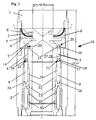
- FIG. 1 Conventional BOP systems as shown in Fig. 1 feature a pair of rams 32 located in horizontally opposed pockets located at 90 degree's to the vertical (well) bore or riser 11. To close the rams move towards one another meeting at the centre of the internal bore. Circa 40% of the ram length remains in each pocket to provide structural support resisting the pressure induced end load. Sealing integrity is achieved by a continuous elastomeric seal across the face of reach ram along the horizontal diameter of the ram and across the top o/d linking with the opposite horizontal leg, the sealing integrity being achieved by the contact of the elastomeric elements in the ram faces and the ram pocket.
- a major disadvantage of the system is that 50% of the total ram area is exposed to differential pressure when closed thus increasing effective sealing integrity.
- the rams are hydraulically actuated by pistons mounted on the axis of the ram and pocket which are connected to the outer face of each ram via an actuator rod.
- the area of this rod is exposed to well bore pressure and subsequently generates an axial outward (opening) force upon the system, which necessitates the provision of some form of locking system(wedgelocks) to avoid inadvertent opening of the rams in the advent of a hydraulic failure.
- a BOP system design requires a considerable width to i/d ratio to function efficiently, normally in the region of 8 to 10. It is therefor obvious despite the increased operational integrity provided by a BOP system that the external envelope precludes the use of this technology.
- Fig. 2 shows a longitudinal (vertical) cross sectional view of the lower part of a riser 11 with a horizontal production tree 12 and above the tree provided riser control device 10 according to the invention.
- the riser control device 10 is connected directly to the tree at the end of the riser below a (conventional) closing valve 13.
- Fig. 3 shows the riser control device 10 according to the invention in the normal operating (open) mode.
- the main body is made up of two sections, the upper housing 1 and the lower housing 2.
- the upper housing contains the rams 6 within cavity's 3 which are formed between the interface of the upper and lower housing.
- Machined in the lower face of each ram is a tee shaped slot 4, which runs parallel to the axis of the ram.
- a mating spigot 5 is formed on the upper section of the shear blade 7 which fits into the slot 4 in the rams lower face. This enable the blade to travel freely in relationship to the ram 6 for a predetermined linear distance.
- the distance of travel is determined by the length of the ram spigot (slot) and depth of the back plate attached to the ram.
- a flange is formed with a centre hole through the flange at 90 degree's to the ram and blade axis, The blade flange fits between two identical flanges 15 formed on the upper section of the translation beam 8 and is locked in position by inserting a retainer pin 16 into the bore of all three flanges.
- the lower end of the translation beam 8 is identical to the upper terminating in a dual flanged yoke 17 each with a centre hole at 90 degrees to the main axis of the beam. These flanges fit over a corresponding flange 18 formed on the upper section of the piston rod 9 and are attached by the insertion of an identical retainer pin 19 to that utilised in the upper yoke.
- This flange yoke assembly although identical to the upper assembly which allows the horizontal and vertical movement component to be transferred to a total horizontal movement enables the vertical movement of the piston rod 9 to be split into horizontal and vertical components.
- the combination of the two rotational hinges 20,21 at the opposite ends of the translation beam 8 enable the vertical movement of the piston rod 9 to be transferred to a total horizontal movement of the ram/bade assembly.
- the amount of vertical travel required to obtain the required horizontal component to fully open and close the rams 6 is dependant on both the length of the translation beam 8 and the initial angular offset of the rotational hinges 20,21. It should be noted that the longer the translation beam length the less the vertical travel required to obtain the horizontal component to obtain full closure.
- a significant advantage of this method of operating a ram 6 as opposed to a conventional linear system is that the travel of the ram is inverse to the vertical travel of the actuator therefore providing considerable mechanical advantage during the cutting and sealing section of the stoke resulting in improved cutting and sealing integrity.
- the actuation system for the ram/cutter 6,7 is operated hydraulically, but other forms of motive force can be utilised.
- the hydraulic actuation system is effectively a self contained unit which is assembled externally. This allows the system to be rapidly refurbished if required. Consisting of 8 major components which can be defined as the following: inner mandrel 22, piston rod 9, annular piston 23, balance piston 24, intermediate seal carrier 25, carrier retainer 26, mandrel retainer 27, and retainer lock ring 28.
- the actuator assembly is placed into the lower housing and locked insitu by the installation of the retainer lock ring into the internal thread of the lower housing 2.
- the installation of the assembly effectively forms two independent hydraulic chambers within the assembly.
- the upper chamber 29 is formed between the lower face of the inner mandrel 22 and the upper face of the annular piston 23.
- the lower chamber 30 is formed between the lower face of the annular piston 23 and the upper face of the intermediate seal carrier 25.
- Hydraulic conduits 31 located in the external wall of the lower housing 2 are through ported into the respective hydraulic chambers.
- the upper chamber 29 the opening conduit acts as the opening chamber, hydraulic pressure applied to the chamber 29 creates a differential force across the annular piston 23 creating a motive force urging the piston 23 to travel in the downwards direction.
- the piston rods 9 which are attached to the annular piston 23 by means of a thread 24 consequently travel downwards pulling the lower joint of the translation beam with it, which is transferred into horizontal movement of the shear blade 7 and ram 6 assembly urging each one to the open position.
- the lower chamber 30 which is fed by the hydraulic conduit acts as the closure system, hydraulic pressure applied via the conduit acts on the lower face of the annular piston 23 creating a differential pressure which translates to a motive force urging the piston 23 and consequently the piston rods 9 and lower joint 21 of the translation beam 8 upwards.
- the vertical movement is translated by the upper and lower joints of the translation beam to a true horizontal component therefore moving the blades and subsequently the rams to the closed position.
- Fig. 4 a), b) and c ) show sequence of the riser control device from starting to fully closed position.
- the closing operation is just initiated.
- Initial movement of the rams 6 is accomplished by means of spigots 27 provided on the translation beams 8.
- Fig. 4 b) shows control device in a position where the cutting knives 7 and rams 6 are in a mid-way cutting position
- Fig. 4 c) shows the rams 6 in a fully closed position where the resilient packing elements 31 are closing tightly against the remaining end of the production string (not shown) or the like.
- the invention as defined in the claims is not limited to use in connection with cutting and sealing off a drill string or riser, but may as well be used as a conventional closing valve, without the cutting knives 7.
Landscapes
- Geology (AREA)
- Life Sciences & Earth Sciences (AREA)
- Engineering & Computer Science (AREA)
- Mining & Mineral Resources (AREA)
- Environmental & Geological Engineering (AREA)
- Fluid Mechanics (AREA)
- Physics & Mathematics (AREA)
- General Life Sciences & Earth Sciences (AREA)
- Geochemistry & Mineralogy (AREA)
- Earth Drilling (AREA)
- Other Liquid Machine Or Engine Such As Wave Power Use (AREA)
- Advance Control (AREA)
- Forklifts And Lifting Vehicles (AREA)
- Motor Or Generator Current Collectors (AREA)
- Scissors And Nippers (AREA)
Claims (5)
- Dispositif de commande de colonne montante, destiné en particulier à être utilisé en relation avec des manchettes ou des arbres de production horizontaux (12) utilisés dans des installations pétrolières et gazières sous-marines,
caractérisé en ce qu'il est prévu, à l'intérieur d'une enveloppe (1, 2), une paire de mâchoires (6) mobiles radialement dans des directions opposées pour isoler le puits, et une paire de lames (7) mobiles radialement dans des directions opposées pour découper une tige d'intervention ou similaire, les mâchoires (6) et les lames (7) étant entraînées simultanément au moyen d'un actionneur vertical (8, 9, 23) contenu à l'intérieur de l'enveloppe (1, 2). - Dispositif de commande de colonne montante selon la revendication 1,
caractérisé en ce que l'actionneur se présente sous la forme d'un dispositif à piston annulaire entraîné hydrauliquement (23) / chambre annulaire (29, 30) prévu à l'intérieur de l'enveloppe (2), lequel, par l'intermédiaire de tiges de piston (14) et de poutres de translation (8), transforme le mouvement du piston (23) pour ouvrir ou fermer les mâchoires (6) et les lames (7). - Dispositif de commande de colonne montante selon les revendications 1 et 2,
caractérisé en ce que les lames (7) et les mâchoires (6) sont raccordées les unes aux autres, moyennant quoi le mouvement radial des lames (7) implique également un mouvement radial des mâchoires (6). - Dispositif de commande de colonne montante selon la revendication 3,
caractérisé en ce que les mâchoires (6) sont prévues au-dessus des lames (7), moyennant quoi l'interconnexion entre les mâchoires et les lames se fait sous la forme d'une fente (4) dans la face inférieure de chaque mâchoire (6) et d'un ergot correspondant (5) dans la partie supérieure de la lame (7). - Dispositif de commande de colonne montante selon la revendication 4,
caractérisé en ce que la fente (4) s'étend sur une distance parallèle à l'axe de la mâchoire (6), moyennant quoi la lame respective (7) se déplace librement par rapport à la mâchoire respective (6) sur la même distance.
Applications Claiming Priority (3)
| Application Number | Priority Date | Filing Date | Title |
|---|---|---|---|
| NO20020233A NO316189B1 (no) | 2002-01-16 | 2002-01-16 | Kontrollanordning for stigeror |
| NO20020233 | 2002-01-16 | ||
| PCT/NO2003/000011 WO2003060288A1 (fr) | 2002-01-16 | 2003-01-15 | Dispositif de commande de colonne montante |
Publications (2)
| Publication Number | Publication Date |
|---|---|
| EP1468165A1 EP1468165A1 (fr) | 2004-10-20 |
| EP1468165B1 true EP1468165B1 (fr) | 2010-01-06 |
Family
ID=19913225
Family Applications (1)
| Application Number | Title | Priority Date | Filing Date |
|---|---|---|---|
| EP03700628A Expired - Lifetime EP1468165B1 (fr) | 2002-01-16 | 2003-01-15 | Dispositif de commande de colonne montante |
Country Status (11)
| Country | Link |
|---|---|
| US (1) | US7389817B2 (fr) |
| EP (1) | EP1468165B1 (fr) |
| CN (1) | CN1633541B (fr) |
| AT (1) | ATE454529T1 (fr) |
| AU (1) | AU2003201784A1 (fr) |
| BR (1) | BR0306940B1 (fr) |
| CA (1) | CA2474028C (fr) |
| DE (1) | DE60330838D1 (fr) |
| DK (1) | DK1468165T3 (fr) |
| NO (1) | NO316189B1 (fr) |
| WO (1) | WO2003060288A1 (fr) |
Families Citing this family (23)
| Publication number | Priority date | Publication date | Assignee | Title |
|---|---|---|---|---|
| GB0410198D0 (en) * | 2004-05-07 | 2004-06-09 | Enovate Systems Ltd | Wellbore control device |
| US7584797B2 (en) * | 2006-04-04 | 2009-09-08 | Stinger Wellhead Protection, Inc. | Method of subsurface lubrication to facilitate well completion, re-completion and workover |
| US8720564B2 (en) | 2006-04-25 | 2014-05-13 | National Oilwell Varco, L.P. | Tubular severing system and method of using same |
| US8424607B2 (en) | 2006-04-25 | 2013-04-23 | National Oilwell Varco, L.P. | System and method for severing a tubular |
| US7367396B2 (en) | 2006-04-25 | 2008-05-06 | Varco I/P, Inc. | Blowout preventers and methods of use |
| US8720565B2 (en) | 2006-04-25 | 2014-05-13 | National Oilwell Varco, L.P. | Tubular severing system and method of using same |
| US8844898B2 (en) | 2009-03-31 | 2014-09-30 | National Oilwell Varco, L.P. | Blowout preventer with ram socketing |
| RU2559238C2 (ru) * | 2010-05-28 | 2015-08-10 | НЭШНЛ ОЙЛВЕЛЛ ВАРКО, Эл.Пи. | Система отрезания трубного изделия и способ ее использования |
| US8540017B2 (en) | 2010-07-19 | 2013-09-24 | National Oilwell Varco, L.P. | Method and system for sealing a wellbore |
| US8544538B2 (en) | 2010-07-19 | 2013-10-01 | National Oilwell Varco, L.P. | System and method for sealing a wellbore |
| WO2012011269A1 (fr) | 2010-07-20 | 2012-01-26 | 株式会社 京都医療設計 | Elément de couverture de stent et dispositif de stent |
| US8807219B2 (en) | 2010-09-29 | 2014-08-19 | National Oilwell Varco, L.P. | Blowout preventer blade assembly and method of using same |
| US8662183B1 (en) * | 2011-02-12 | 2014-03-04 | Louis P. Vickio, Jr. | Blow out preventer |
| KR20150092371A (ko) | 2011-03-09 | 2015-08-12 | 내셔널 오일웰 바르코 엘.피. | 유정 보어를 밀봉하기 위한 방법 및 장치 |
| GB2497089A (en) * | 2011-11-29 | 2013-06-05 | Dpir Ltd | Shear apparatus with a guide member |
| US9388657B2 (en) * | 2012-07-13 | 2016-07-12 | Clinton D. Nelson | Automatic annular blow-out preventer |
| BR112015020108B1 (pt) | 2013-02-21 | 2021-11-09 | National Oilwell Varco, L.P. | Unidade de controlador preventivo de erupção, e, método de monitoramento de um controlador preventivo de erupção |
| US11136849B2 (en) * | 2019-11-05 | 2021-10-05 | Saudi Arabian Oil Company | Dual string fluid management devices for oil and gas applications |
| US12054999B2 (en) | 2021-03-01 | 2024-08-06 | Saudi Arabian Oil Company | Maintaining and inspecting a wellbore |
| US11905791B2 (en) | 2021-08-18 | 2024-02-20 | Saudi Arabian Oil Company | Float valve for drilling and workover operations |
| US11913298B2 (en) | 2021-10-25 | 2024-02-27 | Saudi Arabian Oil Company | Downhole milling system |
| US12276190B2 (en) | 2022-02-16 | 2025-04-15 | Saudi Arabian Oil Company | Ultrasonic flow check systems for wellbores |
| US12146377B1 (en) * | 2023-06-28 | 2024-11-19 | Schlumberger Technology Corporation | Electric annular system and method for use in blowout preventer |
Family Cites Families (24)
| Publication number | Priority date | Publication date | Assignee | Title |
|---|---|---|---|---|
| US1839394A (en) * | 1929-10-28 | 1932-01-05 | Melvin C Inge | Blow-out preventer or control head |
| US2812197A (en) * | 1955-08-16 | 1957-11-05 | Shaffer Tool Works | Toggle packer, well head preventer |
| US2919111A (en) * | 1955-12-30 | 1959-12-29 | California Research Corp | Shearing device and method for use in well drilling |
| US2969838A (en) * | 1956-07-23 | 1961-01-31 | Shaffer Tool Works | Combination shearing and shut-off ram |
| US3684008A (en) * | 1970-07-16 | 1972-08-15 | Henry U Garrett | Well bore blocking means and method |
| US3720260A (en) * | 1971-01-28 | 1973-03-13 | J Duck | Method and apparatus for controlling an offshore well |
| US3870098A (en) * | 1973-08-13 | 1975-03-11 | William T Houston | Remotely controllable subterranean oil well valve |
| US4095805A (en) * | 1976-10-15 | 1978-06-20 | Cameron Iron Works, Inc. | Annular blowout preventer |
| US4215749A (en) * | 1979-02-05 | 1980-08-05 | Acf Industries, Incorporated | Gate valve for shearing workover lines to permit shutting in of a well |
| US4240503A (en) * | 1979-05-01 | 1980-12-23 | Hydril Company | Blowout preventer shearing and sealing rams |
| US4313496A (en) * | 1980-04-22 | 1982-02-02 | Cameron Iron Works, Inc. | Wellhead shearing apparatus |
| US4323117A (en) * | 1980-04-23 | 1982-04-06 | Laurance Pierce | Method and means for emergency shearing and sealing of well casing |
| US4347898A (en) * | 1980-11-06 | 1982-09-07 | Cameron Iron Works, Inc. | Shear ram blowout preventer |
| US4441742A (en) * | 1981-12-04 | 1984-04-10 | Armco Inc. | Connectors for securing members together under large clamping |
| US4508313A (en) * | 1982-12-02 | 1985-04-02 | Koomey Blowout Preventers, Inc. | Valves |
| US4580626A (en) * | 1982-12-02 | 1986-04-08 | Koomey Blowout Preventers, Inc. | Blowout preventers having shear rams |
| US4987956A (en) * | 1989-08-30 | 1991-01-29 | Asger Hansen | Apparatus for use in drilling a well at an offshore location |
| US5287920A (en) * | 1992-06-16 | 1994-02-22 | Terrell Donna K | Large head downhole chemical cutting tool |
| US5360061A (en) * | 1992-10-14 | 1994-11-01 | Womble Lee M | Blowout preventer with tubing shear rams |
| CA2088794A1 (fr) | 1993-02-04 | 1994-08-05 | Dieter Trosin | Obturateur anti-eruption portatif |
| US5400857A (en) * | 1993-12-08 | 1995-03-28 | Varco Shaffer, Inc. | Oilfield tubular shear ram and method for blowout prevention |
| US5515916A (en) * | 1995-03-03 | 1996-05-14 | Stewart & Stevenson Services, Inc. | Blowout preventer |
| US6244336B1 (en) * | 2000-03-07 | 2001-06-12 | Cooper Cameron Corporation | Double shearing rams for ram type blowout preventer |
| US6601650B2 (en) * | 2001-08-09 | 2003-08-05 | Worldwide Oilfield Machine, Inc. | Method and apparatus for replacing BOP with gate valve |
-
2002
- 2002-01-16 NO NO20020233A patent/NO316189B1/no not_active IP Right Cessation
-
2003
- 2003-01-15 DE DE60330838T patent/DE60330838D1/de not_active Expired - Lifetime
- 2003-01-15 AT AT03700628T patent/ATE454529T1/de not_active IP Right Cessation
- 2003-01-15 EP EP03700628A patent/EP1468165B1/fr not_active Expired - Lifetime
- 2003-01-15 WO PCT/NO2003/000011 patent/WO2003060288A1/fr not_active Ceased
- 2003-01-15 DK DK03700628.5T patent/DK1468165T3/da active
- 2003-01-15 CA CA2474028A patent/CA2474028C/fr not_active Expired - Lifetime
- 2003-01-15 BR BRPI0306940-0A patent/BR0306940B1/pt active IP Right Grant
- 2003-01-15 US US10/501,325 patent/US7389817B2/en not_active Expired - Lifetime
- 2003-01-15 AU AU2003201784A patent/AU2003201784A1/en not_active Abandoned
- 2003-01-15 CN CN038040700A patent/CN1633541B/zh not_active Expired - Lifetime
Also Published As
| Publication number | Publication date |
|---|---|
| WO2003060288A1 (fr) | 2003-07-24 |
| EP1468165A1 (fr) | 2004-10-20 |
| NO20020233L (no) | 2003-07-17 |
| US7389817B2 (en) | 2008-06-24 |
| ATE454529T1 (de) | 2010-01-15 |
| BR0306940B1 (pt) | 2012-06-12 |
| CA2474028C (fr) | 2010-10-19 |
| BR0306940A (pt) | 2004-12-14 |
| CN1633541A (zh) | 2005-06-29 |
| AU2003201784A1 (en) | 2003-07-30 |
| CA2474028A1 (fr) | 2003-07-24 |
| DK1468165T3 (da) | 2010-03-15 |
| DE60330838D1 (de) | 2010-02-25 |
| NO20020233D0 (no) | 2002-01-16 |
| NO316189B1 (no) | 2003-12-22 |
| CN1633541B (zh) | 2010-10-06 |
| US20050051339A1 (en) | 2005-03-10 |
Similar Documents
| Publication | Publication Date | Title |
|---|---|---|
| EP1468165B1 (fr) | Dispositif de commande de colonne montante | |
| US9085951B2 (en) | Subsea connection apparatus for a surface blowout preventer stack | |
| EP2834448B1 (fr) | Connecteur de site de forage à élément d'étanchéité flottant et son procédé d'utilisation | |
| US8066075B2 (en) | Completion suspension valve system | |
| US11085248B2 (en) | Centralizer | |
| AU697126B2 (en) | Simplified xmas tree using sub-sea test tree | |
| US3222088A (en) | Wellhead connector with diagonally directed latches | |
| US9534466B2 (en) | Cap system for subsea equipment | |
| GB2286840A (en) | Safety valve for horizontal tree | |
| EP0124601A1 (fr) | Procede et appareil a vanne de securite | |
| US9194202B2 (en) | Fishing tool for drill pipe | |
| EP2028340A1 (fr) | Système de champ pétrolifère pour TTRP | |
| WO2020219412A1 (fr) | Mâchoire à cisaillement de bloc d'obturation de puits | |
| CN102536150A (zh) | 紧急海底井口关闭装置 | |
| US6231265B1 (en) | Self-aligning subsea latch mechanism | |
| WO2016164256A1 (fr) | Mâchoire cisaillante et bielle d'obturateur anti-éruption à haute résistance | |
| GB2493175A (en) | A ball valve having a recessed cutting area | |
| CN108119078B (zh) | 用于加压流体流动路径的连接件 | |
| Adam et al. | HT Technology-A1l-meta Sealing Answers Safety & Environmental Concerns | |
| WO2014058423A1 (fr) | Outil de repêchage pour tube de forage | |
| US20250305385A1 (en) | Rotary actuated shear and seal valve | |
| Olijnik et al. | New design of a guidelineless horizontal tree for deepwater ESP wells | |
| GB2443109A (en) | Flapper valve assembly with bi-directional sealing |
Legal Events
| Date | Code | Title | Description |
|---|---|---|---|
| PUAI | Public reference made under article 153(3) epc to a published international application that has entered the european phase |
Free format text: ORIGINAL CODE: 0009012 |
|
| 17P | Request for examination filed |
Effective date: 20040816 |
|
| AK | Designated contracting states |
Kind code of ref document: A1 Designated state(s): AT BE BG CH CY CZ DE DK EE ES FI FR GB GR HU IE IT LI LU MC NL PT SE SI SK TR |
|
| AX | Request for extension of the european patent |
Extension state: AL LT LV MK RO |
|
| 17Q | First examination report despatched |
Effective date: 20070130 |
|
| GRAP | Despatch of communication of intention to grant a patent |
Free format text: ORIGINAL CODE: EPIDOSNIGR1 |
|
| GRAS | Grant fee paid |
Free format text: ORIGINAL CODE: EPIDOSNIGR3 |
|
| GRAA | (expected) grant |
Free format text: ORIGINAL CODE: 0009210 |
|
| AK | Designated contracting states |
Kind code of ref document: B1 Designated state(s): AT BE BG CH CY CZ DE DK EE ES FI FR GB GR HU IE IT LI LU MC NL PT SE SI SK TR |
|
| REG | Reference to a national code |
Ref country code: GB Ref legal event code: FG4D |
|
| REG | Reference to a national code |
Ref country code: CH Ref legal event code: EP |
|
| REG | Reference to a national code |
Ref country code: IE Ref legal event code: FG4D |
|
| REF | Corresponds to: |
Ref document number: 60330838 Country of ref document: DE Date of ref document: 20100225 Kind code of ref document: P |
|
| REG | Reference to a national code |
Ref country code: DK Ref legal event code: T3 |
|
| REG | Reference to a national code |
Ref country code: NL Ref legal event code: T3 |
|
| PG25 | Lapsed in a contracting state [announced via postgrant information from national office to epo] |
Ref country code: SI Free format text: LAPSE BECAUSE OF FAILURE TO SUBMIT A TRANSLATION OF THE DESCRIPTION OR TO PAY THE FEE WITHIN THE PRESCRIBED TIME-LIMIT Effective date: 20100106 |
|
| PG25 | Lapsed in a contracting state [announced via postgrant information from national office to epo] |
Ref country code: AT Free format text: LAPSE BECAUSE OF FAILURE TO SUBMIT A TRANSLATION OF THE DESCRIPTION OR TO PAY THE FEE WITHIN THE PRESCRIBED TIME-LIMIT Effective date: 20100106 |
|
| PG25 | Lapsed in a contracting state [announced via postgrant information from national office to epo] |
Ref country code: PT Free format text: LAPSE BECAUSE OF FAILURE TO SUBMIT A TRANSLATION OF THE DESCRIPTION OR TO PAY THE FEE WITHIN THE PRESCRIBED TIME-LIMIT Effective date: 20100506 Ref country code: ES Free format text: LAPSE BECAUSE OF FAILURE TO SUBMIT A TRANSLATION OF THE DESCRIPTION OR TO PAY THE FEE WITHIN THE PRESCRIBED TIME-LIMIT Effective date: 20100417 |
|
| PG25 | Lapsed in a contracting state [announced via postgrant information from national office to epo] |
Ref country code: MC Free format text: LAPSE BECAUSE OF NON-PAYMENT OF DUE FEES Effective date: 20100131 Ref country code: FI Free format text: LAPSE BECAUSE OF FAILURE TO SUBMIT A TRANSLATION OF THE DESCRIPTION OR TO PAY THE FEE WITHIN THE PRESCRIBED TIME-LIMIT Effective date: 20100106 |
|
| REG | Reference to a national code |
Ref country code: CH Ref legal event code: PL |
|
| PG25 | Lapsed in a contracting state [announced via postgrant information from national office to epo] |
Ref country code: EE Free format text: LAPSE BECAUSE OF FAILURE TO SUBMIT A TRANSLATION OF THE DESCRIPTION OR TO PAY THE FEE WITHIN THE PRESCRIBED TIME-LIMIT Effective date: 20100106 Ref country code: SE Free format text: LAPSE BECAUSE OF FAILURE TO SUBMIT A TRANSLATION OF THE DESCRIPTION OR TO PAY THE FEE WITHIN THE PRESCRIBED TIME-LIMIT Effective date: 20100106 Ref country code: LI Free format text: LAPSE BECAUSE OF NON-PAYMENT OF DUE FEES Effective date: 20100131 Ref country code: GR Free format text: LAPSE BECAUSE OF FAILURE TO SUBMIT A TRANSLATION OF THE DESCRIPTION OR TO PAY THE FEE WITHIN THE PRESCRIBED TIME-LIMIT Effective date: 20100407 Ref country code: BE Free format text: LAPSE BECAUSE OF FAILURE TO SUBMIT A TRANSLATION OF THE DESCRIPTION OR TO PAY THE FEE WITHIN THE PRESCRIBED TIME-LIMIT Effective date: 20100106 Ref country code: CH Free format text: LAPSE BECAUSE OF NON-PAYMENT OF DUE FEES Effective date: 20100131 Ref country code: CY Free format text: LAPSE BECAUSE OF FAILURE TO SUBMIT A TRANSLATION OF THE DESCRIPTION OR TO PAY THE FEE WITHIN THE PRESCRIBED TIME-LIMIT Effective date: 20100106 |
|
| PLBE | No opposition filed within time limit |
Free format text: ORIGINAL CODE: 0009261 |
|
| STAA | Information on the status of an ep patent application or granted ep patent |
Free format text: STATUS: NO OPPOSITION FILED WITHIN TIME LIMIT |
|
| PG25 | Lapsed in a contracting state [announced via postgrant information from national office to epo] |
Ref country code: CZ Free format text: LAPSE BECAUSE OF FAILURE TO SUBMIT A TRANSLATION OF THE DESCRIPTION OR TO PAY THE FEE WITHIN THE PRESCRIBED TIME-LIMIT Effective date: 20100106 Ref country code: SK Free format text: LAPSE BECAUSE OF FAILURE TO SUBMIT A TRANSLATION OF THE DESCRIPTION OR TO PAY THE FEE WITHIN THE PRESCRIBED TIME-LIMIT Effective date: 20100106 Ref country code: BG Free format text: LAPSE BECAUSE OF FAILURE TO SUBMIT A TRANSLATION OF THE DESCRIPTION OR TO PAY THE FEE WITHIN THE PRESCRIBED TIME-LIMIT Effective date: 20100406 |
|
| 26N | No opposition filed |
Effective date: 20101007 |
|
| PG25 | Lapsed in a contracting state [announced via postgrant information from national office to epo] |
Ref country code: IE Free format text: LAPSE BECAUSE OF NON-PAYMENT OF DUE FEES Effective date: 20100115 |
|
| PG25 | Lapsed in a contracting state [announced via postgrant information from national office to epo] |
Ref country code: HU Free format text: LAPSE BECAUSE OF FAILURE TO SUBMIT A TRANSLATION OF THE DESCRIPTION OR TO PAY THE FEE WITHIN THE PRESCRIBED TIME-LIMIT Effective date: 20100707 Ref country code: LU Free format text: LAPSE BECAUSE OF NON-PAYMENT OF DUE FEES Effective date: 20100115 |
|
| PG25 | Lapsed in a contracting state [announced via postgrant information from national office to epo] |
Ref country code: TR Free format text: LAPSE BECAUSE OF FAILURE TO SUBMIT A TRANSLATION OF THE DESCRIPTION OR TO PAY THE FEE WITHIN THE PRESCRIBED TIME-LIMIT Effective date: 20100106 |
|
| REG | Reference to a national code |
Ref country code: FR Ref legal event code: TP Owner name: STATOIL PETROLEUM AS, NO Effective date: 20130704 |
|
| REG | Reference to a national code |
Ref country code: DE Ref legal event code: R082 Ref document number: 60330838 Country of ref document: DE Representative=s name: EISENFUEHR, SPEISER & PARTNER, DE |
|
| REG | Reference to a national code |
Ref country code: GB Ref legal event code: 732E Free format text: REGISTERED BETWEEN 20130815 AND 20130821 |
|
| REG | Reference to a national code |
Ref country code: DE Ref legal event code: R082 Ref document number: 60330838 Country of ref document: DE Representative=s name: EISENFUEHR SPEISER PATENTANWAELTE RECHTSANWAEL, DE Effective date: 20130909 Ref country code: DE Ref legal event code: R081 Ref document number: 60330838 Country of ref document: DE Owner name: STATOIL PETROLEUM AS, NO Free format text: FORMER OWNER: NORSK HYDRO ASA, OSLO, NO Effective date: 20130909 Ref country code: DE Ref legal event code: R081 Ref document number: 60330838 Country of ref document: DE Owner name: STATOIL PETROLEUM AS, NO Free format text: FORMER OWNER: STATOIL ASA, STAVANGER, NO Effective date: 20130909 Ref country code: DE Ref legal event code: R082 Ref document number: 60330838 Country of ref document: DE Representative=s name: EISENFUEHR, SPEISER & PARTNER, DE Effective date: 20130909 |
|
| REG | Reference to a national code |
Ref country code: NL Ref legal event code: SD Effective date: 20131220 |
|
| REG | Reference to a national code |
Ref country code: FR Ref legal event code: PLFP Year of fee payment: 13 |
|
| REG | Reference to a national code |
Ref country code: FR Ref legal event code: PLFP Year of fee payment: 14 |
|
| REG | Reference to a national code |
Ref country code: FR Ref legal event code: PLFP Year of fee payment: 15 |
|
| REG | Reference to a national code |
Ref country code: FR Ref legal event code: PLFP Year of fee payment: 16 |
|
| PGFP | Annual fee paid to national office [announced via postgrant information from national office to epo] |
Ref country code: GB Payment date: 20220125 Year of fee payment: 20 Ref country code: DK Payment date: 20220124 Year of fee payment: 20 Ref country code: DE Payment date: 20220124 Year of fee payment: 20 |
|
| PGFP | Annual fee paid to national office [announced via postgrant information from national office to epo] |
Ref country code: NL Payment date: 20220131 Year of fee payment: 20 Ref country code: IT Payment date: 20220124 Year of fee payment: 20 Ref country code: FR Payment date: 20220120 Year of fee payment: 20 |
|
| REG | Reference to a national code |
Ref country code: DE Ref legal event code: R071 Ref document number: 60330838 Country of ref document: DE |
|
| REG | Reference to a national code |
Ref country code: DK Ref legal event code: EUP Expiry date: 20230115 |
|
| REG | Reference to a national code |
Ref country code: NL Ref legal event code: MK Effective date: 20230114 |
|
| REG | Reference to a national code |
Ref country code: GB Ref legal event code: PE20 Expiry date: 20230114 |
|
| PG25 | Lapsed in a contracting state [announced via postgrant information from national office to epo] |
Ref country code: GB Free format text: LAPSE BECAUSE OF EXPIRATION OF PROTECTION Effective date: 20230114 |