EP1468219B1 - Verbindung von rohren mit innenkleidung - Google Patents
Verbindung von rohren mit innenkleidung Download PDFInfo
- Publication number
- EP1468219B1 EP1468219B1 EP03700927A EP03700927A EP1468219B1 EP 1468219 B1 EP1468219 B1 EP 1468219B1 EP 03700927 A EP03700927 A EP 03700927A EP 03700927 A EP03700927 A EP 03700927A EP 1468219 B1 EP1468219 B1 EP 1468219B1
- Authority
- EP
- European Patent Office
- Prior art keywords
- pipe
- liner
- insert
- tubular member
- insulating sleeve
- Prior art date
- Legal status (The legal status is an assumption and is not a legal conclusion. Google has not performed a legal analysis and makes no representation as to the accuracy of the status listed.)
- Expired - Lifetime
Links
- 239000000463 material Substances 0.000 claims abstract description 16
- 239000011810 insulating material Substances 0.000 claims abstract description 6
- 239000004033 plastic Substances 0.000 claims abstract description 3
- 229920003023 plastic Polymers 0.000 claims abstract description 3
- 239000003779 heat-resistant material Substances 0.000 claims abstract 2
- 238000000034 method Methods 0.000 claims description 17
- 238000003466 welding Methods 0.000 claims description 11
- 239000002184 metal Substances 0.000 claims description 7
- 239000000919 ceramic Substances 0.000 claims description 6
- 239000003822 epoxy resin Substances 0.000 claims description 4
- 239000012774 insulation material Substances 0.000 claims description 4
- 229920000647 polyepoxide Polymers 0.000 claims description 4
- 230000001154 acute effect Effects 0.000 claims description 3
- 239000006260 foam Substances 0.000 claims description 2
- 239000007789 gas Substances 0.000 claims 1
- 229920001903 high density polyethylene Polymers 0.000 abstract description 9
- 230000007797 corrosion Effects 0.000 description 3
- 238000005260 corrosion Methods 0.000 description 3
- 229910000831 Steel Inorganic materials 0.000 description 2
- 239000011324 bead Substances 0.000 description 2
- 239000012530 fluid Substances 0.000 description 2
- 230000004927 fusion Effects 0.000 description 2
- 239000004700 high-density polyethylene Substances 0.000 description 2
- 239000007769 metal material Substances 0.000 description 2
- 239000010959 steel Substances 0.000 description 2
- 229910000975 Carbon steel Inorganic materials 0.000 description 1
- 239000004952 Polyamide Substances 0.000 description 1
- 239000004959 Rilsan Substances 0.000 description 1
- 238000004873 anchoring Methods 0.000 description 1
- 238000005452 bending Methods 0.000 description 1
- 239000010962 carbon steel Substances 0.000 description 1
- 230000006835 compression Effects 0.000 description 1
- 238000007906 compression Methods 0.000 description 1
- 238000010276 construction Methods 0.000 description 1
- 229920006332 epoxy adhesive Polymers 0.000 description 1
- 229920002313 fluoropolymer Polymers 0.000 description 1
- 230000000977 initiatory effect Effects 0.000 description 1
- 238000009434 installation Methods 0.000 description 1
- 238000009413 insulation Methods 0.000 description 1
- 238000012986 modification Methods 0.000 description 1
- 230000004048 modification Effects 0.000 description 1
- 230000002093 peripheral effect Effects 0.000 description 1
- 239000012466 permeate Substances 0.000 description 1
- 229920002647 polyamide Polymers 0.000 description 1
- 239000010935 stainless steel Substances 0.000 description 1
- 229910001220 stainless steel Inorganic materials 0.000 description 1
- 239000002937 thermal insulation foam Substances 0.000 description 1
- 229920001169 thermoplastic Polymers 0.000 description 1
- 239000012815 thermoplastic material Substances 0.000 description 1
- 239000004416 thermosoftening plastic Substances 0.000 description 1
Images



Classifications
-
- F—MECHANICAL ENGINEERING; LIGHTING; HEATING; WEAPONS; BLASTING
- F16—ENGINEERING ELEMENTS AND UNITS; GENERAL MEASURES FOR PRODUCING AND MAINTAINING EFFECTIVE FUNCTIONING OF MACHINES OR INSTALLATIONS; THERMAL INSULATION IN GENERAL
- F16L—PIPES; JOINTS OR FITTINGS FOR PIPES; SUPPORTS FOR PIPES, CABLES OR PROTECTIVE TUBING; MEANS FOR THERMAL INSULATION IN GENERAL
- F16L13/00—Non-disconnectable pipe joints, e.g. soldered, adhesive, or caulked joints
- F16L13/02—Welded joints
- F16L13/0254—Welded joints the pipes having an internal or external coating
- F16L13/0263—Welded joints the pipes having an internal or external coating having an internal coating
-
- Y—GENERAL TAGGING OF NEW TECHNOLOGICAL DEVELOPMENTS; GENERAL TAGGING OF CROSS-SECTIONAL TECHNOLOGIES SPANNING OVER SEVERAL SECTIONS OF THE IPC; TECHNICAL SUBJECTS COVERED BY FORMER USPC CROSS-REFERENCE ART COLLECTIONS [XRACs] AND DIGESTS
- Y10—TECHNICAL SUBJECTS COVERED BY FORMER USPC
- Y10T—TECHNICAL SUBJECTS COVERED BY FORMER US CLASSIFICATION
- Y10T29/00—Metal working
- Y10T29/53—Means to assemble or disassemble
- Y10T29/53909—Means comprising hand manipulatable tool
- Y10T29/53913—Aligner or center
- Y10T29/53917—Tube with tube
Definitions
- This invention relates to pipelines which are lined with a plastics material.
- Pipelines are constructed by first forming lengths or "stalks" of pipe, and subsequently joining the stalks together.
- the stalks may be joined in the field for a land-based pipeline.
- the stalks may be joined on a lay barge, or may be joined while the pipe is being reeled onto a reel laying vessel.
- a metal, typically a steel, pipeline must be lined with a plastic liner in order to prevent corrosion of the internal surface of the pipe because of the nature of the fluid to be transported and on conditions of use such as pressure and temperature.
- a plastic liner When connecting stalks of lined pipe together, it is necessary to ensure that the corrosion protection provided by the liner is continuous across the connection.
- plastic liners which are provided on their outer faces with continuous longitudinal grooves. This is done because gas within the transported fluid can permeate through the liner and accumulate at the liner/pipe interface. The grooves allow the gas to travel along the interface to some point where a gas draw-off is provided through the pipe. Prior art methods of joining lined pipe stalks do not permit such grooves or equivalent gas seepage paths to extend across the join.
- US 5,998,691 shows a method of connecting stalks of lined pipe which makes use of pup pieces welded within the ends of the pipe stalks. This method requires continuous corrosion-resistant welds to be made between the pipes and the pup pieces. This method is complicated to implement and takes time. Also, it cannot provide gas drainage grooves extending across the join.
- EP 0,366,299 shows an arrangement using a thermoplastic insert which carries a ceramic ring on top of which welding is performed, insulation being provided between the ceramic ring and the thermoplastic material.
- the arrangement disclosed in this document has the disadvantage that the location of the ceramic ring can vary; this is because the liners and the insert are typically joined under tension, and when abutting the external pipe there can be no assurance that the liner has kept its position. Also, during service the liner can move within the pipe. It is therefore difficult to ensure that the ring is positioned under the pipe welding location in all circumstances. Also, this prior art considerably reduces the size of the internal bore while keeping the thickness of the liner at the connection, and it cannot be implemented with a grooved liner.
- US 5 104 152 shows an insert similar to the insert used in claim 1 and 9.
- a primary object of the present invention is to provide a method of joining lined pipelines, using an adequate insert, which give a simple and quick connection with reduced risk of damage to the liner.
- Preferred forms of the invention are also capable of providing connection between grooved liners.
- the present invention provides a pipe joint connecting a first pipe and a second pipe comprising an insert as defined in claim 1.
- the invention further provides a method of connecting a first pipe containing a first liner to a second pipe containing a second liner, the method comprising the steps of:
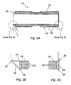
- an insert 10 for use in joining two lengths of pipe comprises an inner tubular member 12 having a central recess in which is received a sleeve 14.
- the sleeve 14 in turn has a peripheral annular groove in which is received a non-metallic heat resistant element such as a ceramic ring 16.
- the insert 10 is intended for use in joining pipes having plastic liners, for example of high density polyethylene (HDPE) or fluorocarbon polymer, and the tubular member 12 is formed of a material matching the liners.
- One suitable material for the tubular member 12 is "Rilsan" polyamide by Atofina.
- the ceramic ring may, for example, be of Gullco "Katbac" material.
- the sleeve 14 comprises a thermal insulation material 22 enclosed within a sheath 24.
- the insulation material is preferably a compressible material, for example a compressible microporous or insulation foam; one example is a microporous foam having a density of 160-210 kg/m 3 .
- the sheath 24 in this embodiment is fabricated from stainless steel 1 mm thick, the parts being brazed at the locations identified at 26. Other metallic materials, for example carbon steel, or non-metallic materials may be used.
- the sheath is sufficiently thin that in use of the eventual pipeline the working pressure will compress the sheath 24 and insulating material 22, thereby reducing the extent to which the insert 10 reduces the working bore of the pipeline. Such compression is assisted by the provision of end clearances 28 within the sheath 24.
- the sheath 24 can be designed to withstand the working pressure and so it can be fabricated of high strength steel for example.
- the internal diameter of the bore of the pipeline will experience a reduction through the connection but the risk of damaging the tubular body 12 of the insert 10 due to the collapse of the sleeve 14 will be reduced or eliminated.
- one end of the sleeve 14 has the sheath 24 formed at 30 to present an acute angle ⁇ which may typically be 45°.
- the tubular member 12 has a correspondingly angled annular recess 32 in which the end 30 of the sleeve 14 is received.
- the sheath 24 allows the sleeve 14 to be bonded to the host pipe during the connection process, preferably by use of an epoxy adhesive.
- the use of bonding obviates the need for welding the sleeve in place, thus reducing the risk of introducing a fatigue initiation point. This bonding ensures that the heat resistant element is placed at the correct location during external pipe welding operations.
- the insert is anchored in the host pipeline at each connection location.
- the acute angle ⁇ assists in anchoring the liner during installation and in service by reducing the risk of the liner pulling through the insulating sleeve.
- the insert 10 may suitably be assembled by forming the tubular member 12 in two parts which are joined by fusion along the line 18 after the sleeve 14 and ring 16 have been positioned.
- the tubular member 12 is formed with grooves, in this embodiment six grooves 20, which extend along its length and beneath the sleeve 14.
- the provision of the grooves 20 allows the insert 10, when used with grooved pipe liners, to provide a gas drain path extending through the connection.
- the grooves 20 may be omitted, or may be replaced with longitudinal bores extending within the insert body which may be advantageous in reducing strains on the insert material.
- the sheath 24 is useful in protecting the grooves 20 from the insulation material 22. In this case, the sleeve 14 and its sheath 24 can be calculated to withstand the bore working pressure in order to protect the grooves 20.
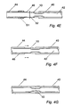
- Fig. 4 shows one example of the method of the invention, in which the insert 10 is used in joining a first pipe stalk 40 having a plastic liner 42 to a second pipe stalk 44 having a plastic liner 46.
- the method example will be described herein with reference to use with a reel pipelaying ship, but it will be apparent that a similar method may be used in other applications.
- Figs. 4A-4C The first stages shown in Figs. 4A-4C are carried out at the spoolbase where the pipe stalk 40 has been prepared by welding together lengths of pipe and pulling in the liner 42. The liner 42 is pulled through the stalk ( Fig. 4A ) and then the tension released.
- the liner 42 is then extended under tension and released to establish where a cut must be made to produce a cut end at a desired location within the pipe stalk 40. Then, as seen in Fig. 4B , the liner 42 is extended by the required amount and clamped in position by an internal clamp 48 and the liner 42 is cut at 50.
- the insert 10 is then positioned abutting the cut liner 42 ( Fig. 4C ), and the end of the member 12 is fused to the cut end of the liner 42.
- Epoxy resin is applied to the end of the sleeve 14 facing the pipe stalk 40.
- the clamp 48 is then released, allowing the liner 42 to retract drawing the insert 10 partially within the first pipe stalk 40, and the epoxy resin bonds the insert in position within the pipe stalk 40.
- the pipe stalk 40 is now reeled onto the reel vessel with the end illustrated extending from the reel.
- Fig. 4D shows the leading end of the next pipe stalk 44.
- the liner 46 is extended under tension and released to allow the position for the required cut to be established. Then, the liner 46 is extended and clamped by an external clamp 51, and the liner 46 is cut at 52 such that, on release, the cut end will lie at 54 within the pipe stalk 44.
- the next steps will usually be performed in the tie-in shed adjacent the vessel as the stalk 44 arrives.
- the liner 46 is extended and held by the clamp 51 ( Fig. 4E ) while the liner 46 is aligned with the insert 10 and the liner 46 is fused to the tubular member 12 at 52.
- the clamp 51 is removed and the stalks 40 and 44 are closed together ( Fig. 4F ) as the liner retracts.
- a preferred feature of the insert 10 is that it is designed to partially collapse or compress under the working pressure of the eventual pipeline, due to the design of the insulating sleeve.
- the exemplary construction detailed above is suitable for this purpose in a typical subsea pipeline.
- the encapsulated insulating material collapses, allowing the body of the insert to move radially outward. This feature minimises the reduction of flow area in the pipeline caused by the insert.
- the metal sheath will prevent the grooves being obstructed by the insulating material.
- the present invention also makes it possible to provide a join between pipe stalks which has bending characteristics similar to those of the pipe.
- the sleeve could be only partially, as opposed to entirely, encased in metal but it is desirable to provide a metal portion at least in an area suitable for bonding to the pipe. This could be done by having metal covering to the ends and the outer surface only, or to the ends, the inner surface and end portions of the outer surface. An inner metallic portion is useful in maintaining the grooves open.
Landscapes
- Engineering & Computer Science (AREA)
- General Engineering & Computer Science (AREA)
- Mechanical Engineering (AREA)
- Lining Or Joining Of Plastics Or The Like (AREA)
- Thermal Insulation (AREA)
- Handcart (AREA)
Claims (12)
- Eine Rohrverbindung, die ein erstes Rohr (40) mit einer ersten Auskleidung (42) und ein zweites Rohr (44) mit einer zweiten Auskleidung (46) beinhaltet, wobei die Rohrverbindung das erste Rohr (40) und das zweite Rohr (44) verbindet und zwischen dem ersten Rohr (40) und dem zweiten Rohr (44) einen Einsatz (10) mit einem äußeren Durchmesser, der den inneren Durchmessern des ersten Rohrs (40) und zweiten Rohrs (44) entspricht, beinhaltet, wobei der Einsatz (10) Folgendes beinhaltet:ein inneres röhrenförmiges Element (12), welches(i) aus einem Kunststoffmaterial gebildet ist, das der ersten Auskleidung (42) und der zweiten Auskleidung (46) entspricht,(ii) Enden aufweist, die an die Enden der ersten Auskleidung (42) und zweiten Auskleidung (46) angrenzen und damit verschweißt werden; und(iii) eine mittige Aussparung aufweist, in der eine Isolierhülse (14) aufgenommen ist, welche einen mittigen Abschnitt des inneren röhrenförmigen Elements (12) umgibt; undeinen Ring (16) aus hitzebeständigem Material, welcher einen Teil der Isolierhülse (14) überdeckt und unterhalb der Stelle, an der das erste Rohr (40) und das zweite Rohr (44) stumpfverschweißt werden, positioniert wird;und wobei die Isolierhülse (14) ein Isoliermaterial (22) beinhaltet, das zumindest teilweise von einer Umhüllung (24) umschlossen ist, die mit dem Inneren des ersten Rohrs (40) und des zweiten Rohrs (44) mechanisch verbunden ist.
- Rohrverbindung gemäß Anspruch 1, wobei das Isolierungsmaterial (22) gänzlich von der Umhüllung (24) umschlossen ist.
- Rohrverbindung gemäß Anspruch 1 oder Anspruch 2, wobei die Umhüllung (24) eine Metallumhüllung ist.
- Rohrverbindung gemäß einem der vorhergehenden Ansprüche, wobei die Länge, die Dicke und die Materialien der Isolierhülse (14) so ausgewählt sind, dass die Temperatur an dem inneren röhrenförmigen Element (12) während des Schweißens unter einer zuvor definierten Temperatur liegt.
- Rohrverbindung gemäß einem der vorhergehenden Ansprüche, wobei die Isolierhülse (14) angepasst ist, um unter Anwendung von Leitungsdruck teilweise zusammenzufallen, um das Eindringen des Einsatzes (10) in die Leitungsbohrung zu verringern.
- Rohrverbindung gemäß einem der vorhergehenden Ansprüche, wobei die Isolierhülse (14) ein in einem spitzen Winkel gebildetes axiales Ende aufweist, wobei das Ende in einer zugehörigen ringförmigen Rille in dem inneren röhrenförmigen Element (12) aufgenommen wird.
- Rohrverbindung gemäß einem der vorhergehenden Ansprüche, wobei die äußere Oberfläche des inneren ringförmigen Elements (12) mit einer Vielzahl von Rillen (20) gebildet ist, um einen Abflussweg für Gase bereitzustellen.
- Rohrverbindung gemäß einem der vorhergehenden Ansprüche, wobei das Isoliermaterial (22) ein Schaumstoff ist.
- Ein Verfahren zum Verbinden eines eine erste Auskleidung (42) enthaltenden ersten Rohrs (40) mit einem eine zweite Auskleidung (46) enthaltenden zweiten Rohrs (44), wobei das Verfahren die folgenden Schritte beinhaltet:(i) Bereitstellen eines gemäß einem der Ansprüche 1 bis 8 definierten Einsatzes (10);(ii) Strecken der ersten Auskleidung (42), so dass sie sich von einem Ende des ersten Rohrs (40) erstreckt;(iii) Abschneiden des ausgestreckten Abschnitts der ersten Auskleidung (42) an einer Stelle, die berechnet ist, um zu verursachen, dass beim Nachlassen der Streckkraft das Schnittende der ersten Auskleidung (42) in einer vorgegebenen Position innerhalb des ersten Rohrs (40) liegt;(iv) Angrenzen eines Endes des inneren röhrenförmigen Elements (12) des Einsatzes (10) an das Schnittende der ersten Auskleidung (42) und Verschweißen damit;(v) Auftragen eines Bindematerials auf die Isolierhülse (14);(vi) Nachlassen der Streckkraft, um zu verursachen, dass das Schnittende der ersten Auskleidung (42) in die vorgegebene Position zurückgeht und dass sich das Bindematerial an die interne Oberfläche des ersten Rohrs (40) bindet;(vii) Strecken der zweiten Auskleidung (46), so dass sie sich von einem Ende des zweiten Rohrs (44) erstreckt;(viii) Abschneiden des ausgestreckten Abschnitts der zweiten Auskleidung (46) an einer Stelle, die berechnet ist, um zu verursachen, dass beim Nachlassen der Streckkraft das Schnittende der zweiten Auskleidung (46) in einer vorgegebenen Position innerhalb des zweiten Rohrs (44) liegt;(ix) Angrenzen des anderen Endes des inneren röhrenförmigen Elements (12) des Einsatzes (10) an das Schnittende der zweiten Auskleidung (46) und Verschweißen damit;(x) Nachlassen der Streckkraft, um zu verursachen, dass das Schnittende der zweiten Auskleidung (46) in die vorgegebene Position innerhalb des zweiten Rohrs (44) zurückgeht, während die Enden des ersten und zweiten Rohrs (40, 44) in gegenseitige Angrenzung gebracht werden; und(xi) Zusammenschweißen der angrenzenden Enden des ersten und zweiten Rohrs (40, 44).
- Verfahren gemäß Anspruch 9, wobei das Bindematerial Epoxidharz ist.
- Verfahren gemäß Anspruch 10, wobei das Epoxidharz auf die Umhüllung (24) des Einsatzes (10) aufgetragen wird.
- Verfahren gemäß einem der Ansprüche 9 bis 11, wobei vor dem Strecken und Abschneiden der ersten Auskleidung (42) die Auskleidung (42) zuerst gestreckt und losgelassen wird, um eine Schätzung der Schneideposition, die erforderlich ist, um den Einsatz in einer derartigen Position zu binden, dass die Stumpfschweißung den Keramikring (16) überdeckt, zu ermöglichen.
Applications Claiming Priority (3)
| Application Number | Priority Date | Filing Date | Title |
|---|---|---|---|
| GB0201864A GB2384535B (en) | 2002-01-26 | 2002-01-26 | A protective insert for a welded pipe joint |
| GB0201864 | 2002-01-26 | ||
| PCT/GB2003/000263 WO2003062691A1 (en) | 2002-01-26 | 2003-01-24 | Connection of internally lined pipelines |
Publications (2)
| Publication Number | Publication Date |
|---|---|
| EP1468219A1 EP1468219A1 (de) | 2004-10-20 |
| EP1468219B1 true EP1468219B1 (de) | 2010-11-24 |
Family
ID=9929846
Family Applications (1)
| Application Number | Title | Priority Date | Filing Date |
|---|---|---|---|
| EP03700927A Expired - Lifetime EP1468219B1 (de) | 2002-01-26 | 2003-01-24 | Verbindung von rohren mit innenkleidung |
Country Status (8)
| Country | Link |
|---|---|
| US (1) | US7344161B2 (de) |
| EP (1) | EP1468219B1 (de) |
| BR (1) | BRPI0307148B1 (de) |
| DK (1) | DK1468219T3 (de) |
| GB (1) | GB2384535B (de) |
| NO (1) | NO332243B1 (de) |
| OA (1) | OA12986A (de) |
| WO (1) | WO2003062691A1 (de) |
Families Citing this family (21)
| Publication number | Priority date | Publication date | Assignee | Title |
|---|---|---|---|---|
| GB0217937D0 (en) * | 2002-08-02 | 2002-09-11 | Stolt Offshore Sa | Method of and apparatus for interconnecting lined pipes |
| ITTO20050064A1 (it) * | 2005-02-04 | 2006-08-05 | Ansaldobreda Spa | Gruppo di rinforzo per una traversa tubolare di un carrello di una vettura ferrotranviaria |
| GB0618108D0 (en) | 2006-09-14 | 2006-10-25 | Technip France Sa | Subsea umbilical |
| GB0706745D0 (en) | 2007-04-05 | 2007-05-16 | Technip France Sa | An apparatus for venting an annular space between a liner and a pipeline of a subsea riser |
| US8714206B2 (en) * | 2007-12-21 | 2014-05-06 | Shawcor Ltd. | Styrenic insulation for pipe |
| US8397765B2 (en) * | 2008-07-25 | 2013-03-19 | Shawcor Ltd. | High temperature resistant insulation for pipe |
| BRPI0924891B1 (pt) * | 2008-12-22 | 2020-01-28 | Shawcor Ltd | isolamento estirênico enrolável para tubulações |
| US8857700B2 (en) | 2010-06-04 | 2014-10-14 | Shawcor Ltd. | Low temperature method for forming field joints on undersea pipelines |
| CA2746659C (en) | 2010-07-16 | 2016-08-16 | Ina Acquisition Corp. | Cured in place liner system and installation methods |
| IL212205A0 (en) | 2011-04-07 | 2011-06-30 | Huliot A C S Ltd | Pipe connectors for use in plastic pipe systems |
| CN102554484A (zh) * | 2012-01-11 | 2012-07-11 | 阮继成 | 一种金属管件的焊接方法和金属管件焊接组件 |
| FR2987667B1 (fr) | 2012-03-01 | 2014-03-07 | Technip France | Structure tubulaire flexible d'exploitation petroliere a haute tenue |
| IL231306A0 (en) | 2014-03-04 | 2014-08-31 | Huliot A C S Ltd | Electromagnetic induction welding of liquid distribution systems |
| EP3831574A1 (de) | 2015-05-29 | 2021-06-09 | INA Acquisition Corp. | Verfahren der linerverbindung zur teilweisen rehabilitation eines rohrsystems |
| US10710312B2 (en) | 2017-03-13 | 2020-07-14 | Huliot Agricultural Cooperative Society Ltd | Induction weldable pipe connector having thermally insulated induction weldable socket mouth rims |
| BR102017018910A2 (pt) | 2017-09-04 | 2019-03-19 | Jose Anisio De Oliveira E Silva | Anel compósito de suporte para soldas de topo e sistema que emprega o dito anel na fabricação de juntas de topo soldadas de seções tubulares metálicas revestidas internamente com materiais sensíveis ao calor |
| GB2572554B (en) * | 2018-03-29 | 2020-10-14 | Maxtube Ltd | Apparatus and method for lined pipe welding |
| US12253192B2 (en) | 2020-08-05 | 2025-03-18 | Lps Ip, Llc | Sealed pipeline connection, pipeline sleeve, and lockable pipeline seals and method of making same |
| WO2022031769A1 (en) | 2020-08-05 | 2022-02-10 | Lps Ip, Llc | Sealed pipeline connection and raised pipeline sleeve, and method of making same |
| CN113175568A (zh) * | 2021-05-07 | 2021-07-27 | 广州文冲船厂有限责任公司 | 一种分段合拢管的连接组件及连接方法 |
| CN114673356B (zh) * | 2022-05-13 | 2024-03-01 | 中建五局第三建设有限公司 | 一种基于bim技术的填充墙砌体复杂管线穿插逆作施工方法 |
Family Cites Families (12)
| Publication number | Priority date | Publication date | Assignee | Title |
|---|---|---|---|---|
| US3508766A (en) * | 1968-10-25 | 1970-04-28 | American Mach & Foundry | Welded joint for pipe having internal coating |
| US4386629A (en) * | 1980-07-31 | 1983-06-07 | Raychem Corporation | Apparatus for internal pipe protection |
| US4913465A (en) * | 1988-08-24 | 1990-04-03 | Tuboscope Inc. | Coupled pipe assembly |
| GB8824929D0 (en) * | 1988-10-25 | 1988-11-30 | Welding Inst | Joined lined pipe |
| US5104152A (en) * | 1989-09-29 | 1992-04-14 | Shaw Industries | Welded pipe joint |
| GB9009860D0 (en) * | 1990-05-02 | 1990-06-27 | Du Pont Canada | Joining of metallic pipe lined with thermoplastic polymer |
| US5346261A (en) * | 1993-03-25 | 1994-09-13 | Tuboscope Vetco International, Inc. | Coupled pipe assembly having a tapered interior sleeve |
| GB2301416B (en) * | 1994-02-19 | 1997-08-06 | Coflexip Stena Offshore Ltd | Improvements in or relating to fluid pipelines |
| US5547228A (en) * | 1994-04-01 | 1996-08-20 | Abbema; Wiliam D. | Cylindrical corrosion barrier for pipe connections |
| GB9501271D0 (en) * | 1995-01-23 | 1995-03-15 | British Gas Plc | Fitting and pipe joint using it |
| GB2298256B (en) * | 1995-02-23 | 1998-03-18 | British Gas Plc | Joining lined pipe items |
| US5984370A (en) * | 1997-08-05 | 1999-11-16 | Lewis; John K. | Corrosion barrier with antibacterial protection for pipe connections |
-
2002
- 2002-01-26 GB GB0201864A patent/GB2384535B/en not_active Expired - Lifetime
-
2003
- 2003-01-24 DK DK03700927.1T patent/DK1468219T3/da active
- 2003-01-24 EP EP03700927A patent/EP1468219B1/de not_active Expired - Lifetime
- 2003-01-24 WO PCT/GB2003/000263 patent/WO2003062691A1/en not_active Ceased
- 2003-01-24 US US10/502,694 patent/US7344161B2/en not_active Expired - Lifetime
- 2003-01-24 BR BRPI0307148-0A patent/BRPI0307148B1/pt not_active IP Right Cessation
- 2003-01-24 OA OA1200400199A patent/OA12986A/en unknown
-
2004
- 2004-08-25 NO NO20043566A patent/NO332243B1/no not_active IP Right Cessation
Also Published As
| Publication number | Publication date |
|---|---|
| GB0201864D0 (en) | 2002-03-13 |
| NO332243B1 (no) | 2012-08-06 |
| US20050087980A1 (en) | 2005-04-28 |
| OA12986A (en) | 2006-10-13 |
| GB2384535A (en) | 2003-07-30 |
| BRPI0307148B1 (pt) | 2015-06-23 |
| DK1468219T3 (da) | 2011-03-14 |
| WO2003062691A1 (en) | 2003-07-31 |
| GB2384535B (en) | 2005-06-29 |
| EP1468219A1 (de) | 2004-10-20 |
| US7344161B2 (en) | 2008-03-18 |
| BR0307148A (pt) | 2004-12-07 |
| NO20043566L (no) | 2004-08-25 |
Similar Documents
| Publication | Publication Date | Title |
|---|---|---|
| US7344161B2 (en) | Connection of internally lined pipelines | |
| AU679618B2 (en) | Improvements in or relating to fluid pipelines | |
| AU2017319390B2 (en) | Mechanically lined pipe having an inner polymer liner | |
| EP2807414B1 (de) | Verbindungen für unterwasser-rohr-in-rohr-strukturen | |
| US12270493B2 (en) | Method for producing a steel underwater pipe that is able to carry a corrosive fluid | |
| EP3775653B1 (de) | Vorrichtung und verfahren zum schweissen von ausgekleideten rohren | |
| US5829793A (en) | Self-restrained adapter system for connecting plastic pipe system to metallic pipe system | |
| EP3298317B1 (de) | Verbinden von ausgekleideten rohrabschnitten | |
| JP2002539398A (ja) | 高圧搬送用強化熱可塑性樹脂パイプ(rtp)の結合技術 | |
| AU5656100A (en) | Pipe in pipe assembly | |
| US7011115B1 (en) | Insulated pipe structure and methods of making such structures | |
| BR112017012082B1 (pt) | método para produzir tubo rígido revestido mecanicamente e junta de tubo rígido de tubo revestido mecanicamente | |
| EP1388703A1 (de) | Fitting für ein Verbundrohr | |
| EP0725909B1 (de) | Flanschlose rohrkupplung, sowie verfahren zu ihrer herstellung | |
| EP4251911B1 (de) | Verbesserungen an rohr-in-rohr-rohrleitungen | |
| JP2007071323A (ja) | コルゲート管の接続方法 | |
| CN121548710A (zh) | 柔性管端部配件 | |
| JP2003106495A (ja) | 分岐継手の取付方法 |
Legal Events
| Date | Code | Title | Description |
|---|---|---|---|
| PUAI | Public reference made under article 153(3) epc to a published international application that has entered the european phase |
Free format text: ORIGINAL CODE: 0009012 |
|
| 17P | Request for examination filed |
Effective date: 20040707 |
|
| AK | Designated contracting states |
Kind code of ref document: A1 Designated state(s): AT BE BG CH CY CZ DE DK EE ES FI FR GB GR HU IE IT LI LU MC NL PT SE SI SK TR |
|
| AX | Request for extension of the european patent |
Extension state: AL LT LV MK RO |
|
| 17Q | First examination report despatched |
Effective date: 20070123 |
|
| REG | Reference to a national code |
Ref country code: DE Ref legal event code: 8566 |
|
| GRAP | Despatch of communication of intention to grant a patent |
Free format text: ORIGINAL CODE: EPIDOSNIGR1 |
|
| RIN1 | Information on inventor provided before grant (corrected) |
Inventor name: HOWARD, BRETT PATRICK Inventor name: TOUGH, GORDON |
|
| GRAS | Grant fee paid |
Free format text: ORIGINAL CODE: EPIDOSNIGR3 |
|
| GRAA | (expected) grant |
Free format text: ORIGINAL CODE: 0009210 |
|
| RBV | Designated contracting states (corrected) |
Designated state(s): DK |
|
| AK | Designated contracting states |
Kind code of ref document: B1 Designated state(s): DK |
|
| REG | Reference to a national code |
Ref country code: DK Ref legal event code: T3 |
|
| PLBE | No opposition filed within time limit |
Free format text: ORIGINAL CODE: 0009261 |
|
| STAA | Information on the status of an ep patent application or granted ep patent |
Free format text: STATUS: NO OPPOSITION FILED WITHIN TIME LIMIT |
|
| 26N | No opposition filed |
Effective date: 20110825 |
|
| REG | Reference to a national code |
Ref country code: DK Ref legal event code: EBP |
|
| REG | Reference to a national code |
Ref country code: DK Ref legal event code: EGE |
|
| PGFP | Annual fee paid to national office [announced via postgrant information from national office to epo] |
Ref country code: DK Payment date: 20161222 Year of fee payment: 15 |
|
| REG | Reference to a national code |
Ref country code: DK Ref legal event code: EBP Effective date: 20180131 Ref country code: DK Ref legal event code: EBP Effective date: 20120131 |
|
| PG25 | Lapsed in a contracting state [announced via postgrant information from national office to epo] |
Ref country code: DK Free format text: LAPSE BECAUSE OF NON-PAYMENT OF DUE FEES Effective date: 20180131 |
|
| P01 | Opt-out of the competence of the unified patent court (upc) registered |
Effective date: 20230518 |