EP1468241B1 - Verfahren und system zum führen eines fernfahrzeugs über einen zeitverzögerten kommunikationskanal - Google Patents
Verfahren und system zum führen eines fernfahrzeugs über einen zeitverzögerten kommunikationskanal Download PDFInfo
- Publication number
- EP1468241B1 EP1468241B1 EP02806378A EP02806378A EP1468241B1 EP 1468241 B1 EP1468241 B1 EP 1468241B1 EP 02806378 A EP02806378 A EP 02806378A EP 02806378 A EP02806378 A EP 02806378A EP 1468241 B1 EP1468241 B1 EP 1468241B1
- Authority
- EP
- European Patent Office
- Prior art keywords
- frame
- vehicle
- frames
- control center
- coordinates
- Prior art date
- Legal status (The legal status is an assumption and is not a legal conclusion. Google has not performed a legal analysis and makes no representation as to the accuracy of the status listed.)
- Expired - Lifetime
Links
Images






Classifications
-
- G—PHYSICS
- G05—CONTROLLING; REGULATING
- G05D—SYSTEMS FOR CONTROLLING OR REGULATING NON-ELECTRIC VARIABLES
- G05D1/00—Control of position, course, altitude or attitude of land, water, air or space vehicles, e.g. using automatic pilots
- G05D1/20—Control system inputs
- G05D1/22—Command input arrangements
- G05D1/221—Remote-control arrangements
- G05D1/226—Communication links with the remote-control arrangements
-
- G—PHYSICS
- G05—CONTROLLING; REGULATING
- G05D—SYSTEMS FOR CONTROLLING OR REGULATING NON-ELECTRIC VARIABLES
- G05D1/00—Control of position, course, altitude or attitude of land, water, air or space vehicles, e.g. using automatic pilots
- G05D1/0011—Control of position, course, altitude or attitude of land, water, air or space vehicles, e.g. using automatic pilots associated with a remote control arrangement
- G05D1/0038—Control of position, course, altitude or attitude of land, water, air or space vehicles, e.g. using automatic pilots associated with a remote control arrangement by providing the operator with simple or augmented images from one or more cameras located onboard the vehicle, e.g. tele-operation
-
- G—PHYSICS
- G05—CONTROLLING; REGULATING
- G05D—SYSTEMS FOR CONTROLLING OR REGULATING NON-ELECTRIC VARIABLES
- G05D1/00—Control of position, course, altitude or attitude of land, water, air or space vehicles, e.g. using automatic pilots
- G05D1/0011—Control of position, course, altitude or attitude of land, water, air or space vehicles, e.g. using automatic pilots associated with a remote control arrangement
- G05D1/0022—Control of position, course, altitude or attitude of land, water, air or space vehicles, e.g. using automatic pilots associated with a remote control arrangement characterised by the communication link
-
- G—PHYSICS
- G05—CONTROLLING; REGULATING
- G05D—SYSTEMS FOR CONTROLLING OR REGULATING NON-ELECTRIC VARIABLES
- G05D1/00—Control of position, course, altitude or attitude of land, water, air or space vehicles, e.g. using automatic pilots
- G05D1/02—Control of position or course in two dimensions
- G05D1/021—Control of position or course in two dimensions specially adapted to land vehicles
- G05D1/0231—Control of position or course in two dimensions specially adapted to land vehicles using optical position detecting means
- G05D1/0246—Control of position or course in two dimensions specially adapted to land vehicles using optical position detecting means using a video camera in combination with image processing means
-
- G—PHYSICS
- G05—CONTROLLING; REGULATING
- G05D—SYSTEMS FOR CONTROLLING OR REGULATING NON-ELECTRIC VARIABLES
- G05D1/00—Control of position, course, altitude or attitude of land, water, air or space vehicles, e.g. using automatic pilots
- G05D1/02—Control of position or course in two dimensions
- G05D1/021—Control of position or course in two dimensions specially adapted to land vehicles
- G05D1/0276—Control of position or course in two dimensions specially adapted to land vehicles using signals provided by a source external to the vehicle
- G05D1/028—Control of position or course in two dimensions specially adapted to land vehicles using signals provided by a source external to the vehicle using a RF signal
- G05D1/0282—Control of position or course in two dimensions specially adapted to land vehicles using signals provided by a source external to the vehicle using a RF signal generated in a local control room
-
- G—PHYSICS
- G05—CONTROLLING; REGULATING
- G05D—SYSTEMS FOR CONTROLLING OR REGULATING NON-ELECTRIC VARIABLES
- G05D1/00—Control of position, course, altitude or attitude of land, water, air or space vehicles, e.g. using automatic pilots
- G05D1/20—Control system inputs
- G05D1/22—Command input arrangements
- G05D1/221—Remote-control arrangements
- G05D1/222—Remote-control arrangements operated by humans
- G05D1/224—Output arrangements on the remote controller, e.g. displays, haptics or speakers
- G05D1/2244—Optic
- G05D1/2247—Optic providing the operator with simple or augmented images from one or more cameras
-
- G—PHYSICS
- G05—CONTROLLING; REGULATING
- G05D—SYSTEMS FOR CONTROLLING OR REGULATING NON-ELECTRIC VARIABLES
- G05D1/00—Control of position, course, altitude or attitude of land, water, air or space vehicles, e.g. using automatic pilots
- G05D1/20—Control system inputs
- G05D1/24—Arrangements for determining position or orientation
- G05D1/243—Means capturing signals occurring naturally from the environment, e.g. ambient optical, acoustic, gravitational or magnetic signals
Definitions
- the present invention relates to the field of remotely controlling, a vehicle with the aid of imaging means. More particularly, the present invention is directed to a method and system for guiding a vehicle under lagged communication channel.
- the term "camera” refers herein to a device, system or facility that captures a 3D reality/object and transforms it to a series of images.
- producing images from a 3D object can be carried out by a variety of means, such as a radar signal, an infrared camera or a video camera.
- the images are referred to herein as "frames”.
- vehicle refers herein to any type of object that is guided by an inner guidance sub-system. Examples for such vehicles: a car, aircraft, satellite, torpedo, missile, ship, etc.
- automated guiding system refers herein to a system for guiding a vehicle towards a target object or area.
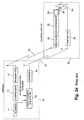
- the vehicle comprises a camera. Images captured by said camera are conveyed to a control center and presented on a display.
- the vehicle's control mechanism By guiding the vehicle, or marking a target point or area on a displayed image, and by conveying the information relating to said marking of the vehicle, the vehicle's control mechanism (referred herein as “ inner control loop” or “inner guidance sub-system”) directs the vehicle's steering system to move towards the target point.
- inner control loop or “inner guidance sub-system”
- the term "operator” refers herein to a human being or automatic means (i.e., a computerized system) that makes the decisions as to what point or area to guide the vehicle. Concerning manual operation, the pointing can be carried out by a device (such as computer mouse, joystick, touch screen, and so forth). Concerning automatic means, neither a display nor pointing device is required, since an automaton can manipulate data without the intermediation of a display or pointing means.
- the image signal is compressed in order to reduce the bandwidth required for transmission.
- frames captured by camera 11 are compressed by a compressor 12 (generally a software/hardware component) and transmitted via transmitter 13 to the control center 20.
- the transmission from the vehicle to the control center 20 is referred to herein as "Downlink".
- the transmission is received by a receiver 21, decompressed by decompressor 22 (generally a software/hardware component) and the frames are displayed on display 23.
- decompressor 22 generally a software/hardware component
- the operator 24 uses a pointing device 25 (such as a mouse) to mark on the screen 23 the target point to which the vehicle should be guided.
- the coordinates of the marked point are transmitted to the vehicle via transmitter 26 of the remote control center.
- the transmission from the control center to the vehicle is referred to herein as "Uplink".
- the receiver 14 receives the control commands transmitted from the control center 20 and feeds them to the inner guidance sub-system 15.
- the inner guidance sub-system 15 further comprises a tracker or a navigation system (or both) 151 and a steering system 152 which directs the vehicle towards a certain point.
- Compressing and decompressing of images is carried out in order to reduce the amount of the transferred data, and to suit the restrictions of a narrow-bandwidth communication channel.
- the outer loop consists of the following stages:
- the inner loop at the vehicle adjusts the steering system of the vehicle to move towards the target point.
- Certain factors may cause a lag between the time an image is captured by the camera and the time the same frame is presented on the display at the remote control-center.
- a major reason for this lag may be associated with the downlink bandwidth allocated for transferring the images. If the bandwidth is not wide enough, the use of compression techniques may be required. These techniques may involve skipping frames or using bi-directional estimation (referred to as B frames in the compression standards such as ISO 13818-2 (MPEG2-video). The lag between the captured frame and the displayed frame is inherent to both techniques. In general, video (or image) compression produces bits at a variable rate. Transferring these bits via a fixed bit-rate channel requires buffering (at both ends of the channel), and thus results in additional lagging.
- the lag may appear in the downlink route, as well as in the uplink.
- a partial solution to this problem, as presented in the prior art, is the expansion of the bandwidth. In this way, a higher rate of transferred data between a vehicle and a control center can be obtained.
- the drawback of this solution is the exhausting of bandwidth resources. Due to the bandwidth restrictions, different solutions are required.
- this solution when applied, reduces only the compression lag, but has no affect on other causes of the lag.
- EP 606,173 discloses a method and system for guiding a vehicle via a lagged communication channel, which comprises at the vehicle both a camera and a 3-D imager.
- the present invention relates to a method for guiding from a remote control center a vehicle towards a target object, said remote control center communicating with the vehicle by means of a lagged communication channel, the method comprises the steps of:
- each partial frame data represents an intermediate frame and each full frame data represents a reference frame.
- At least one intermediate frame is produced between any two reference frames.
- each partial frame data comprises a set of GMPs (Global Motion Parameters) indicating the global change of a given intermediate frame with respect to a previous reference frame, as calculated using a GMF (Global Motion Function).
- GMPs Global Motion Parameters
- GMF Global Motion Function
- reference frames are compressed at the vehicle before being sent to the control center, and decompressed at the control center.
- At least one set of GMPs is sent to the control center between any two compressed reference frames.
- a same GMF is used at the vehicle and at the control center.
- each reference frame is displayed after being decompressed at the control center.
- each intermediate frame is reconstructed and displayed at the control center, using the GMF and GMPs of same frame, as received, and data relating to a previous reference frame.
- the method further comprising backward activating a GMF to convert the marked coordinates to coordinates on a previous reference frame, before performing the fast forward tracing at the vehicle.
- the activation of the backward GMF is carried out at the vehicle.
- the activation of the backward GMF is carried out at the control center.
- the fast forward tracing of the object coordinates from the reference frame towards the most recently available captured frame is carried out by means of cascade activating a GMF at the vehicle, starting from the object coordinates on a reference frame and applying the function on all or some of newer saved frame GMPs until determining said target coordinates to target coordinates on the most recently captured frame.
- the fast forward tracing of the object coordinates from the reference frame towards the most recently available captured frame is carried out by means of activating a fast forward object tracing utility at the vehicle, starting from the target coordinates on a reference frame and applying the utility on all newer saved frames until determining the coordinates of the target on the most recently captured frame.
- the fast forward object tracing utility at the vehicle first identifies the marked object region on a reference frame by means of the coordinates as provided from the control center, and then uses means such as correlation for determining the region movement in all newer saved frames until determining the coordinates of the target, being within said region, on the most recently captured frame.
- the said inner guidance sub-system is a system capable of tracking an object to a point, to a certain direction, or a combination thereof by means of a navigation sub-system, a tracker sub-system or a combination thereof.
- the full frame data representing a reference frame comprises pixel representation data of the frame.
- the reference frame is reconstructed and displayed at the control center by using said pixel representation data.
- the full frame data further comprises at least one set of GMPs indicating the global change of the reference frame with respect to a previous reference frame.
- the reference frame is reconstructed and displayed at the control center by either using said pixel representation data or by substituting one of said set of GMPs indicating the global change of the reference frame with respect to a previous reference frame in a GMF.
- the camera provides a sequence of frames a portion of which eventually are presented to the operator to provide the information needed to guide the vehicle. While viewing these frames, the operator may mark a new target to which the remote vehicle should be guided.
- a sequence of images as "video sequence”, even if the rate of images is too low to encompass this term.
- a sequence of frames having about 40 milliseconds between each adjacent frame, produces a "live" image.
- US 5,835,147 describes a video signal comprising a sequence of segments, each containing one "reference” frame (being the first frame of the segment) followed by one or more "intermediate” frames.
- a segment of video signal including a reference frame and mathematical expressions describing the change between any intermediate frame and a corresponding reference frame, is applied according to the present invention. It should be noted that the term "segment” when used herein refers to one reference frame, and zero or more consequent intermediate frames following said reference frame.
- the function G ⁇ [ G x , G y ], hereinafter referred to as the "global motion function" describes only the "global" change between a first frame and a consequent frame, and it assumes the change at all points within the frame satisfy a same function. The amount of data required to reconstruct said consequent frame from said given first frame, is minimal.
- GMF Global Motion Function
- the reference frames can be compressed by compression methods known in the art, and hence, further reduce the amount of data required for storing the video signal.
- GMF Global Motion Parameters
- GMC Global Motion Calculator
- a choice of the GMF type should be made a-priory, and a same choice should be known and applied both at the vehicle and at the control center site. If at any specific time one of sites determines to use a different GMF, it should transmit a signal to the other party informing it of the change, and allowing it to adapt itself to that change. Therefore, the following notation can be used:
- GMP(F1) denotes applying the GMF to F1 using the GMP (equivalent to GMF(F1,GMP) ⁇ F2).
- GMP -1 (F1) equivalent of GMF -1 (F2,GMP) ⁇ F1
- GMP2*GMP1(F1) equivalent of GMF(GMF(F1,GMP1),GMP2) ⁇ F3.
- GMF is referred to herein as one function that is applied to the whole frame.
- the frame may be divided to sub-images (or spatial segments) and a different GMF may be used for each sub-frame (or spatial segment).
- GMP in that case, when used, may refer to a set of several GMPs.
- FIG. 3 schematically illustrates a compressed video signal, according to the prior art.
- a segment comprises the update frame 51, and the global motion parameters 52 to 55.
- the intermediate frames are reconstructed using the reference frame 51 and the global motion parameters 52 to 55.
- the decompressor may produce an estimated GMP. For example, if the GMP of frame 53 is not transmitted, a proper estimation of it may be produced from the GMP of frames 52 and 54.
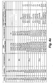
- Fig. 4a provides a typical case describing some of the cases and problems that the present invention solves.
- the columns are:
- a frame F1 which has been captured in time slice T1 is displayed on the control center display only in time slice T9. More particularly, in this example, the total lag is 8 frames, i.e., at the time stamp Fi was captured, the operator watches frame F(i-8). Later, in time slices T10, T11, T12, and T13, intermediate frames F2 to F5 respectively are displayed.
- the notation F1 refers to reconstructing the original frame F1 from a compressed frame.
- the number of skipped frames is constant (4 in this example).
- an 'adaptive' system is used.
- the number of skipped frames is not kept constant but is rather dynamically changed depending on occupancy of the buffers.
- the idea of controlling system parameters according to buffer occupancy is not new (see ISO14496-2).
- a simple embodiment of the adaptive embodiment of the present invention can set a threshold on the number of bits waiting to be transmitted in the output buffer at the vehicle site. Only when the number of bits in the buffer is lower than the threshold, the next frame is set to be a reference frame.
- the vehicle is equipped with a inner guidance sub-system that comprises an inner control loop for guiding the vehicle towards a marked target point.
- the target point may be static (for example, a fixed point in the scenery) or dynamic (for example, another moving vehicle). This section deals with the tracking of a static target point.
- An embodiment of the present invention dealing with the tracking of a dynamic target point follows.
- the vehicle Due to the lag of the communication in the downlink channel (i.e., from the vehicle to the control center), at the time the operator marks on a displayed frame an object to which the vehicle should be guided, the vehicle may not be present in this place anymore. Moreover, due to the uplink lag, when the control instruction to the vehicle which encapsulates this mark arrives back at the vehicle, the vehicle is most probably further away from the location of the vehicle when the mark has been set.
- two alternative embodiments can be used in order to overcome this obstacle, enabling the operator to guide the vehicle to a static object.
- the two embodiments differ by the location in which the "trace backward" step is performed. In the first embodiment this step is performed at the control center. In the second embodiment this step is performed at the vehicle.
- the tracing of a static target point from the frame on which it was marked to the current frame is a matter of applying a cascade of GMFs operations using the stored GMPs.
- object tracing utility refers herein to a utility (software and/or hardware) that can detect where a predefined object (e.g., an object marked on a previous frame of the same video sequence) appears on a frame.
- a predefined object e.g., an object marked on a previous frame of the same video sequence
- tracing an object on a frame sequence is a well-known subject in the art, and hence this subject is not discussed further herein.
- Sophisticated trackers can cope with a complicated situation such as maneuvering of the tracked object as well as maneuvering of the tracking vehicle itself.
- a typical object tracking utility may use a criterion of maximum correlation to track an object between two frames.
- Some other known techniques are edge detection, change detection, feature extraction and tracking, fuzzy logic, and more, or a combination thereof.
- the vehicle has an object tracking utility of some sort, which is a part of the inner loop so that once the operator marks an object to be tracked, the vehicle autonomously tracks the object. Still, it is usually the task of the operator to see that the tracking is maintained and to update or change the tracking point when needed (e.g. if the vehicle approaches the tracked object, new details may become apparent).
- the operator uses the outer loop, which as said is a lagged loop.
- Marking a dynamic target-point suffers from the same problems as described above in the section "Marking a static target-point" and, on top of it, it suffers from problems stemming from the fact that the object to be tracked is moving.
- the operator marks a point on the displayed frame, not only that the tracking vehicle is not at the point in which it was when the frame was taken, but also the tracked object has most probably moved in an unpredictable, manner.
- the control instruction to the vehicle arrives back to the vehicle, both the vehicle and the object to be tracked may be even further away.
- Fig. 5a schematically illustrates a sequence of video frames photographed by a camera mounted on a vehicle.
- Fig. 5b schematically illustrates the video frames of Fig. 5a, as presented on the operator's display, according to one embodiment of the invention.
- Fig. 5b the reference frames are emphasized, as may be seen in frames 101, 105, and 109, and the intermediate frames are not emphasized.
- the object 60 moves from the left upper corner downwards as is reflected in the capture frames of Fig. 5a.
- the position of the object 60 along a segment i.e., within the reference frame and the following intermediate frames is constant, as is shown in Fig. 5b.
- the correct location of a moving object is reflected only within reference frames.
- the intermediate frames reflect only a global change with respect to a previous reference frame, evolving from the moving of the vehicle.
- Objects within intermediate frames are displaced by a same distance with respect to their location within the previous reference frame. Therefore, this same amount of displacement is proper for all static objects within the scene.
- a moving object as is object 60
- the real location of the object is not reflected in the intermediate frames, but is correctly shown only within the reference frames 101, 105, 109, etc.
- the location of the moving object 60' is constant within the reference frames and the following intermediate frames (for example, within frames 101, 102, 103, and 104), and is updated only at the next reference frame (e.g., frame 105).
- a fast object-tracing utility is provided (at the vehicle) and the following steps are taken:
- the tracing of a dynamic target point from the frame on which it was marked to the current frame is done in two steps.
- the first step is identical to the corresponding step in the case of a static target point.
- the second step makes use of the fast object tracing utility to trace the object using frames stored in the memory. This issue will be clarified using the same example used for the static target point case, referring to figure 4a:
- the number of frames to be stored at the vehicle should be at least the number of lagged frames in the system.
- the number of stored frames may be reduced, e.g., by storing every other frame, if the tracing utility used is capable of tracing an object in a diluted sequence (typically compensating by enlarging the search area).
- the distinction between a 'fast', object-tracing utility of the outer loop and the 'regular' tracker of the inner loop is a matter of convenience: the two tracers may be just one tracer operating in two different modes.
- skipping frames i.e., these frames are not captured and processed at all
- the skipped frames are "filled in” by a motion compensated version of previous transmitted frames.
- an estimation of the GMP is used instead.
- an estimated GMP may be calculated either by extrapolating from previous transmitted GMPs or by interpolating from previous and subsequent transmitted GMPs (using delay). Extrapolation or interpolation may be carried out by methods well known in the literature, such as linear weighing or Kalman filtering. In the case of tracking a dynamic target-point the tracing utility should be able to trace objects in a diluted video sequence.
- the same GMF is used at the vehicle and at the control center.
- either the vehicle or the control center may wish to use some other GMF.
- the side that initiate the change should notify the other side (by means of the communications channel) which GMF to use and when (i.e. on which time stamp) the change should be effected.
- a set of GMFs may be stored in each side (i.e transitional, affine, perspective, etc.).
- One of the GMFs is set to be the default one i.e. the one that is used upon startup of the system. In that case, when one side wishes to change the GMF, it only has to send the index of the said GMF and the time stamp for effecting the change.
- the GMC may divide the image into several parts (spatial segments) and compute separate GMPs for each part (optionaly based on different GMFs). In that case it must convey all the relevant data for reconstruction and back-tracking to the control center, i.e. the segments boundaries, the GMF used at each segment and the resulting GMPs.
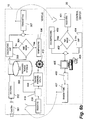
- Fig. 6a is a block diagram of a system for guiding a remote vehicle towards a static object via lagged communication channel, according to a preferred embodiment of the invention.
- Fig. 6b is a block diagram of a system for guiding a remote vehicle towards a dynamic object via a lagged communication channel, according to an embodiment of the invention.
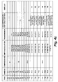
- Figs. 4b and 4c disclose two embodiments of the invention in which said drawbacks are resolved, at least to some extent.
- the object of the embodiment of Fig. 4b is to display at the control center frames that are most updated in their point of view, with a minimal lag, although they may include blank areas.
- the embodiment of Fig. 4b is advantageous with respect to the embodiment of Fig. 4a, in that the perspective is more updated. More particularly, for example, while in the embodiment of Fig. 4a the perspective of F 6 is displayed only when the reference frame F 6 is available for display, i.e., in time T14, in the embodiment of Fig. 4b, the perspective of F 6 is displayed in time T10. However, while in the embodiment of Fig. 4a all the reference frames, when displayed, are clear of blank areas, the frames of the embodiment of Fig. 4b may include blank areas, as all the frames which are displayed are frames on which a GMF is applied.
- the object of the embodiment of Fig. 4c is to display frames that contain minimum blank areas, although the delay in displaying them is considerable.
- each intermediate frame is a combination of two portions calculated by two separate GMF calculations. It should be noted that preferably one of the two portions is defined as a primary portion. The second portion is calculated only to fill black areas in the first.
- the primary portion is preferably the one for which the calculated frame portion is closer to a reference frame. More particularly, in the calculation of F 5, the portion resulting from G5(F1) is defined as the secondary portion, and the portion resulting from the calculation G5 * G6 -1 (F6) is defined as the primary portion, as the calculated frame F 5 is closer to the reference frame F 6 than to the reference frame F 1, and therefore this portion results in smaller blank areas (which are then filled by the secondary portion).
- channel lag Three types of lags are included under the term “channel lag”, as follows:
- the induced lag instability in the vehicle's control loop may be viewed as comprising two sub-problems:
- the frame size is not fixed but selectable by the operator. In very low bandwidth conditions, the operator may prefer to receive only a portion of the field of view of the camera, but at higher quality and/or higher refresh rate (that is, fewer skipped frames). This may be known as an ROI (Region of Interest) operation.
- ROI Region of Interest
- the number of frames of a segment affects the performance of a system for guiding a remote vehicle. For example, as mentioned above, only reference frames are real captured images, while the intermediate frames are actually transformations of the reference frames. Thus, an object that enters the camera's frame after the reference frame, and disappears before the next reference frame, cannot be seen by the operator.
- One of the options to decrease the probability of such a situation is to decrease the number of frames of a segment. However, this solution will cause additional lag, since more data must be transmitted.
Landscapes
- Engineering & Computer Science (AREA)
- Radar, Positioning & Navigation (AREA)
- Remote Sensing (AREA)
- Physics & Mathematics (AREA)
- Aviation & Aerospace Engineering (AREA)
- General Physics & Mathematics (AREA)
- Automation & Control Theory (AREA)
- Multimedia (AREA)
- Computer Vision & Pattern Recognition (AREA)
- Electromagnetism (AREA)
- Traffic Control Systems (AREA)
- Closed-Circuit Television Systems (AREA)
- Image Analysis (AREA)
- Platform Screen Doors And Railroad Systems (AREA)
- Near-Field Transmission Systems (AREA)
- Image Processing (AREA)
- Transceivers (AREA)
- Control Of Position, Course, Altitude, Or Attitude Of Moving Bodies (AREA)
Claims (25)
- Ein Verfahren zum Führen eines Fahrzeugs (10) von einer Kontrollstation zu einem Zielobjekt, wobei die Kontrollstation mit dem Fahrzeug mittels eines Übertragungskanals kommuniziert, mit den Verfahrensschritten:An dem Fahrzeug:I) Periodisches Einfangen von Bildern mittels einer Kamera (101,301), Zuordnen eines zugehörigen, einzigartigen Zeitstempels zu jedem der eingefangenen Bilder, und Speichern von Vollbilddaten oder Teilbilddaten eingefangener Bilder und deren zugehöriger Zeitstempel in einem Speicher (103, 303) im Fahrzeug;II) Senden der Vollbilddaten, Teilbilddaten oder einer Kombination davon mit den entsprechend zugehörigen Zeitstempeln für jedes versendete Bild an die Kontrollstation (20) für eine Vielzahl von gespeicherten Bildern, um eine ungefähre oder exakte Version der gesendeten Bilder an der Kontrollstation zu rekonstruieren und anzuzeigen.An der Kontrollstation:III) Empfangen (201, 401) der Bilddaten und der zugehörigen Zeitstempel, sequentielles Rekonstruieren der Bilder aus den gesendeten Voll- und/oder Teilbilddaten, und Anzeigen der rekonstruierten Bilder auf einem Bildschirm;IV) Kennzeichnen eines Punktes auf einem spezifisch angezeigten Bild durch einen Benutzer an der Kontrollstation (20), Senden von Koordinatenangaben des gekennzeichneten Punktes, die auf dem spezifischen Bild oder auf einem in der Kontrollstation erhältlichen Referenzbild erscheinen, und dem zum spezifischen Bild oder Referenzbild zugehörigen Zeitstempel an das Fahrzeug;An dem Fahrzeug:V) Empfangen (208, 408) der gesendeten Koordinatenangaben und Bildzeitstempel;VI) Lokalisieren der Punkt- oder Objektkoordinaten auf einem vorher gespeicherten, entsprechenden Bild mit gleichem Zeitstempel unter Verwendung eines Bildverarbeitungsverfahrens und Verfolgen (209, 409) der Punkt- oder Objektkoordinaten des Bildes in den zuletzt erhältlichen, eingefangenen Bildern bei einer Rate, die größer ist als die der periodischen Bilderfassung, und Auffinden der Koordinaten des gleichen Punktes oder Objektes, wie in dem zuletzt erhältlichen, eingefangenen Bild erscheinend; undVII) Bereitstellen der Koordinaten des Zielpunktes oder Zielobjektes innerhalb des zuletzt erhältlichen, eingefangenen Bildes für ein inneres Führungsteilsystem (210, 410) des Fahrzeugs (10) zur Verfolgung des Objektes.
- Verfahren nach Anspruch 1, dadurch gekennzeichnet, dass die partiellen Bilddaten ein Zwischenbild und die Vollbilddaten ein Referenzbild darstellen.
- Verfahren nach Anspruch 2, dadurch gekennzeichnet, dass mindestens ein Zwischenbild zwischen zwei Referenzbildern erzeugt wird.
- Verfahren nach Anspruch 2, dadurch gekennzeichnet, dass die partiellen Bilddaten einen Satz globaler Bewegungsparameter aufweisen, welche die umfassende Änderung eines gegebenen Bildes in Bezug auf ein vorhergehendes Referenzbild anzeigen, wie unter der Verwendung einer globalen Bewegungsfunktion berechnet.
- Verfahren nach Anspruch 2, dadurch gekennzeichnet, dass die Referenzbilder vor der Versendung an die Kontrollstation am Fahrzeug komprimiert und an der Kontrollstation dekomprimiert werden.
- Verfahren nach Anspruch 5, dadurch gekennzeichnet, dass zumindest ein Satz globaler Bewegungsparameter zwischen zwei komprimierten Referenzbildern an die Kontrollstation gesendet wird.
- Verfahren nach Anspruch 4, dadurch gekennzeichnet, dass im Fahrzeug und in der Kontrollstation die gleiche globale Bewegungsfunktion verwendet wird.
- Verfahren nach Anspruch 7, dadurch gekennzeichnet, dass jedes Referenzbild nach der Dekomprimierung in der Kontrollstation angezeigt wird.
- Verfahren nach Anspruch 7, dadurch gekennzeichnet, dass jedes Zwischenbild in der Kontrollstation nach Aktivierung einer globalen Bewegungsfunktion unter Verwendung der globalen Bewegungsparameter des gleichen empfangenen Bildes und der Daten betreffend ein vorangegangenes Referenzbild angezeigt wird.
- Verfahren nach Anspruch 9, dadurch gekennzeichnet, dass das Verfahren ferner eine Rückwärtsaktivierung einer globalen Bewegungsfunktion aufweist, um die gekennzeichneten Koordinaten vor der Ausführung der Verfolgung am Fahrzeug in Koordinaten eines vorangegangenen Referenzbildes zu konvertieren.
- Verfahren nach Anspruch 10, dadurch gekennzeichnet, dass die rückwärtige Aktivierung der globalen Bewegungsfunktion im Fahrzeug ausgeführt wird.
- Verfahren nach Anspruch 10, dadurch gekennzeichnet, dass die rückwärtige Aktivierung der globalen Bewegungsfunktion in der Kontrollstation ausgeführt wird.
- Verfahren nach Anspruch 4 zum Führen des Fahrzeugs an ein statisches Ziel, wobei nur globale Bewegungsparameter von Zwischenbildern im Fahrzeug gespeichert werden.
- Verfahren nach Anspruch 10, dadurch gekennzeichnet, dass die Verfolgung der Objektkoordinaten vom Referenzbild bis zum zuletzt erhältlichen, eingefangenen Bild mittels einer die globale Bewegungsfunktion aktivierenden Kaskade im Fahrzeug ausgeführt wird, ausgehend von den Objektkoordinaten auf einem Referenzbild unter Anwendung der Funktion auf alle neueren, gespeicherten globalen Bildbewegungsparameter bis zur Bestimmung der Zielkoordinaten zu Zielkoordinaten auf dem zuletzt eingefangenen Bild.
- Verfahren nach Anspruch 4 zum Führen des Fahrzeugs an ein dynamisches Ziel, wobei die Vollbilddaten im Fahrzeug gespeichert werden.
- Verfahren nach Anspruch 15, dadurch gekennzeichnet, dass die Verfolgung der Objektkoordinaten vom Referenzbild bis zum zuletzt erhältlichen, eingefangenen Bild mittels der Aktivierung einer Objektverfolgungseinrichtung am Fahrzeug bei einer Rate, die größer ist als die der periodischen Bilderfassung ausgeführt wird, ausgehend von den Zielkoordinaten auf einem Referenzbild unter Anwendung der Einrichtung auf alle neueren, gespeicherten Bilder bis zur Bestimmung der Koordinaten des Ziels auf dem zuletzt eingefangenen Bild.
- Verfahren nach Anspruch 16, dadurch gekennzeichnet, dass die Objektverfolgungseinrichtung am Fahrzeug zunächst den markierten Objektbereich auf einem Referenzbild mittels der von der Kontrollstation bereitgestellten Koordinaten erkennt und dann die Korrelation zur Bestimmung des Bewegungsbereiches in all den neueren, gespeicherten Bildern bis zur Bestimmung der Koordinaten des Ziels verwendet, die innerhalb des Bereiches auf dem zuletzt eingefangenen Bild liegen.
- Verfahren nach Anspruch 1, dadurch gekennzeichnet, dass das innere Führungsteilsystem ein System ist, das imstande ist ein Objekt bis zu einem Punkt, in einer bestimmten Richtung oder einer Kombination davon mittels eines Navigationsteilsystems, einem Aufspürteilsystem oder einer Kombination davon aufzuspüren.
- Verfahren nach Anspruch 1, dadurch gekennzeichnet, dass die Vollbilddaten ein Referenzbild darstellen, wobei die Vollbilddaten Pixel Repräsentationsdaten des Bildes aufweisen.
- Verfahren nach Anspruch 19, dadurch gekennzeichnet, dass die Vollbilddaten ferner mindestens einen Satz globaler Bewegungsparameter aufweisen, welche die umfassende Änderung des Referenzbildes in Bezug auf ein vorhergehendes Referenzbild anzeigen.
- Verfahren nach Anspruch 19, dadurch gekennzeichnet, dass das Referenzbild in der Kontrollstation unter Verwendung der Pixel Repräsentationsdaten rekonstruiert und angezeigt wird.
- Verfahren nach Anspruch 20, dadurch gekennzeichnet, dass das Referenzbild in der Kontrollstation unter Verwendung entweder der Pixel Repräsentationsdaten oder durch Substitution eines der Parameter aus dem Satz von globalen Bewegungsparametern, welche die umfassende Änderung des Referenzbildes in Bezug auf ein vorhergehendes Referenzbild in einer globalen Bewegungsfunktion anzeigen, rekonstruiert und angezeigt wird.
- Verfahren nach Anspruch 1, dadurch gekennzeichnet, dass der Benutzer ein computerunterstütztes System anstelle eines menschlichen Benutzers ist.
- Verfahren nach Anspruch 1, dadurch gekennzeichnet, dass die globalen Bewegungsparameter zur Erstellung von Bildern verwendet werden, sobald diese in der Kontrollstation ankommen, um Bilder mit einer minimalen Verzögerung zu erzeugen.
- Verfahren nach Anspruch 1, dadurch gekennzeichnet, dass eine Rekonstruktion eines Bildes auf mehr als einem Referenzbild basiert.
Applications Claiming Priority (3)
| Application Number | Priority Date | Filing Date | Title |
|---|---|---|---|
| IL147370A IL147370A (en) | 2001-12-27 | 2001-12-27 | Method and system for guiding a remote vehicle via lagged communication channel |
| IL14737001 | 2001-12-27 | ||
| PCT/IL2002/001030 WO2003060416A1 (en) | 2001-12-27 | 2002-12-23 | Method and system for guiding a remote vehicle via lagged communication channel |
Publications (3)
| Publication Number | Publication Date |
|---|---|
| EP1468241A1 EP1468241A1 (de) | 2004-10-20 |
| EP1468241B1 true EP1468241B1 (de) | 2007-01-17 |
| EP1468241B2 EP1468241B2 (de) | 2011-03-23 |
Family
ID=11075912
Family Applications (1)
| Application Number | Title | Priority Date | Filing Date |
|---|---|---|---|
| EP02806378A Expired - Lifetime EP1468241B2 (de) | 2001-12-27 | 2002-12-23 | Verfahren und system zum führen eines fernfahrzeugs über einen zeitverzögerten kommunikationskanal |
Country Status (12)
| Country | Link |
|---|---|
| US (1) | US7620483B2 (de) |
| EP (1) | EP1468241B2 (de) |
| KR (1) | KR20040081444A (de) |
| AT (1) | ATE352021T1 (de) |
| AU (1) | AU2002366984B2 (de) |
| BR (1) | BRPI0215363B1 (de) |
| CA (1) | CA2471569C (de) |
| DE (1) | DE60217719T2 (de) |
| ES (1) | ES2280628T3 (de) |
| IL (1) | IL147370A (de) |
| PL (1) | PL205063B1 (de) |
| WO (1) | WO2003060416A1 (de) |
Families Citing this family (38)
| Publication number | Priority date | Publication date | Assignee | Title |
|---|---|---|---|---|
| IL147370A (en) † | 2001-12-27 | 2007-07-24 | Itzhak Florentin | Method and system for guiding a remote vehicle via lagged communication channel |
| PL1913557T3 (pl) | 2005-06-23 | 2016-12-30 | System i metoda śledzenia poruszających się obiektów | |
| US8120675B2 (en) * | 2006-10-17 | 2012-02-21 | Panasonic Corporation | Moving image recording/playback device |
| US8139108B2 (en) * | 2007-01-31 | 2012-03-20 | Caterpillar Inc. | Simulation system implementing real-time machine data |
| DE102008046215A1 (de) | 2008-09-08 | 2009-09-17 | Daimler Ag | Verfahren zur Ankoppelung eines Fahrzeugs an eine Ladestation |
| US20100259614A1 (en) * | 2009-04-14 | 2010-10-14 | Honeywell International Inc. | Delay Compensated Feature Target System |
| KR20130018795A (ko) * | 2010-03-26 | 2013-02-25 | 지멘스 에스에이에스 | 피안내 차량의 이동과 관련한 특정 이벤트를 관리하기 위한 방법 및 시스템 |
| DE102011107630A1 (de) * | 2011-06-30 | 2013-01-03 | Lfk-Lenkflugkörpersysteme Gmbh | Lenken eines Vehikels in Richtung eines Ziels |
| US8217945B1 (en) * | 2011-09-02 | 2012-07-10 | Metric Insights, Inc. | Social annotation of a single evolving visual representation of a changing dataset |
| FR2988507B1 (fr) * | 2012-03-23 | 2014-04-25 | Inst Francais Des Sciences Et Technologies Des Transports De Lamenagement Et Des Reseaux | Systeme d'assistance pour vehicule routier |
| IL219639A (en) | 2012-05-08 | 2016-04-21 | Israel Aerospace Ind Ltd | Remote object tracking |
| WO2014111923A1 (en) * | 2013-01-15 | 2014-07-24 | Israel Aerospace Industries Ltd | Remote tracking of objects |
| IL224273B (en) | 2013-01-17 | 2018-05-31 | Cohen Yossi | Delay compensation during remote sensor control |
| WO2014141479A1 (ja) * | 2013-03-15 | 2014-09-18 | 株式会社日立製作所 | 遠隔操作システム |
| US11408699B2 (en) | 2014-03-21 | 2022-08-09 | Armaments Research Company Inc. | Firearm usage monitoring system |
| US10999012B2 (en) * | 2014-11-07 | 2021-05-04 | Strong Force Iot Portfolio 2016, Llc | Packet coding based network communication |
| DE102016207240A1 (de) * | 2016-04-28 | 2017-11-02 | Robert Bosch Gmbh | Fahrzeugleitsystem für ein Fahrzeug, Fahrzeug |
| JP6720415B2 (ja) * | 2016-12-06 | 2020-07-08 | ニッサン ノース アメリカ,インク | 自律走行車のための帯域幅制約画像処理 |
| US11295542B2 (en) | 2018-10-12 | 2022-04-05 | Armaments Research Company, Inc. | Remote support system and methods for firearm and asset monitoring including coalescing cones of fire |
| US12624914B2 (en) | 2017-01-27 | 2026-05-12 | Armaments Research Company, Inc. | Weapon usage monitoring system having predictive maintenance and performance metrics |
| US11125521B2 (en) | 2017-01-27 | 2021-09-21 | Armaments Research Company, Inc. | Weapon usage monitoring system for initiating notifications and commands based on dashboard actions |
| US11215416B2 (en) | 2017-01-27 | 2022-01-04 | Armaments Research Company, Inc. | Weapon monitoring system with a map-based dashboard interface |
| US12487044B2 (en) | 2017-01-27 | 2025-12-02 | Armaments Research Company, Inc. | Weapon usage monitoring system having discharge event monitoring directed toward quick change barrel |
| US11635269B2 (en) | 2017-01-27 | 2023-04-25 | Araments Research Company Inc. | Weapon usage monitoring system with virtual reality system for deployment location event analysis |
| US12018902B2 (en) | 2017-01-27 | 2024-06-25 | Armaments Research Company Inc. | Weapon usage monitoring system having shot correlation monitoring based on user fatigue |
| CN107589745B (zh) * | 2017-09-22 | 2021-04-16 | 京东方科技集团股份有限公司 | 驾驶方法、车载驾驶端、远程驾驶端、设备和存储介质 |
| WO2020112134A1 (en) * | 2018-11-30 | 2020-06-04 | Danfoss Power Solutions, Inc. | Method and system for remote machine control |
| US12298772B2 (en) * | 2018-12-19 | 2025-05-13 | Zoox, Inc. | Transition to safe state based on age/integrity of critical messages |
| US11281214B2 (en) | 2018-12-19 | 2022-03-22 | Zoox, Inc. | Safe system operation using CPU usage information |
| US11099573B2 (en) | 2018-12-19 | 2021-08-24 | Zoox, Inc. | Safe system operation using latency determinations |
| EP3690852B1 (de) * | 2019-01-29 | 2024-12-11 | Volkswagen Aktiengesellschaft | System, fahrzeug, netzwerkkomponente, vorrichtungen, verfahren und computerprogramme für ein fahrzeug und eine netzwerkkomponente |
| CN110262565B (zh) * | 2019-05-28 | 2023-03-21 | 深圳市吉影科技有限公司 | 应用于水下六推无人机的目标跟踪运动控制方法及装置 |
| EP3772226B1 (de) * | 2019-07-30 | 2023-01-25 | Volkswagen AG | Verfahren, computerprogramme und vorrichtungen für ein befehlszentrum und fahrzeug |
| DE102019132759A1 (de) | 2019-12-03 | 2021-06-10 | Valeo Schalter Und Sensoren Gmbh | Verfahren zum ferngesteuerten Führen eines Kraftfahrzeugs mit einem Teleoperator,Computerprogrammprodukt und Teleoperationsführungssystem |
| EP3910937B1 (de) | 2020-05-11 | 2024-03-27 | Voysys AB | Verfahren und system zur überwachung der kommunikation zwischen fahrzeug und fernbetreiber |
| US11991346B2 (en) | 2021-11-15 | 2024-05-21 | Ford Global Technologies, Llc | Video streaming anomaly detection |
| JP7759247B2 (ja) * | 2021-12-07 | 2025-10-23 | 株式会社Subaru | 車両走行の遠隔制御システム |
| JP7524915B2 (ja) * | 2022-02-14 | 2024-07-30 | トヨタ自動車株式会社 | 制御装置、制御方法、及び制御プログラム |
Family Cites Families (20)
| Publication number | Priority date | Publication date | Assignee | Title |
|---|---|---|---|---|
| US606105A (en) * | 1898-06-21 | Draw-bar for railway-cars | ||
| GB1568058A (en) * | 1975-11-21 | 1980-05-21 | Emi Ltd | Tracking and/or huidance systems |
| JPS62155140A (ja) * | 1985-12-27 | 1987-07-10 | Aisin Warner Ltd | 車両制御用道路画像入力方式 |
| US4720871A (en) * | 1986-06-13 | 1988-01-19 | Hughes Aircraft Company | Digital image convolution processor method and apparatus |
| US4855822A (en) * | 1988-01-26 | 1989-08-08 | Honeywell, Inc. | Human engineered remote driving system |
| US5062056A (en) | 1989-10-18 | 1991-10-29 | Hughes Aircraft Company | Apparatus and method for tracking a target |
| US5956250A (en) * | 1990-02-05 | 1999-09-21 | Caterpillar Inc. | Apparatus and method for autonomous vehicle navigation using absolute data |
| US5155683A (en) * | 1991-04-11 | 1992-10-13 | Wadiatur Rahim | Vehicle remote guidance with path control |
| FR2700213B1 (fr) * | 1993-01-05 | 1995-03-24 | Sfim | Ensemble de guidage. |
| US5596319A (en) † | 1994-10-31 | 1997-01-21 | Spry; Willie L. | Vehicle remote control system |
| US5717463A (en) * | 1995-07-24 | 1998-02-10 | Motorola, Inc. | Method and system for estimating motion within a video sequence |
| IL116060A (en) * | 1995-11-19 | 2000-02-17 | Israel State | Method for compression and decompression of a video signal |
| US5907626A (en) * | 1996-08-02 | 1999-05-25 | Eastman Kodak Company | Method for object tracking and mosaicing in an image sequence using a two-dimensional mesh |
| US6061055A (en) | 1997-03-21 | 2000-05-09 | Autodesk, Inc. | Method of tracking objects with an imaging device |
| AU2317200A (en) † | 1999-02-03 | 2000-08-25 | Elbit Systems Ltd | Delayed video tracking |
| US6545743B1 (en) * | 2000-05-22 | 2003-04-08 | Eastman Kodak Company | Producing an image of a portion of a photographic image onto a receiver using a digital image of the photographic image |
| US6654507B2 (en) * | 2000-12-14 | 2003-11-25 | Eastman Kodak Company | Automatically producing an image of a portion of a photographic image |
| CN101448162B (zh) * | 2001-12-17 | 2013-01-02 | 微软公司 | 处理视频图像的方法 |
| IL147370A (en) † | 2001-12-27 | 2007-07-24 | Itzhak Florentin | Method and system for guiding a remote vehicle via lagged communication channel |
| US7242713B2 (en) * | 2002-05-02 | 2007-07-10 | Microsoft Corporation | 2-D transforms for image and video coding |
-
2001
- 2001-12-27 IL IL147370A patent/IL147370A/en active IP Right Grant
-
2002
- 2002-12-23 BR BRPI0215363A patent/BRPI0215363B1/pt not_active IP Right Cessation
- 2002-12-23 PL PL369975A patent/PL205063B1/pl unknown
- 2002-12-23 AT AT02806378T patent/ATE352021T1/de not_active IP Right Cessation
- 2002-12-23 ES ES02806378T patent/ES2280628T3/es not_active Expired - Lifetime
- 2002-12-23 DE DE60217719T patent/DE60217719T2/de not_active Expired - Lifetime
- 2002-12-23 EP EP02806378A patent/EP1468241B2/de not_active Expired - Lifetime
- 2002-12-23 KR KR10-2004-7010214A patent/KR20040081444A/ko not_active Withdrawn
- 2002-12-23 US US10/499,799 patent/US7620483B2/en not_active Expired - Lifetime
- 2002-12-23 AU AU2002366984A patent/AU2002366984B2/en not_active Expired
- 2002-12-23 WO PCT/IL2002/001030 patent/WO2003060416A1/en not_active Ceased
- 2002-12-23 CA CA002471569A patent/CA2471569C/en not_active Expired - Lifetime
Also Published As
| Publication number | Publication date |
|---|---|
| PL205063B1 (pl) | 2010-03-31 |
| CA2471569A1 (en) | 2003-07-24 |
| US7620483B2 (en) | 2009-11-17 |
| AU2002366984A1 (en) | 2003-07-30 |
| CA2471569C (en) | 2009-11-24 |
| KR20040081444A (ko) | 2004-09-21 |
| PL369975A1 (en) | 2005-05-02 |
| US20050119801A1 (en) | 2005-06-02 |
| IL147370A (en) | 2007-07-24 |
| WO2003060416A1 (en) | 2003-07-24 |
| DE60217719T2 (de) | 2007-10-31 |
| EP1468241A1 (de) | 2004-10-20 |
| IL147370A0 (en) | 2002-12-01 |
| ATE352021T1 (de) | 2007-02-15 |
| BR0215363A (pt) | 2004-12-14 |
| DE60217719D1 (de) | 2007-03-08 |
| AU2002366984B2 (en) | 2008-08-28 |
| BRPI0215363B1 (pt) | 2016-08-30 |
| ES2280628T3 (es) | 2007-09-16 |
| EP1468241B2 (de) | 2011-03-23 |
Similar Documents
| Publication | Publication Date | Title |
|---|---|---|
| EP1468241B2 (de) | Verfahren und system zum führen eines fernfahrzeugs über einen zeitverzögerten kommunikationskanal | |
| US20180265197A1 (en) | First-Person Viewer for Unmanned Vehicles | |
| US11949982B2 (en) | Method of forming a processed video stream | |
| CA2261936A1 (en) | Embedded mission avionics data link system | |
| US11606481B2 (en) | Reducing judder using motion vectors | |
| CN102124491B (zh) | 在移动站远程控制装载的摄像机的方法及设备 | |
| US6956902B2 (en) | Method and apparatus for a multi-user video navigation system | |
| US20170118468A1 (en) | Image receiving device, image transmission system, and image receiving method | |
| JP2019001203A (ja) | 鉄道運転支援システム | |
| US11216662B2 (en) | Efficient transmission of video over low bandwidth channels | |
| US20240310841A1 (en) | Remote Vehicle Operation with High Latency Communications | |
| US10200574B2 (en) | Method and system for generating a video frame | |
| EP1889442A1 (de) | Verfahren und system zum anzeigen eines interaktiven spielfilms über ein netzwerk | |
| US6701017B1 (en) | High resolution high-value added video transfer method system and storage medium by using pseudo natural image | |
| JP5188051B2 (ja) | 表示制御装置及び表示装置 | |
| US6898240B2 (en) | Predictive edge extension into uncovered regions | |
| JPH0564172A (ja) | 映像通信方式および映像送信装置および映像受信装置 | |
| JP2001044941A (ja) | 移動無線通信装置 | |
| GB2528246A (en) | Region based image compression on a moving platform | |
| CN113791639A (zh) | 光电吊舱数据对齐方法、无人机及可读存储介质 | |
| KR20260045973A (ko) | 주행용 객체를 제어하기 위한 칵핏으로 영상을 안정적으로 송신하기 위한 방법 및 이를 이용한 컴퓨팅 장치 | |
| JPH1032831A (ja) | 中間画像生成装置 | |
| CN121442050A (zh) | 相机同步方法、设备、存储介质及计算机程序产品 | |
| JPH07274146A (ja) | 画像情報伝送方法及びシステム並びにこれらに適する送信方法、受信方法、送信局及び受信局 |
Legal Events
| Date | Code | Title | Description |
|---|---|---|---|
| PUAI | Public reference made under article 153(3) epc to a published international application that has entered the european phase |
Free format text: ORIGINAL CODE: 0009012 |
|
| 17P | Request for examination filed |
Effective date: 20040723 |
|
| AK | Designated contracting states |
Kind code of ref document: A1 Designated state(s): AT BE BG CH CY CZ DE DK EE ES FI FR GB GR IE IT LI LU MC NL PT SE SI SK TR |
|
| AX | Request for extension of the european patent |
Extension state: AL LT LV MK RO |
|
| GRAP | Despatch of communication of intention to grant a patent |
Free format text: ORIGINAL CODE: EPIDOSNIGR1 |
|
| GRAS | Grant fee paid |
Free format text: ORIGINAL CODE: EPIDOSNIGR3 |
|
| GRAA | (expected) grant |
Free format text: ORIGINAL CODE: 0009210 |
|
| AK | Designated contracting states |
Kind code of ref document: B1 Designated state(s): AT BE BG CH CY CZ DE DK EE ES FI FR GB GR IE IT LI LU MC NL PT SE SI SK TR |
|
| PG25 | Lapsed in a contracting state [announced via postgrant information from national office to epo] |
Ref country code: LI Free format text: LAPSE BECAUSE OF FAILURE TO SUBMIT A TRANSLATION OF THE DESCRIPTION OR TO PAY THE FEE WITHIN THE PRESCRIBED TIME-LIMIT Effective date: 20070117 Ref country code: DK Free format text: LAPSE BECAUSE OF FAILURE TO SUBMIT A TRANSLATION OF THE DESCRIPTION OR TO PAY THE FEE WITHIN THE PRESCRIBED TIME-LIMIT Effective date: 20070117 Ref country code: CH Free format text: LAPSE BECAUSE OF FAILURE TO SUBMIT A TRANSLATION OF THE DESCRIPTION OR TO PAY THE FEE WITHIN THE PRESCRIBED TIME-LIMIT Effective date: 20070117 Ref country code: AT Free format text: LAPSE BECAUSE OF FAILURE TO SUBMIT A TRANSLATION OF THE DESCRIPTION OR TO PAY THE FEE WITHIN THE PRESCRIBED TIME-LIMIT Effective date: 20070117 Ref country code: SI Free format text: LAPSE BECAUSE OF FAILURE TO SUBMIT A TRANSLATION OF THE DESCRIPTION OR TO PAY THE FEE WITHIN THE PRESCRIBED TIME-LIMIT Effective date: 20070117 |
|
| REG | Reference to a national code |
Ref country code: GB Ref legal event code: FG4D |
|
| REG | Reference to a national code |
Ref country code: CH Ref legal event code: EP |
|
| REG | Reference to a national code |
Ref country code: IE Ref legal event code: FG4D |
|
| REF | Corresponds to: |
Ref document number: 60217719 Country of ref document: DE Date of ref document: 20070308 Kind code of ref document: P |
|
| PG25 | Lapsed in a contracting state [announced via postgrant information from national office to epo] |
Ref country code: BG Free format text: LAPSE BECAUSE OF THE APPLICANT RENOUNCES Effective date: 20070418 |
|
| REG | Reference to a national code |
Ref country code: SE Ref legal event code: TRGR |
|
| REG | Reference to a national code |
Ref country code: GR Ref legal event code: EP Ref document number: 20070401223 Country of ref document: GR |
|
| PG25 | Lapsed in a contracting state [announced via postgrant information from national office to epo] |
Ref country code: PT Free format text: LAPSE BECAUSE OF FAILURE TO SUBMIT A TRANSLATION OF THE DESCRIPTION OR TO PAY THE FEE WITHIN THE PRESCRIBED TIME-LIMIT Effective date: 20070618 |
|
| REG | Reference to a national code |
Ref country code: CH Ref legal event code: PL |
|
| ET | Fr: translation filed | ||
| REG | Reference to a national code |
Ref country code: ES Ref legal event code: FG2A Ref document number: 2280628 Country of ref document: ES Kind code of ref document: T3 |
|
| PLBI | Opposition filed |
Free format text: ORIGINAL CODE: 0009260 |
|
| PLAX | Notice of opposition and request to file observation + time limit sent |
Free format text: ORIGINAL CODE: EPIDOSNOBS2 |
|
| 26 | Opposition filed |
Opponent name: ELBIT SYSTEMS LTD. Effective date: 20071015 |
|
| PG25 | Lapsed in a contracting state [announced via postgrant information from national office to epo] |
Ref country code: SK Free format text: LAPSE BECAUSE OF FAILURE TO SUBMIT A TRANSLATION OF THE DESCRIPTION OR TO PAY THE FEE WITHIN THE PRESCRIBED TIME-LIMIT Effective date: 20070117 |
|
| NLR1 | Nl: opposition has been filed with the epo |
Opponent name: ELBIT SYSTEMS LTD. |
|
| PG25 | Lapsed in a contracting state [announced via postgrant information from national office to epo] |
Ref country code: CZ Free format text: LAPSE BECAUSE OF FAILURE TO SUBMIT A TRANSLATION OF THE DESCRIPTION OR TO PAY THE FEE WITHIN THE PRESCRIBED TIME-LIMIT Effective date: 20070117 Ref country code: BE Free format text: LAPSE BECAUSE OF FAILURE TO SUBMIT A TRANSLATION OF THE DESCRIPTION OR TO PAY THE FEE WITHIN THE PRESCRIBED TIME-LIMIT Effective date: 20070117 |
|
| PLAF | Information modified related to communication of a notice of opposition and request to file observations + time limit |
Free format text: ORIGINAL CODE: EPIDOSCOBS2 |
|
| PLBB | Reply of patent proprietor to notice(s) of opposition received |
Free format text: ORIGINAL CODE: EPIDOSNOBS3 |
|
| PG25 | Lapsed in a contracting state [announced via postgrant information from national office to epo] |
Ref country code: MC Free format text: LAPSE BECAUSE OF NON-PAYMENT OF DUE FEES Effective date: 20071231 |
|
| GBPC | Gb: european patent ceased through non-payment of renewal fee |
Effective date: 20071223 |
|
| PG25 | Lapsed in a contracting state [announced via postgrant information from national office to epo] |
Ref country code: IE Free format text: LAPSE BECAUSE OF NON-PAYMENT OF DUE FEES Effective date: 20071224 |
|
| PG25 | Lapsed in a contracting state [announced via postgrant information from national office to epo] |
Ref country code: GB Free format text: LAPSE BECAUSE OF NON-PAYMENT OF DUE FEES Effective date: 20071223 |
|
| PG25 | Lapsed in a contracting state [announced via postgrant information from national office to epo] |
Ref country code: EE Free format text: LAPSE BECAUSE OF FAILURE TO SUBMIT A TRANSLATION OF THE DESCRIPTION OR TO PAY THE FEE WITHIN THE PRESCRIBED TIME-LIMIT Effective date: 20070117 |
|
| PG25 | Lapsed in a contracting state [announced via postgrant information from national office to epo] |
Ref country code: CY Free format text: LAPSE BECAUSE OF FAILURE TO SUBMIT A TRANSLATION OF THE DESCRIPTION OR TO PAY THE FEE WITHIN THE PRESCRIBED TIME-LIMIT Effective date: 20070117 |
|
| PG25 | Lapsed in a contracting state [announced via postgrant information from national office to epo] |
Ref country code: LU Free format text: LAPSE BECAUSE OF NON-PAYMENT OF DUE FEES Effective date: 20071223 |
|
| PLBP | Opposition withdrawn |
Free format text: ORIGINAL CODE: 0009264 |
|
| PUAH | Patent maintained in amended form |
Free format text: ORIGINAL CODE: 0009272 |
|
| STAA | Information on the status of an ep patent application or granted ep patent |
Free format text: STATUS: PATENT MAINTAINED AS AMENDED |
|
| PGFP | Annual fee paid to national office [announced via postgrant information from national office to epo] |
Ref country code: FI Payment date: 20101223 Year of fee payment: 9 |
|
| 27A | Patent maintained in amended form |
Effective date: 20110323 |
|
| AK | Designated contracting states |
Kind code of ref document: B2 Designated state(s): AT BE BG CH CY CZ DE DK EE ES FI FR GB GR IE IT LI LU MC NL PT SE SI SK TR |
|
| PG25 | Lapsed in a contracting state [announced via postgrant information from national office to epo] |
Ref country code: IT Free format text: LAPSE BECAUSE OF NON-PAYMENT OF DUE FEES Effective date: 20091223 |
|
| PGFP | Annual fee paid to national office [announced via postgrant information from national office to epo] |
Ref country code: TR Payment date: 20101222 Year of fee payment: 9 Ref country code: GR Payment date: 20101222 Year of fee payment: 9 |
|
| REG | Reference to a national code |
Ref country code: DE Ref legal event code: R102 Ref document number: 60217719 Country of ref document: DE Effective date: 20110323 |
|
| REG | Reference to a national code |
Ref country code: DE Ref legal event code: R135 Ref document number: 60217719 Country of ref document: DE |
|
| REG | Reference to a national code |
Ref country code: NL Ref legal event code: VDEP Effective date: 20110323 |
|
| PG25 | Lapsed in a contracting state [announced via postgrant information from national office to epo] |
Ref country code: GR Free format text: LAPSE BECAUSE OF FAILURE TO SUBMIT A TRANSLATION OF THE DESCRIPTION OR TO PAY THE FEE WITHIN THE PRESCRIBED TIME-LIMIT Effective date: 20110624 |
|
| PGFP | Annual fee paid to national office [announced via postgrant information from national office to epo] |
Ref country code: IT Payment date: 20101224 Year of fee payment: 9 |
|
| PGRI | Patent reinstated in contracting state [announced from national office to epo] |
Ref country code: IT Effective date: 20110616 |
|
| REG | Reference to a national code |
Ref country code: SE Ref legal event code: EUG |
|
| PG25 | Lapsed in a contracting state [announced via postgrant information from national office to epo] |
Ref country code: FI Free format text: LAPSE BECAUSE OF FAILURE TO SUBMIT A TRANSLATION OF THE DESCRIPTION OR TO PAY THE FEE WITHIN THE PRESCRIBED TIME-LIMIT Effective date: 20110322 |
|
| PG25 | Lapsed in a contracting state [announced via postgrant information from national office to epo] |
Ref country code: NL Free format text: LAPSE BECAUSE OF FAILURE TO SUBMIT A TRANSLATION OF THE DESCRIPTION OR TO PAY THE FEE WITHIN THE PRESCRIBED TIME-LIMIT Effective date: 20110323 |
|
| PGFP | Annual fee paid to national office [announced via postgrant information from national office to epo] |
Ref country code: SE Payment date: 20111228 Year of fee payment: 10 Ref country code: NL Payment date: 20111230 Year of fee payment: 10 |
|
| PGFP | Annual fee paid to national office [announced via postgrant information from national office to epo] |
Ref country code: FR Payment date: 20120201 Year of fee payment: 10 |
|
| PGFP | Annual fee paid to national office [announced via postgrant information from national office to epo] |
Ref country code: DE Payment date: 20111221 Year of fee payment: 10 |
|
| PG25 | Lapsed in a contracting state [announced via postgrant information from national office to epo] |
Ref country code: ES Free format text: LAPSE BECAUSE OF FAILURE TO SUBMIT A TRANSLATION OF THE DESCRIPTION OR TO PAY THE FEE WITHIN THE PRESCRIBED TIME-LIMIT Effective date: 20070428 |
|
| PG25 | Lapsed in a contracting state [announced via postgrant information from national office to epo] |
Ref country code: DE Free format text: LAPSE BECAUSE OF FAILURE TO SUBMIT A TRANSLATION OF THE DESCRIPTION OR TO PAY THE FEE WITHIN THE PRESCRIBED TIME-LIMIT Effective date: 20110624 |
|
| PGFP | Annual fee paid to national office [announced via postgrant information from national office to epo] |
Ref country code: ES Payment date: 20120104 Year of fee payment: 10 |
|
| PG25 | Lapsed in a contracting state [announced via postgrant information from national office to epo] |
Ref country code: ES Free format text: LAPSE BECAUSE OF FAILURE TO SUBMIT A TRANSLATION OF THE DESCRIPTION OR TO PAY THE FEE WITHIN THE PRESCRIBED TIME-LIMIT Effective date: 20110704 Ref country code: SE Free format text: LAPSE BECAUSE OF NON-PAYMENT OF DUE FEES Effective date: 20110721 |
|
| REG | Reference to a national code |
Ref country code: FR Ref legal event code: ST Effective date: 20130830 |
|
| PG25 | Lapsed in a contracting state [announced via postgrant information from national office to epo] |
Ref country code: FR Free format text: LAPSE BECAUSE OF NON-PAYMENT OF DUE FEES Effective date: 20130102 |
|
| PG25 | Lapsed in a contracting state [announced via postgrant information from national office to epo] |
Ref country code: IT Free format text: LAPSE BECAUSE OF NON-PAYMENT OF DUE FEES Effective date: 20121223 |
|
| PG25 | Lapsed in a contracting state [announced via postgrant information from national office to epo] |
Ref country code: TR Free format text: LAPSE BECAUSE OF NON-PAYMENT OF DUE FEES Effective date: 20121223 |