EP1468302B1 - Systeme de surveillance pour moteur electrique - Google Patents
Systeme de surveillance pour moteur electrique Download PDFInfo
- Publication number
- EP1468302B1 EP1468302B1 EP03700867A EP03700867A EP1468302B1 EP 1468302 B1 EP1468302 B1 EP 1468302B1 EP 03700867 A EP03700867 A EP 03700867A EP 03700867 A EP03700867 A EP 03700867A EP 1468302 B1 EP1468302 B1 EP 1468302B1
- Authority
- EP
- European Patent Office
- Prior art keywords
- electric motor
- antenna
- frequency
- diagnostic method
- monitoring system
- Prior art date
- Legal status (The legal status is an assumption and is not a legal conclusion. Google has not performed a legal analysis and makes no representation as to the accuracy of the status listed.)
- Expired - Lifetime
Links
- 238000012544 monitoring process Methods 0.000 title claims abstract description 54
- 238000012545 processing Methods 0.000 claims abstract description 23
- 238000005070 sampling Methods 0.000 claims abstract description 11
- 238000000034 method Methods 0.000 claims description 35
- 238000002405 diagnostic procedure Methods 0.000 claims description 20
- 238000001228 spectrum Methods 0.000 claims description 11
- 238000001514 detection method Methods 0.000 claims description 10
- 239000000523 sample Substances 0.000 claims description 10
- 239000004020 conductor Substances 0.000 claims description 8
- 230000003750 conditioning effect Effects 0.000 claims description 5
- 230000005684 electric field Effects 0.000 claims description 4
- 238000004458 analytical method Methods 0.000 claims description 3
- 238000012216 screening Methods 0.000 claims description 2
- 230000009466 transformation Effects 0.000 claims description 2
- 238000000844 transformation Methods 0.000 claims description 2
- 230000001629 suppression Effects 0.000 abstract description 3
- 238000013461 design Methods 0.000 abstract description 2
- 238000005259 measurement Methods 0.000 description 14
- 230000008901 benefit Effects 0.000 description 6
- 239000000463 material Substances 0.000 description 5
- 230000015572 biosynthetic process Effects 0.000 description 4
- 230000001965 increasing effect Effects 0.000 description 4
- 230000015556 catabolic process Effects 0.000 description 3
- 238000011109 contamination Methods 0.000 description 3
- 230000000694 effects Effects 0.000 description 3
- 238000009434 installation Methods 0.000 description 3
- 238000004519 manufacturing process Methods 0.000 description 3
- 238000000691 measurement method Methods 0.000 description 3
- 230000008569 process Effects 0.000 description 3
- 238000006731 degradation reaction Methods 0.000 description 2
- 239000012634 fragment Substances 0.000 description 2
- 238000013467 fragmentation Methods 0.000 description 2
- 238000006062 fragmentation reaction Methods 0.000 description 2
- 230000001939 inductive effect Effects 0.000 description 2
- 230000001788 irregular Effects 0.000 description 2
- 230000002035 prolonged effect Effects 0.000 description 2
- 238000012360 testing method Methods 0.000 description 2
- 238000004804 winding Methods 0.000 description 2
- 230000005355 Hall effect Effects 0.000 description 1
- 230000005856 abnormality Effects 0.000 description 1
- 230000001133 acceleration Effects 0.000 description 1
- 230000003466 anti-cipated effect Effects 0.000 description 1
- 239000003990 capacitor Substances 0.000 description 1
- 230000008859 change Effects 0.000 description 1
- 238000004891 communication Methods 0.000 description 1
- 230000001419 dependent effect Effects 0.000 description 1
- 230000006866 deterioration Effects 0.000 description 1
- 230000001627 detrimental effect Effects 0.000 description 1
- 238000006073 displacement reaction Methods 0.000 description 1
- 238000010891 electric arc Methods 0.000 description 1
- 238000009413 insulation Methods 0.000 description 1
- 238000002955 isolation Methods 0.000 description 1
- 238000012423 maintenance Methods 0.000 description 1
- 230000007246 mechanism Effects 0.000 description 1
- 238000012986 modification Methods 0.000 description 1
- 230000004048 modification Effects 0.000 description 1
- 238000012806 monitoring device Methods 0.000 description 1
- 230000003287 optical effect Effects 0.000 description 1
- 230000010355 oscillation Effects 0.000 description 1
- 230000008929 regeneration Effects 0.000 description 1
- 238000011069 regeneration method Methods 0.000 description 1
- 230000004044 response Effects 0.000 description 1
- 238000012546 transfer Methods 0.000 description 1
Images



Classifications
-
- G—PHYSICS
- G01—MEASURING; TESTING
- G01R—MEASURING ELECTRIC VARIABLES; MEASURING MAGNETIC VARIABLES
- G01R31/00—Arrangements for testing electric properties; Arrangements for locating electric faults; Arrangements for electrical testing characterised by what is being tested not provided for elsewhere
- G01R31/34—Testing dynamo-electric machines
- G01R31/343—Testing dynamo-electric machines in operation
-
- G—PHYSICS
- G01—MEASURING; TESTING
- G01R—MEASURING ELECTRIC VARIABLES; MEASURING MAGNETIC VARIABLES
- G01R31/00—Arrangements for testing electric properties; Arrangements for locating electric faults; Arrangements for electrical testing characterised by what is being tested not provided for elsewhere
- G01R31/12—Testing dielectric strength or breakdown voltage ; Testing or monitoring effectiveness or level of insulation, e.g. of a cable or of an apparatus, for example using partial discharge measurements; Electrostatic testing
- G01R31/1227—Testing dielectric strength or breakdown voltage ; Testing or monitoring effectiveness or level of insulation, e.g. of a cable or of an apparatus, for example using partial discharge measurements; Electrostatic testing of components, parts or materials
Definitions
- the present invention relates to the field of monitoring devices for electric motors.
- it relates to an arcing event detection device that provides a means for monitoring, recording and diagnosing a variety of electric motor operating and fault conditions.
- Figure 1 presents a simple two pole DC electric motor 1.
- the two pole DC electric motor 1 is shown in three different states of operation. From Figures 1(a), (b) and (c) it can be seen that the two pole DC electric motor 1 further comprises a motor field coil 2, two motor brushes 3, four armature coils 4 and a four sector commutator 5.
- Figure 1(d) and (e) show the conditions of the current in one of the armature coils 4 as the commutator 5 passes under a brush 3 from which a constant current I amps flows.
- the current flowing through the armature coil 4 prior to commutation is +I/2 amps (corresponding to Figure 1(a)).
- the current in the coil 4 is effectively reversed to -I/2 amps (corresponding to Figure 1(c)). This process of current reversal takes time T c seconds. If the current is fully reversed in time T c then there will be no arcing at the brush contact 3 and the current versus time profile shall be as shown in Figure 1(d).
- each of the factors outlined above affects the ability of an arc to form, the duration of the arc and the arc intensity.
- these arcing events are rather random in nature, the time duration typically varying between a few microseconds to several milliseconds.
- the arc is therefore essentially an impulse function with an associated broad band of frequencies in the range 0Hz to 1GHz.
- Tanisaka et al. exhibit certain inherent theoretical and practical problematic features. Most importantly the teachings are limited to the counting of the occurrence of sparking events.
- the described apparatus does not offer any facilities for relating an arcing event to a particular mechanical or electrical component within the electric motor. Similarly, there is no facility for physically locating the individual arcing events thus, information regarding the deterioration or alignment faults of the component parts of the electric motor cannot be extracted.
- Tanisaka et al A third major drawback of the teachings of Tanisaka et al is the fact that in industrial environments, there can be significant levels of background electrical noise generated from a variety of sources e.g. during the opening and closing of relays and electric contacts. Tanisaka's et al method has no way of discriminating between arcing within motors and external noise. Therefore, the presence of such external noise will again result in false alarms.
- Tanisaka et al also indicate that the sparking on current collectors is an irregular low frequency event. Therefore, their device is limited to use with generators where arcing only occasionally occurs.
- arcing is always present in mechanically commutated machines and so arcing signals are regularly produced as the electric motor operates.
- the document US 6 452 416 B1 relates to an abnormality detecting apparatus for a rotating electric machine.
- a further object of an aspect of the present invention is to provide an electric motor monitoring system for the detection of high frequency arcing events that provides a facility for locating and identifying electrical and mechanical faults within the electric motor.
- a yet further object of an aspect of the present invention is to provide an electric monitoring system for the detection of high frequency arcing events that is capable of suppressing background electrical noise so improving the signal to noise ratio of the detected signals.
- an electric motor monitoring system comprising an antenna, a data sampling means and a data processing means and the system provides a diagnostic for monitoring the operation of both mechanical and electrical components of the electric motor, wherein the antenna provides means for detecting a radio-frequency signal generated by arcing events from a brush contact of the electric motor.
- the antenna comprises a means for screening background noise so improving the overall signal to noise ratio of the electric motor monitoring system.
- the antenna further comprises a frequency matching unit, wherein the frequency matching unit allows the antenna to be frequency tuned so as to optimise its operation with the electric motor.
- the frequency matching unit comprises a signal conditioning unit.
- the antenna comprises a balanced Faraday screened loop antenna.
- the antenna comprises an unbalanced Faraday screened loop antenna.
- the antenna comprises an electric field probe or a magnetic field probe.
- the data sampling means comprises an anti aliasing filter, an analogue to digital converter and a high speed PCI card wherein the data sampling means allows the high frequency signal, over a predetermined length of time, to be captured.
- the data processing means comprises a computer processor capable of manipulating and storing the captured data.
- an antenna for measuring high frequency signals associated with arcing events in an electric motor comprising a loop and a loop screen, wherein the loop screen shields the loop from background noise thus improving the signal to noise ratio of the signal detected by the antenna, wherein the loop screen physically covers all but a small detection section of the loop.
- the antenna further comprises a frequency matching unit, wherein the frequency matching unit allows the antenna to be frequency tuned so as to optimise the antenna's operation with the electric motor.
- the frequency matching unit comprises a signal conditioning unit.
- the loop comprises a conductor and a screened coaxial cable wherein the conductor is turned back on itself so as to form one or more turns, the end of the conductor cable being attached to the screen of the coaxial cable.
- a diagnostic method for monitoring both mechanical and electrical components associated with an electric motor comprising the steps of:
- the diagnostic method provides a means for associating the frequency of the high frequency signal to individual components of the electric motor.
- the detection of the high frequency signals employs a non-intrusive antenna.
- the sampling provides a means for monitoring frequency modulation and amplitude modulation within the high frequency signals.
- the processing of the sampled data comprises Fast Fourier Transformations applied to the sampled data so as to convert the sampled data to interpretable frequency spectra.
- the processing of the sampled data comprises Wavelet Analyses or some other Digital Signal Processing technique applied to the sampled data so as to convert the sampled data to interpretable frequency spectra.
- interpretable frequency spectra comprise frequency features that can be directly associated with particular diagnostics of the mechanical or electrical components of the electric motor.
- the interpretable frequency spectra comprise frequency features that can be directly associated with particular mechanical or electrical faults of the electric motor.
- the processing of the sampled data comprises calculating an average width of the high frequency signals, above a predetermined level, over a number of arcing events.
- the processing of the sampled data comprises calculating an average height of the high frequency signals over a number of arcing events.
- the processing of the sampled data comprises calculating an average ratio of the width and height of the high frequency signals over a number of arcing events.
- the method for monitoring the diagnostics of the mechanical and electrical components of the electric motor further comprises a step of self calibration of the diagnostic method.
- the self calibration of the diagnostic method comprises a current measuring technique involving the steps of:
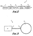
- FIG. 2 presents a schematic illustration of an electric motor monitoring system, generally depicted at 6.
- the electric motor monitoring system 6 employs a computer interfacing and data acquisition method to capture and process arcing events within an electric motor 1.
- the electric motor monitoring system 6 can be seen to comprise a balanced screened loop antenna 7 that includes a matching and signal conditioning unit (not shown), an anti aliasing filter 8, an analogue to digital signal converter (ADC) 9, a high speed PCI card 10 and a computer processor 11 for analysing the sampled data.
- ADC analogue to digital signal converter
- the electric motor monitoring system 6 further comprises an amplifier (not shown).
- the high speed PCI card 10 is capable of capturing and saving several million points of data to the computer processor 11 for subsequent analysis. The further processing required depends on what particular parameter requires to be measured, as described in further detail below.
- the balanced screened loop antenna 7 comprises a loop section 12 and a frequency matching tuning unit 13.
- the loop section 12 is constructed from a conductor 14 and a screened coaxial cable 15.
- the conductor 14 is arranged such that it loops back on itself with the end being attached to the screen of the coaxial cable 15 at the start of the loop section 12.
- the screen of the coaxial cable 15 is deployed such that it extends in two directions from the start of the loop section 12 with a small gap being left at the far end.
- Employing the frequency matching tuning unit 13 allows the electric motor monitoring system 6 to be optimised for use with a particular electric motor 1 or to be altered for frequency selectivity for use with multiple electric motors.
- Optimising the frequency selection of the balanced screened loop antenna 7 for a particular electric motor design and geometry has the advantage of optimising the arcing event signal characteristics for the particular fault conditions as outlined below.
- the multi-turn screened loop antenna comprises a number of screen coiled loops with a small gap in the cable screen being at the furthest point of the coiled loops.
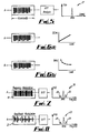
- Figure 4 highlights the significant advantage of employing the balanced screened loop antenna 7 over those previously described in the Prior Art.
- Antennas employed in the Prior Art are designed to receive continuous broadcast signals. Therefore, employing such an antenna with the present system provides a measured RF signal that is a combination of both the desired electric motor signal and any unwanted broadcast signal as shown in Figure 4(a).
- a further problem of employing the antennas taught in the Prior Art for such a measurement is their susceptibility to ringing when an RF impulse is received.
- the antenna inductance, stray capacitance and the associated receiver input impedance circuitry create a tuned circuit that can cause prolonged ringing.
- the duration of the prolonged ringing becomes problematic if the antenna is used to measure the speed of an electric motor (as described below). Ideally it desired that antenna signal oscillations should be completely damped before the next arcing event occurs.
- the ADC 9, high speed PCI card 10 and computer processor 11 can be employed to calculate the speed of the electric motor 1.
- FFT Fast Fourier Transform
- Figure 5 schematically presents the FFT carried out by the electric motor monitoring system 6 with the resultant speed representation depicted at 17.
- the high speed PCI card 10 and computer processor 11 provide estimates of the applied load or torque on the electric motor 1. It is found that a percentage of the detected arcing event signal, above a comparator level, is directly proportional to the applied load or torque. Therefore, by calculating the average width of the arcing event signal, over several thousand arcing events 16, provides a measure of the applied load or torque on the electric motor 1. The relationship between the width of the arcing event 16 and the applied load or torque is presented in Figure 6(a).
- the ratio of the width to height is sensitive to load or torque variations. Therefore, calculating the width to height ratio provides an ideal diagnostic for monitoring such variations in the applied load or torque.
- the described embodiment of the electric motor monitoring system 6 also provides a means for evaluating possible mechanical eccentricity variations on the axis of rotation of the electric motor 1. This may be carried out both at the installation stage as well as during servicing of the motor 1 so allow the efficiency of the electric motor 1 to be optimised.
- FFT of an amplitude modulated data sample 21 produces a frequency spectrum 22 with side bands 23 that are indicative of friction variations within the motor e.g. within the bearings, in the clutch mechanism, or due to imbalances in the load etc.
- a further embodiment of the electric motor monitoring system 6 employs a current measuring technique 24, as shown in Figure 10, for calibrating the electric motor monitoring system 6.
- Calibration employs the RF antenna torque measuring technique (T1) as described in Figure 6(a) and the measurement of the current I through the electric motor 1.
- K the torque constant
- T2 the applied torque
- these two methods should provide the same value for the applied torque. Any difference between these values is indicative of contamination within the motor 1 thus, the offset (T2-T1) can thereafter be added to the T1 torque value to compensate for any contamination.
- the described electric motor monitoring system 6 is an ideal means for testing an electric motor 1 at the end of a manufacturing process. It provides for checking the functionality of the interpoles, decoupling capacitors and for identifying obvious manufacturing faults such as poor connectors.
- the present invention offers several inherent advantages over the Prior Art. It can be employed to measure speed, acceleration and torque of the associated the electric motor 1. Employment of the balanced screened loop antenna 7 significantly improves the signal to noise ratio of the RF detected signals and so provides more accurate readings of these diagnostics.
- a second advantage of the present invention is that the employment of FFT techniques provides a means for measuring and locating both electrical and mechanical faults within the electric motor 1.
- a further advantage of the present invention is that it provides an electric motor monitoring system 6 that provides portable, adjustable and non-intrusive measurement of various diagnostics of the electric motor 1. Therefore, the electric motor monitoring system 6 does not require the electric motor 1 to be stopped for installation purposes. In addition, where it is required to monitor a large number of electric motors it is possible to employ the same system that can simply be located and frequency matched, in turn, to each individual electric motor.
- a yet further advantage of the electric motor monitoring system 6 is that when used in conjunction with standard torque measurement techniques it provides a means for self calibration and compensation to take account of contamination within the electric motor 1.
Landscapes
- Physics & Mathematics (AREA)
- General Physics & Mathematics (AREA)
- Tests Of Circuit Breakers, Generators, And Electric Motors (AREA)
- Control Of Electric Motors In General (AREA)
- Control Of Multiple Motors (AREA)
- Control Of Ac Motors In General (AREA)
- Control Of Motors That Do Not Use Commutators (AREA)
Claims (27)
- Système de contrôle de moteur électrique comprenant une antenne, un moyen d'échantillonnage de données et un moyen de traitement de données et le système fournit un diagnostic pour contrôler le fonctionnement des composants mécaniques et électriques du moteur électrique, caractérisé en ce que l'antenne fournit un moyen pour détecter un signal radioélectrique généré par des événements d'arc provenant d'un contact des balais du moteur électrique.
- Système de contrôle de moteur électrique suivant la revendication 1 dans lequel l'antenne comprend un moyen pour faire écran au bruit de fond, améliorant ainsi le rapport signal/bruit global du système de contrôle de moteur électrique.
- Système de contrôle de moteur électrique suivant la revendication 1 ou 2 dans lequel l'antenne comprend en outre une unité d'adaptation de fréquence de sorte que l'unité d'adaptation de fréquence permet que l'antenne soit réglée en fréquence de manière à optimiser son fonctionnement en fonction du moteur électrique.
- Système de contrôle de moteur électrique suivant la revendication 3 dans lequel l'unité d'adaptation de fréquence comprend une unité de mise en forme de signaux.
- Système de contrôle de moteur électrique suivant l'une quelconque des revendications précédentes dans lequel l'antenne comprend une antenne cadre à écran de Faraday symétrique.
- Système de contrôle de moteur électrique suivant l'une quelconque des revendications 1 à 4 dans lequel l'antenne comprend une antenne cadre à écran de Faraday asymétrique.
- Système de contrôle de moteur électrique suivant l'une quelconque des revendications précédentes dans lequel l'antenne comprend une sonde de champ électrique ou une sonde de champ magnétique.
- Système de contrôle de moteur électrique suivant l'une quelconque des revendications précédentes dans lequel le moyen d'échantillonnage de données comprend un filtre antirepliement de spectre, un convertisseur analogique/numérique et une carte PCI rapide de sorte que le moyen d'échantillonnage de données permet que le signal à haute fréquence soit, sur un laps de temps prédéterminé, capturé.
- Système de contrôle de moteur électrique suivant la revendication 8 dans lequel le moyen de traitement de données comprend en outre un processeur d'ordinateur capable de manipuler et de stocker les données capturées.
- Antenne pour mesurer des signaux radioélectriques à haute fréquence associés à des événements d'arc provenant d'un contact des balais dans un moteur électrique, l'antenne comprenant un cadre et un écran de cadre, dans laquelle l'écran de cadre protège le cadre du bruit de fond, améliorant ainsi le rapport signal/bruit du signal détecté par l'antenne, caractérisée en ce que l'écran de cadre couvre physiquement l'ensemble du cadre, à l'exception d'une petite section de détection.
- Antenne suivant la revendication 10 dans laquelle l'antenne comprend en outre une unité d'adaptation de fréquence de sorte que l'unité d'adaptation de fréquence permet que l'antenne soit réglée en fréquence de manière à optimiser le fonctionnement de l'antenne en fonction du moteur électrique.
- Antenne suivant la revendication 11 dans laquelle l'unité d'adaptation de fréquence comprend une unité de mise en forme de signaux.
- Antenne suivant l'une quelconque des revendications 10 à 12 dans laquelle le cadre comprend un conducteur et un câble coaxial blindé de sorte que le conducteur se retourne sur lui-même de manière à former une ou plusieurs spires tandis que l'extrémité du câble conducteur est rattachée à l'écran du câble coaxial.
- Procédé de diagnostic permettant de contrôler le fonctionnement des composants mécaniques et électriques associés à un moteur électrique, le procédé comprenant les étapes suivantes :i) la détection de signaux radioélectriques à haute fréquence associés à des événements d'arc provenant d'un contact des balais dans le moteur électrique ;ii) l'échantillonnage du signal à haute fréquence sur un laps de temps prédéterminé ;iii) le traitement des données échantillonnées de manière à fournir des informations concernant les composants mécaniques et électriques du moteur électrique.
- Procédé de diagnostic suivant la revendication 14 dans lequel le procédé fournit un moyen pour associer la fréquence du signal à haute fréquence à des composants individuels du moteur électrique.
- Procédé de diagnostic suivant la revendication 14 ou 15 dans lequel la détection des signaux à haute fréquence utilise une antenne non intrusive.
- Procédé de diagnostic suivant l'une quelconque des revendications 14 à 16 dans lequel l'échantillonnage fournit un moyen pour contrôler la modulation de fréquence et la modulation d'amplitude des signaux à haute fréquence.
- Procédé de diagnostic suivant l'une quelconque des revendications 14 à 17 dans lequel le traitement des données échantillonnées comprend l'application de transformées de Fourier rapides de manière à convertir les données échantillonnées en spectres de fréquences interprétables.
- Procédé de diagnostic suivant l'une quelconque des revendications 14 à 17 dans lequel le traitement des données échantillonnées comprend l'application de techniques de traitement de signal numérique sur les données échantillonnées de manière à convertir les données échantillonnées en spectres de fréquences interprétables.
- Procédé de diagnostic suivant la revendication 19 dans lequel les techniques de traitement de signal numérique comprennent une analyse par ondelettes.
- Procédé de diagnostic suivant l'une quelconque des revendications 18 à 20 dans lequel les spectres de fréquences interprétables comprennent des caractéristiques fréquentielles qui peuvent être directement associées à des diagnostics particuliers des composants mécaniques ou électriques du moteur électrique.
- Procédé de diagnostic suivant l'une quelconque des revendications 18 à 21 dans lequel les spectres de fréquences interprétables comprennent des caractéristiques fréquentielles qui peuvent être directement associées à des défaillances mécaniques ou électriques particulières du moteur électrique.
- Procédé de diagnostic suivant l'une quelconque des revendications 14 à 17 dans lequel le traitement des données échantillonnées comprend le calcul d'une largeur moyenne des signaux à haute fréquence, au-dessus d'un niveau prédéterminé, sur un certain nombre d'événements d'arc.
- Procédé de diagnostic suivant l'une quelconque des revendications 14 à 17 dans lequel le traitement des données échantillonnées comprend le calcul d'une hauteur moyenne des signaux à haute fréquence sur un certain nombre d'événements d'arc.
- Procédé de diagnostic suivant l'une quelconque des revendications 14 à 17 dans lequel le traitement des données échantillonnées comprend le calcul d'un rapport moyen de la largeur et de la hauteur des signaux à haute fréquence sur un certain nombre d'événements d'arc.
- Procédé de diagnostic suivant l'une quelconque des revendications 14 à 25 dans lequel le procédé comprend une étape d'auto-étalonnage du procédé de diagnostic.
- Procédé de diagnostic suivant la revendication 26 dans lequel l'auto-étalonnage du procédé de diagnostic comprend une technique de mesure de courant comprenant les sous-étapes suivantes :i) la mesure du couple du moteur électrique en utilisant l'antenne non intrusive ;ii) la mesure directe du courant dans le moteur électrique de manière à permettre que le couple du moteur électrique soit calculé ;iii) le calcul de la différence entre les deux procédés pour obtenir la valeur du couple du moteur électrique, fournissant ainsi un facteur de compensation, etiv) l'addition du facteur de compensation au procédé utilisant l'antenne non intrusive pour mesurer le couple du moteur électrique.
Applications Claiming Priority (3)
| Application Number | Priority Date | Filing Date | Title |
|---|---|---|---|
| GB0200867 | 2002-01-15 | ||
| GBGB0200867.0A GB0200867D0 (en) | 2002-01-15 | 2002-01-15 | Electric motor monitoring system |
| PCT/GB2003/000099 WO2003060536A1 (fr) | 2002-01-15 | 2003-01-13 | Systeme de surveillance pour moteur electrique |
Publications (2)
| Publication Number | Publication Date |
|---|---|
| EP1468302A1 EP1468302A1 (fr) | 2004-10-20 |
| EP1468302B1 true EP1468302B1 (fr) | 2005-08-17 |
Family
ID=9929121
Family Applications (1)
| Application Number | Title | Priority Date | Filing Date |
|---|---|---|---|
| EP03700867A Expired - Lifetime EP1468302B1 (fr) | 2002-01-15 | 2003-01-13 | Systeme de surveillance pour moteur electrique |
Country Status (7)
| Country | Link |
|---|---|
| US (1) | US20050104616A1 (fr) |
| EP (1) | EP1468302B1 (fr) |
| AT (1) | ATE302421T1 (fr) |
| AU (1) | AU2003202013A1 (fr) |
| DE (1) | DE60301329T2 (fr) |
| GB (1) | GB0200867D0 (fr) |
| WO (1) | WO2003060536A1 (fr) |
Cited By (4)
| Publication number | Priority date | Publication date | Assignee | Title |
|---|---|---|---|---|
| WO2009109692A1 (fr) * | 2008-03-07 | 2009-09-11 | Nokia Corporation | Dispositif détecteur d'interférence électromagnétique et procédé et programme d'ordinateur |
| RU2551429C1 (ru) * | 2013-11-26 | 2015-05-27 | Федеральное государственное бюджетное образовательное учреждение высшего профессионального образования "Дальневосточный государственный университет путей сообщения" (ДВГУПС) | Способ диагностики состояния коммутации коллекторных электрических машин |
| US10403116B2 (en) | 2017-06-20 | 2019-09-03 | General Electric Company | Electrical signature analysis of electrical rotating machines |
| US10928814B2 (en) | 2017-02-24 | 2021-02-23 | General Electric Technology Gmbh | Autonomous procedure for monitoring and diagnostics of machine based on electrical signature analysis |
Families Citing this family (19)
| Publication number | Priority date | Publication date | Assignee | Title |
|---|---|---|---|---|
| DE602006008423D1 (de) * | 2006-03-13 | 2009-09-24 | Skf Ab | Verfahren und Gerät zum Anzeigen elektrischer Entladungen in einem Lager eines elektrischen Antriebssystems |
| US7750646B2 (en) * | 2008-01-10 | 2010-07-06 | General Electric Company | Detector for precursive detection of electrical arc |
| DE102008001183A1 (de) * | 2008-04-15 | 2009-10-29 | Alstom Technology Ltd. | Verfahren zur Überwachung einer elektrodynamischen Maschine |
| EP2279548B1 (fr) * | 2008-04-21 | 2015-09-16 | ABB Research Ltd. | Détecteur d'arc et procédé associé pour détecter des arcs indésirables |
| CN102109582A (zh) * | 2009-12-25 | 2011-06-29 | 鸿富锦精密工业(深圳)有限公司 | 线性电压产生装置 |
| DE102010002296A1 (de) * | 2010-02-24 | 2011-08-25 | Siemens Aktiengesellschaft, 80333 | Auswertungsverfahren für Lichtbogenentladungen und zugehöriger Prüfstand |
| WO2011103883A1 (fr) * | 2010-02-24 | 2011-09-01 | Siemens Aktiengesellschaft | Procédé de détection de courants de palier entraînant une formation de plasma |
| DE102011001121B4 (de) * | 2011-03-07 | 2024-03-21 | Dr. Ing. H.C. F. Porsche Aktiengesellschaft | Vorrichtung und Verfahren zur Geräuscherzeugung für ein Kraftfahrzeug |
| US9075115B2 (en) * | 2011-08-31 | 2015-07-07 | General Electric Company | Systems and methods for monitoring the health of an electrical system |
| US8779928B2 (en) * | 2012-05-03 | 2014-07-15 | General Electric Company | Systems and methods to detect generator collector flashover |
| US9393637B2 (en) * | 2013-09-12 | 2016-07-19 | Lincoln Global, Inc. | Brush maintenance system for engine driven welder |
| US9514421B2 (en) * | 2014-03-10 | 2016-12-06 | Regal Beloit America, Inc. | System and method for decommissioning a motor |
| RU2554107C1 (ru) * | 2014-04-01 | 2015-06-27 | Акционерное общество "Федеральный научно-производственный центр "Нижегородский научно-исследовательский институт радиотехники" (АО "ФНПЦ ИИРТ") | Способ и система управления электродвигателем вращения антенны рлс |
| US10121349B2 (en) | 2016-09-21 | 2018-11-06 | General Electric-Technology GMBH | Machine protection and diagnostic systems and methods |
| CN107402342B (zh) * | 2017-08-03 | 2020-04-07 | 杭州柯林电气股份有限公司 | 一种局部放电特高频传感器的信号调节保护装置及方法 |
| DE102017125890A1 (de) * | 2017-11-06 | 2019-05-09 | Ebm-Papst Mulfingen Gmbh & Co. Kg | Verfahren zur Überwachung von Wälzlagern |
| RU2677690C1 (ru) * | 2018-03-06 | 2019-01-21 | Акционерное общество "Федеральный научно-производственный центр "Нижегородский научно-исследовательский институт радиотехники" | Система управления электродвигателем вращения антенны рлс |
| CN110297179B (zh) * | 2018-05-11 | 2024-10-22 | 北部湾大学 | 基于集成深度学习的柴油发电机故障预测与监测系统装置 |
| CN115362379A (zh) * | 2020-03-24 | 2022-11-18 | 舍弗勒技术股份两合公司 | 用于检测由于旋转的机器/系统部件的静电充电而在滚动轴承中发生的电流脉冲的方法和装置 |
Family Cites Families (22)
| Publication number | Priority date | Publication date | Assignee | Title |
|---|---|---|---|---|
| JPS56111326A (en) * | 1980-02-08 | 1981-09-03 | Hitachi Ltd | Antenna circuit of am radio receiver |
| GB2112579A (en) * | 1981-09-10 | 1983-07-20 | Nat Res Dev | Multiband dipoles and ground plane antennas |
| US4866455A (en) * | 1985-01-10 | 1989-09-12 | Lichtblau G J | Antenna system for magnetic and resonant circuit detection |
| DE3543927A1 (de) * | 1985-12-12 | 1987-06-19 | Kraftwerk Union Ag | Verfahren zur teilentladungserfassung und abreissfunkenmessung bei dynamoelektrischen hochspannungsmaschinen sowie einrichtung zu seiner durchfuehrung |
| US4972198A (en) * | 1987-08-31 | 1990-11-20 | Monarch Marking Systems, Inc. | Multiple loop antenna |
| US4999641A (en) * | 1989-09-01 | 1991-03-12 | Monarch Marking Systems, Inc. | Magnetic antenna system having independently controllable electrical field shielding and magnetic field balance |
| US5208542A (en) * | 1991-03-28 | 1993-05-04 | Eaton Corporation | Timing window arc detection |
| US5461329A (en) * | 1992-01-21 | 1995-10-24 | Martin Marietta Energy Systems, Inc. | Method and apparatus for generating motor current spectra to enhance motor system fault detection |
| US5729145A (en) * | 1992-07-30 | 1998-03-17 | Siemens Energy & Automation, Inc. | Method and apparatus for detecting arcing in AC power systems by monitoring high frequency noise |
| US5434509A (en) * | 1992-07-30 | 1995-07-18 | Blades; Frederick K. | Method and apparatus for detecting arcing in alternating-current power systems by monitoring high-frequency noise |
| US5432455A (en) * | 1992-07-30 | 1995-07-11 | Blades; Frederick K. | Method and apparatus for detecting arcing in alternating current power systems by monitoring high-frequency noise |
| US5578931A (en) * | 1993-10-15 | 1996-11-26 | The Texas A & M University System | ARC spectral analysis system |
| US5737026A (en) * | 1995-02-28 | 1998-04-07 | Nielsen Media Research, Inc. | Video and data co-channel communication system |
| US7236816B2 (en) * | 1996-04-25 | 2007-06-26 | Johns Hopkins University | Biopsy and sampling needle antennas for magnetic resonance imaging-guided biopsies |
| US6138078A (en) * | 1996-08-22 | 2000-10-24 | Csi Technology, Inc. | Machine monitor with tethered sensors |
| US6043664A (en) * | 1997-06-06 | 2000-03-28 | General Electric Company | Method and apparatus for turn fault detection in multi-phase AC motors |
| US6362629B1 (en) * | 1997-08-14 | 2002-03-26 | Hendry Mechanical Works | Electric arc monitoring systems |
| US6332961B1 (en) * | 1997-09-17 | 2001-12-25 | Tokyo Electron Limited | Device and method for detecting and preventing arcing in RF plasma systems |
| US6434512B1 (en) * | 1998-04-02 | 2002-08-13 | Reliance Electric Technologies, Llc | Modular data collection and analysis system |
| US6772077B1 (en) * | 1998-08-10 | 2004-08-03 | Hendry Mechanical Works | Electric arc monitoring systems |
| US6701274B1 (en) * | 1999-08-27 | 2004-03-02 | Rosemount Inc. | Prediction of error magnitude in a pressure transmitter |
| US6262550B1 (en) * | 1999-12-17 | 2001-07-17 | General Electric Company | Electrical motor monitoring system and method |
-
2002
- 2002-01-15 GB GBGB0200867.0A patent/GB0200867D0/en not_active Ceased
-
2003
- 2003-01-13 WO PCT/GB2003/000099 patent/WO2003060536A1/fr not_active Ceased
- 2003-01-13 AT AT03700867T patent/ATE302421T1/de not_active IP Right Cessation
- 2003-01-13 EP EP03700867A patent/EP1468302B1/fr not_active Expired - Lifetime
- 2003-01-13 AU AU2003202013A patent/AU2003202013A1/en not_active Abandoned
- 2003-01-13 US US10/501,377 patent/US20050104616A1/en not_active Abandoned
- 2003-01-13 DE DE60301329T patent/DE60301329T2/de not_active Expired - Lifetime
Cited By (5)
| Publication number | Priority date | Publication date | Assignee | Title |
|---|---|---|---|---|
| WO2009109692A1 (fr) * | 2008-03-07 | 2009-09-11 | Nokia Corporation | Dispositif détecteur d'interférence électromagnétique et procédé et programme d'ordinateur |
| US8032330B2 (en) | 2008-03-07 | 2011-10-04 | Nokia Corporation | Electromagnetic interference sensor device and method and computer program |
| RU2551429C1 (ru) * | 2013-11-26 | 2015-05-27 | Федеральное государственное бюджетное образовательное учреждение высшего профессионального образования "Дальневосточный государственный университет путей сообщения" (ДВГУПС) | Способ диагностики состояния коммутации коллекторных электрических машин |
| US10928814B2 (en) | 2017-02-24 | 2021-02-23 | General Electric Technology Gmbh | Autonomous procedure for monitoring and diagnostics of machine based on electrical signature analysis |
| US10403116B2 (en) | 2017-06-20 | 2019-09-03 | General Electric Company | Electrical signature analysis of electrical rotating machines |
Also Published As
| Publication number | Publication date |
|---|---|
| WO2003060536A1 (fr) | 2003-07-24 |
| DE60301329T2 (de) | 2006-06-01 |
| DE60301329D1 (de) | 2005-09-22 |
| AU2003202013A1 (en) | 2003-07-30 |
| US20050104616A1 (en) | 2005-05-19 |
| GB0200867D0 (en) | 2002-03-06 |
| EP1468302A1 (fr) | 2004-10-20 |
| ATE302421T1 (de) | 2005-09-15 |
Similar Documents
| Publication | Publication Date | Title |
|---|---|---|
| EP1468302B1 (fr) | Systeme de surveillance pour moteur electrique | |
| US7102379B2 (en) | Apparatus and method for monitoring and/or analysis of electrical machines during operation | |
| US7649470B2 (en) | Method and apparatus for detection of brush sparking and spark erosion on electrical machines | |
| CN100549636C (zh) | 检测在电机上轴系振动的方法和装置 | |
| AU695413B2 (en) | Monitoring of internal partial discharges on a power transformer | |
| US5739698A (en) | Machine fault detection using slot pass frequency flux measurements | |
| US20050035768A1 (en) | Method and electromagnetic sensor for measuring partial discharges in windings of electrical devices | |
| CA2498105C (fr) | Procede et dispositif pour detecter des etincelles aux balais et de l'erosion par etincelles dans des machines electriques | |
| US20100277199A1 (en) | System For Diagnosing Defects in Electric Motors | |
| CN102721903A (zh) | 发电机转子绕组匝间绝缘故障的检测装置及检测方法 | |
| Itoh et al. | New noise rejection techniques on pulse-by-pulse basis for on-line partial discharge measurement of turbine generators | |
| EP1418437A1 (fr) | Procédé et capteur électromagnétique pour mesurer des décharges partielles dans des enroulements des machines électriques | |
| Pemen | Detection of partial discharges in stator windings of turbine generators | |
| JP3874898B2 (ja) | X線管陽極駆動装置のロータ速度を監視する方法および速度監視装置 | |
| JP3854783B2 (ja) | 部分放電診断装置 | |
| Kumar et al. | Static eccentricity failure diagnosis for induction machine using wavelet analysis | |
| KR102670482B1 (ko) | 고압 회전기기의 절연진단을 위한 부분방전 측정방법 | |
| CN121596157B (zh) | 发电机定子绕组匝间短路检测方法及系统 | |
| Wu et al. | Detection of induction motor operation condition by acoustic signal | |
| Cullen et al. | Application of a radio frequency antenna technique for monitoring the speed, torque and internal fault conditions of AC and DC electric motors | |
| Culbert et al. | On-line measurement of partial discharges on large motors in a generating station | |
| JP2011002313A (ja) | 部分放電検査方法および回転電機 | |
| JPH04296672A (ja) | 回転電機の異常検出装置 | |
| JPH01191072A (ja) | 回転電機の監視方法 | |
| Zhu et al. | On-line PD testing on lower-voltage rotating machines using high sensitivity capacitors |
Legal Events
| Date | Code | Title | Description |
|---|---|---|---|
| PUAI | Public reference made under article 153(3) epc to a published international application that has entered the european phase |
Free format text: ORIGINAL CODE: 0009012 |
|
| 17P | Request for examination filed |
Effective date: 20040813 |
|
| AK | Designated contracting states |
Kind code of ref document: A1 Designated state(s): AT BE BG CH CY CZ DE DK EE ES FI FR GB GR HU IE IT LI LU MC NL PT SE SI SK TR |
|
| AX | Request for extension of the european patent |
Extension state: AL LT LV MK RO |
|
| GRAP | Despatch of communication of intention to grant a patent |
Free format text: ORIGINAL CODE: EPIDOSNIGR1 |
|
| GRAS | Grant fee paid |
Free format text: ORIGINAL CODE: EPIDOSNIGR3 |
|
| GRAA | (expected) grant |
Free format text: ORIGINAL CODE: 0009210 |
|
| AK | Designated contracting states |
Kind code of ref document: B1 Designated state(s): AT BE BG CH CY CZ DE DK EE ES FI FR GB GR HU IE IT LI LU MC NL PT SE SI SK TR |
|
| PG25 | Lapsed in a contracting state [announced via postgrant information from national office to epo] |
Ref country code: IT Free format text: LAPSE BECAUSE OF FAILURE TO SUBMIT A TRANSLATION OF THE DESCRIPTION OR TO PAY THE FEE WITHIN THE PRESCRIBED TIME-LIMIT;WARNING: LAPSES OF ITALIAN PATENTS WITH EFFECTIVE DATE BEFORE 2007 MAY HAVE OCCURRED AT ANY TIME BEFORE 2007. THE CORRECT EFFECTIVE DATE MAY BE DIFFERENT FROM THE ONE RECORDED. Effective date: 20050817 Ref country code: SK Free format text: LAPSE BECAUSE OF FAILURE TO SUBMIT A TRANSLATION OF THE DESCRIPTION OR TO PAY THE FEE WITHIN THE PRESCRIBED TIME-LIMIT Effective date: 20050817 Ref country code: NL Free format text: LAPSE BECAUSE OF FAILURE TO SUBMIT A TRANSLATION OF THE DESCRIPTION OR TO PAY THE FEE WITHIN THE PRESCRIBED TIME-LIMIT Effective date: 20050817 Ref country code: LI Free format text: LAPSE BECAUSE OF FAILURE TO SUBMIT A TRANSLATION OF THE DESCRIPTION OR TO PAY THE FEE WITHIN THE PRESCRIBED TIME-LIMIT Effective date: 20050817 Ref country code: EE Free format text: LAPSE BECAUSE OF FAILURE TO SUBMIT A TRANSLATION OF THE DESCRIPTION OR TO PAY THE FEE WITHIN THE PRESCRIBED TIME-LIMIT Effective date: 20050817 Ref country code: AT Free format text: LAPSE BECAUSE OF FAILURE TO SUBMIT A TRANSLATION OF THE DESCRIPTION OR TO PAY THE FEE WITHIN THE PRESCRIBED TIME-LIMIT Effective date: 20050817 Ref country code: FI Free format text: LAPSE BECAUSE OF FAILURE TO SUBMIT A TRANSLATION OF THE DESCRIPTION OR TO PAY THE FEE WITHIN THE PRESCRIBED TIME-LIMIT Effective date: 20050817 Ref country code: CZ Free format text: LAPSE BECAUSE OF FAILURE TO SUBMIT A TRANSLATION OF THE DESCRIPTION OR TO PAY THE FEE WITHIN THE PRESCRIBED TIME-LIMIT Effective date: 20050817 Ref country code: BE Free format text: LAPSE BECAUSE OF FAILURE TO SUBMIT A TRANSLATION OF THE DESCRIPTION OR TO PAY THE FEE WITHIN THE PRESCRIBED TIME-LIMIT Effective date: 20050817 Ref country code: CH Free format text: LAPSE BECAUSE OF FAILURE TO SUBMIT A TRANSLATION OF THE DESCRIPTION OR TO PAY THE FEE WITHIN THE PRESCRIBED TIME-LIMIT Effective date: 20050817 Ref country code: TR Free format text: LAPSE BECAUSE OF FAILURE TO SUBMIT A TRANSLATION OF THE DESCRIPTION OR TO PAY THE FEE WITHIN THE PRESCRIBED TIME-LIMIT Effective date: 20050817 Ref country code: SI Free format text: LAPSE BECAUSE OF FAILURE TO SUBMIT A TRANSLATION OF THE DESCRIPTION OR TO PAY THE FEE WITHIN THE PRESCRIBED TIME-LIMIT Effective date: 20050817 |
|
| REG | Reference to a national code |
Ref country code: GB Ref legal event code: FG4D |
|
| REG | Reference to a national code |
Ref country code: CH Ref legal event code: EP |
|
| REG | Reference to a national code |
Ref country code: IE Ref legal event code: FG4D |
|
| REF | Corresponds to: |
Ref document number: 60301329 Country of ref document: DE Date of ref document: 20050922 Kind code of ref document: P |
|
| PG25 | Lapsed in a contracting state [announced via postgrant information from national office to epo] |
Ref country code: SE Free format text: LAPSE BECAUSE OF FAILURE TO SUBMIT A TRANSLATION OF THE DESCRIPTION OR TO PAY THE FEE WITHIN THE PRESCRIBED TIME-LIMIT Effective date: 20051117 Ref country code: BG Free format text: LAPSE BECAUSE OF FAILURE TO SUBMIT A TRANSLATION OF THE DESCRIPTION OR TO PAY THE FEE WITHIN THE PRESCRIBED TIME-LIMIT Effective date: 20051117 Ref country code: GR Free format text: LAPSE BECAUSE OF FAILURE TO SUBMIT A TRANSLATION OF THE DESCRIPTION OR TO PAY THE FEE WITHIN THE PRESCRIBED TIME-LIMIT Effective date: 20051117 Ref country code: DK Free format text: LAPSE BECAUSE OF FAILURE TO SUBMIT A TRANSLATION OF THE DESCRIPTION OR TO PAY THE FEE WITHIN THE PRESCRIBED TIME-LIMIT Effective date: 20051117 |
|
| PG25 | Lapsed in a contracting state [announced via postgrant information from national office to epo] |
Ref country code: ES Free format text: LAPSE BECAUSE OF FAILURE TO SUBMIT A TRANSLATION OF THE DESCRIPTION OR TO PAY THE FEE WITHIN THE PRESCRIBED TIME-LIMIT Effective date: 20051128 |
|
| PG25 | Lapsed in a contracting state [announced via postgrant information from national office to epo] |
Ref country code: PT Free format text: LAPSE BECAUSE OF FAILURE TO SUBMIT A TRANSLATION OF THE DESCRIPTION OR TO PAY THE FEE WITHIN THE PRESCRIBED TIME-LIMIT Effective date: 20060117 |
|
| PG25 | Lapsed in a contracting state [announced via postgrant information from national office to epo] |
Ref country code: MC Free format text: LAPSE BECAUSE OF NON-PAYMENT OF DUE FEES Effective date: 20060131 Ref country code: LU Free format text: LAPSE BECAUSE OF NON-PAYMENT OF DUE FEES Effective date: 20060131 |
|
| NLV1 | Nl: lapsed or annulled due to failure to fulfill the requirements of art. 29p and 29m of the patents act | ||
| PG25 | Lapsed in a contracting state [announced via postgrant information from national office to epo] |
Ref country code: HU Free format text: LAPSE BECAUSE OF FAILURE TO SUBMIT A TRANSLATION OF THE DESCRIPTION OR TO PAY THE FEE WITHIN THE PRESCRIBED TIME-LIMIT Effective date: 20060218 |
|
| REG | Reference to a national code |
Ref country code: CH Ref legal event code: PL |
|
| ET | Fr: translation filed | ||
| PLBE | No opposition filed within time limit |
Free format text: ORIGINAL CODE: 0009261 |
|
| STAA | Information on the status of an ep patent application or granted ep patent |
Free format text: STATUS: NO OPPOSITION FILED WITHIN TIME LIMIT |
|
| 26N | No opposition filed |
Effective date: 20060518 |
|
| PG25 | Lapsed in a contracting state [announced via postgrant information from national office to epo] |
Ref country code: CY Free format text: LAPSE BECAUSE OF FAILURE TO SUBMIT A TRANSLATION OF THE DESCRIPTION OR TO PAY THE FEE WITHIN THE PRESCRIBED TIME-LIMIT Effective date: 20050817 |
|
| PGFP | Annual fee paid to national office [announced via postgrant information from national office to epo] |
Ref country code: GB Payment date: 20130109 Year of fee payment: 11 Ref country code: IE Payment date: 20130110 Year of fee payment: 11 Ref country code: DE Payment date: 20130109 Year of fee payment: 11 Ref country code: FR Payment date: 20130204 Year of fee payment: 11 |
|
| REG | Reference to a national code |
Ref country code: DE Ref legal event code: R119 Ref document number: 60301329 Country of ref document: DE |
|
| GBPC | Gb: european patent ceased through non-payment of renewal fee |
Effective date: 20140113 |
|
| PG25 | Lapsed in a contracting state [announced via postgrant information from national office to epo] |
Ref country code: DE Free format text: LAPSE BECAUSE OF NON-PAYMENT OF DUE FEES Effective date: 20140801 |
|
| REG | Reference to a national code |
Ref country code: FR Ref legal event code: ST Effective date: 20140930 |
|
| REG | Reference to a national code |
Ref country code: IE Ref legal event code: MM4A |
|
| REG | Reference to a national code |
Ref country code: DE Ref legal event code: R119 Ref document number: 60301329 Country of ref document: DE Effective date: 20140801 |
|
| PG25 | Lapsed in a contracting state [announced via postgrant information from national office to epo] |
Ref country code: GB Free format text: LAPSE BECAUSE OF NON-PAYMENT OF DUE FEES Effective date: 20140113 Ref country code: FR Free format text: LAPSE BECAUSE OF NON-PAYMENT OF DUE FEES Effective date: 20140131 |
|
| PG25 | Lapsed in a contracting state [announced via postgrant information from national office to epo] |
Ref country code: IE Free format text: LAPSE BECAUSE OF NON-PAYMENT OF DUE FEES Effective date: 20140113 |