EP1468592B1 - Geschütztes gehäuse - Google Patents
Geschütztes gehäuse Download PDFInfo
- Publication number
- EP1468592B1 EP1468592B1 EP02775181A EP02775181A EP1468592B1 EP 1468592 B1 EP1468592 B1 EP 1468592B1 EP 02775181 A EP02775181 A EP 02775181A EP 02775181 A EP02775181 A EP 02775181A EP 1468592 B1 EP1468592 B1 EP 1468592B1
- Authority
- EP
- European Patent Office
- Prior art keywords
- drawer
- housing
- protected cabinet
- cabinet
- stopper
- Prior art date
- Legal status (The legal status is an assumption and is not a legal conclusion. Google has not performed a legal analysis and makes no representation as to the accuracy of the status listed.)
- Expired - Lifetime
Links
- 238000005192 partition Methods 0.000 claims description 7
- 238000000034 method Methods 0.000 description 5
- UFULAYFCSOUIOV-UHFFFAOYSA-N cysteamine Chemical compound NCCS UFULAYFCSOUIOV-UHFFFAOYSA-N 0.000 description 2
- 229910000831 Steel Inorganic materials 0.000 description 1
- 230000003213 activating effect Effects 0.000 description 1
- 230000001934 delay Effects 0.000 description 1
- 239000000463 material Substances 0.000 description 1
- 230000000704 physical effect Effects 0.000 description 1
- 230000011664 signaling Effects 0.000 description 1
- 239000010959 steel Substances 0.000 description 1
- 210000000689 upper leg Anatomy 0.000 description 1
Images





Classifications
-
- A—HUMAN NECESSITIES
- A47—FURNITURE; DOMESTIC ARTICLES OR APPLIANCES; COFFEE MILLS; SPICE MILLS; SUCTION CLEANERS IN GENERAL
- A47B—TABLES; DESKS; OFFICE FURNITURE; CABINETS; DRAWERS; GENERAL DETAILS OF FURNITURE
- A47B67/00—Chests; Dressing-tables; Medicine cabinets or the like; Cabinets characterised by the arrangement of drawers
- A47B67/04—Chests of drawers; Cabinets characterised by the arrangement of drawers
-
- A—HUMAN NECESSITIES
- A47—FURNITURE; DOMESTIC ARTICLES OR APPLIANCES; COFFEE MILLS; SPICE MILLS; SUCTION CLEANERS IN GENERAL
- A47B—TABLES; DESKS; OFFICE FURNITURE; CABINETS; DRAWERS; GENERAL DETAILS OF FURNITURE
- A47B88/00—Drawers for tables, cabinets or like furniture; Guides for drawers
- A47B88/70—Coupled drawers
-
- E—FIXED CONSTRUCTIONS
- E05—LOCKS; KEYS; WINDOW OR DOOR FITTINGS; SAFES
- E05G—SAFES OR STRONG-ROOMS FOR VALUABLES; BANK PROTECTION DEVICES; SAFETY TRANSACTION PARTITIONS
- E05G5/00—Bank protection devices
- E05G5/006—Cashier's counters or receptables for holding valuables readily accessible for handling, with safeguard mechanisms for the valuables in case of hold-up
-
- G—PHYSICS
- G07—CHECKING-DEVICES
- G07F—COIN-FREED OR LIKE APPARATUS
- G07F9/00—Details other than those peculiar to special kinds or types of apparatus
- G07F9/06—Coin boxes
-
- G—PHYSICS
- G07—CHECKING-DEVICES
- G07G—REGISTERING THE RECEIPT OF CASH, VALUABLES, OR TOKENS
- G07G1/00—Cash registers
- G07G1/0018—Constructional details, e.g. of drawer, printing means, input means
- G07G1/0027—Details of drawer or money-box
-
- E—FIXED CONSTRUCTIONS
- E05—LOCKS; KEYS; WINDOW OR DOOR FITTINGS; SAFES
- E05Y—INDEXING SCHEME ASSOCIATED WITH SUBCLASSES E05D AND E05F, RELATING TO CONSTRUCTION ELEMENTS, ELECTRIC CONTROL, POWER SUPPLY, POWER SIGNAL OR TRANSMISSION, USER INTERFACES, MOUNTING OR COUPLING, DETAILS, ACCESSORIES, AUXILIARY OPERATIONS NOT OTHERWISE PROVIDED FOR, APPLICATION THEREOF
- E05Y2900/00—Application of doors, windows, wings or fittings thereof
- E05Y2900/20—Application of doors, windows, wings or fittings thereof for furniture, e.g. cabinets
Definitions
- the present invention relates to protection from robbery or theft. More particularly, the present invention relates to a protected cabinet for cash or other items of value.
- a robber enters a bank during working hours, finding the cashier sitting in front of an open cash drawer, and forces the cashier, at gun point, to hand over all the money found in that exposed drawer.
- US Pat. 4,035,792 (Price et al. ), titled CASH REGISTER SECURITY SYSTEM, disclosed a cash register security system having a first latch normally adapted to engage and securely hold within a cash register a false drawer, a release device connected to the first latch for releasing the first latch from engaging and holding the false drawer within the cash register, a second latch adapted to engage and hold within the cash register a cash drawer, the second latch normally being in disengagement with the cash drawer, a locking device connected to the second latch for locking the second latch in engagement with the cash drawer and holding the cash drawer within the cash register, an alarm circuit connected to the release device and the locking device and an alarm switch connected to the alarm circuit for operating the alarm circuit and activating the release device and the locking device whereby the cash drawer is locked within the cash register and only the false drawer may be ejected from the cash register after the alarm switch is operated.
- a police silent alarm, a plurality of cameras and a flashing beacon also are connected to and operated by the alarm switch.
- FR Pat. 2535573 Diemert et al. ) there was disclosed a hidden drawer that normally nests within the drawer cabinet, and upon engagement using a hidden a cable, the hidden drawer is revealed, allowing access to its content.
- US Pat. 6,390,361 disclosed a method of protecting an active cash drawer from robbery comprising the following steps: housing the active cash drawer together with an emergency cash drawer in a housing having a frontal opening to accommodate the opening of a cash drawer; arranging for the active cash drawer to open through the frontal opening in the housing to facilitate routine cash transactions; generating an alarm signal in the event of a robbery and arranging for the emergency cash drawer to open instead of the active cash drawer subsequent to the alarm signal.
- the frontal opening is generally the height of a cash drawer and the cash drawers vertically shift upwards within the housing subsequent to the alarm signal so that the active cash drawer is aligned behind the frontal opening prior to the alarm signal and the emergency cash drawer is in alignment with the frontal opening subsequent thereto.
- JP 04-236694 Tokyo Electric Co. Ltd.
- titled DRAWER DEVICE FOR CASH REGISTER discloses a cabinet featuring a single drawer, which can be opened halfway and can be locked in said position, so that money in the other, unopened half is prevented from being stolen. When releasing the locking mechanism in said half opened position, the drawer can be opened fully.
- US 4,615,095 Bessinger et al.
- titled INCLINED DRAWER SLIDE INCORPORATING SCALE discloses a drawer with an inclined orientation, which ensures the drawer to be self-closing.
- a protected cabinet for cash or other valuables designed to protect the cash or valuables from being robbed, the protected cabinet comprising:
- the drawers are provided with partitions, dividing the drawers into compartments.
- a key lock is provided in order to allow opening of the drawers only when using a key.
- the first drawer has a back portion normally hidden within the housing, and provided with a latching mechanism that in a first state ⁇ prevents fully withdrawing the first drawer, keeping the hidden portion inside the housing, and in a second state releases the hidden portion to be withdrawn and exposed out of the housing.
- the latching mechanism comprising a lever pivotally connected to a partition defining the hidden portion, the lever coupled to an arm having a wedge, so that when the lever is pressed the wedge is lifted over a ligule provided at the bottom of the housing 22, making the withdrawal and exposure of the hidden compartment possible.
- second drawer is prevented from opening when the first drawer is opened, by means of a stopper mechanism.
- the stopper mechanism comprises a lever pivotally coupled to the second drawer at a pivot, the lever having a ligule that may be inserted into a recess in a partition between the first drawer and the second drawer, an end of the lever limited by a stopper protruding inwardly from the housing, and wherein the stopper mechanism is operated to free the second drawer by a latch inserted through the recess, lifting the lever over the stopper.
- the engagement mechanism comprises a latch coupled to the first drawer actuated by a knob provided on the drawer front panel, whereby when the latch is extended it engages into a recess provided in the second drawer, causing the second drawer to be opened when the drawer front panel is pulled, and when it is retracted, it leaves the recess, disengaging the second drawer.
- the operation of the knob is limited by a limiting mechanism so that engaging the second drawer is possible only when the first drawer is retracted into the housing and the drawer front panel covers the opening of the housing.
- the housing is provided with an inclination so that the first drawer is automatically retracted to a closed state, when not held manually.
- a stopper for stopping the retraction of the first drawer caused by the inclination, and leaving the first drawer open for as long as the stopper is used.
- the stopper comprises a plate pivotally attached to the housing coupled to a foot passing through the housing facing the first drawer, so that when the plate is pressed towards the housing the drawer is kept in place.
- a spring is provided in order to remove the foot away from the first drawer when the plate is not pressed.
- Fig. 1 illustrates a protected cabinet in accordance with a preferred embodiment of the present invention.
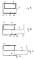
- Figure 4a illustrates a sectional side view of the protected cabinet of Fig. 1 , with the regular and emergency drawers in the closed state.
- Figure 4 b illustrates a sectional side view of the protected cabinet of Fig. 1 , with the regular drawer in an opened state.
- Figure 4 c illustrates a sectional side view of the protected cabinet of Fig. 1 , with the regular drawer in a fully opened state (exposing the hidden compartment of the regular drawer).
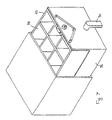
- Figure 5 illustrates a view of the protected cabinet of Fig. 1 , with the regular drawer in a fully opened state.
- Figures 6a, 6b, 6c and 6d illustrate various stages of operation of a security mechanism limiting the operation of the drawer knob.
- Figure 7 illustrate a view of the protected cabinet of Fig. 1 , with the emergency drawer in an open state.
- Figure 8a illustrates a side sectional view of the engagement mechanism for engaging and disengaging the emergency drawer.
- Figure 8b illustrates a top view of the engagement mechanism for engaging and disengaging the emergency drawer.
- Figure 9a illustrates a view of another preferred embodiment of the protected cabinet of the present invention, with the regular drawer in an opened state, provided with a stopper and an inclination.
- Figure 9b illustrates a top sectional view of the protected cabinet of Fig. 9a , showing the operation of the stopper.
- Figures 10a and 10b show a see-through view of a stopper mechanism for preventing opening of the emergency drawer when the regular drawer is in an opened state.
- the protected cabinet of the present invention is aimed at providing a secured cabinet for cash and other valuables, for use by a public service provider, such as a bank teller (hereinafter referred to as "a teller").
- a public service provider such as a bank teller (hereinafter referred to as "a teller").
- An aspect of the present invention is the provision of a regular drawer and an emergency drawer in the cabinet.
- the regular drawer is used by the teller for transactions carried our during the regular course of business.
- an emergency situation namely a robbery
- the teller switches to the emergency drawer, that contains some money and hands it to the robber to appease him, making him believe he got all the content of the cash drawer (the fact that there are two drawers in the cabinet is of course kept a as secret and not revealed to the public).
- Another aspect of the present invention is the provision of such protected cabinet with safety means aimed at preventing opening of the emergency drawer when the regular drawer is opened, in order to avoid inadvertent exposure of the emergency drawer, or opening by a thief or robber that has already got hold of the contents of the regular drawer, and thus preventing soaring of the losses.
- Another aspect of the present invention is the provision of a hidden compartment to the regular drawer, thus allowing safe disposal of cash or valuables in the regular drawer, hidden from the public, and especially from ill-intentioned persons.
- a drawer cabinet 20 comprises a housing 22, preferably made of steel or other rigid durable material, having a drawer front panel 24, on which operation knob 30, handle 28 and key lock 26 are provided. Inside the housing, behind the drawer front panel are provided two drawers (not shown in this Figure. See other Figs.), positioned one over the other.
- One drawer - the bottom drawer, in the drawer cabinet depicted in the drawings - is a drawer used regularly for storing cash or other valuables, being opened and closed by the teller in his usual course of action during his work according to his needs (hereinafter - the regular drawer), and the other drawer - the top drawer in the embodiment shown in the drawings - is an emergency drawer, to be used only in an emergency.
- the drawer front panel 24 substantially and effectively covers the opening of the housing, hiding both drawers behind it, and in.fact does not provide any hint as to the existence of two drawers in the cabinet. It is desired to make the cabinet so that a person not familiar with its design will assume it contains only one drawer.
- Figure 2 illustrates the protected cabinet of Fig. 1 with the regular drawer in an opened state.
- the regular drawer preferably has several divisions within it, dividing the drawer into compartments 34 for keeping different values of bill notes or coins in them.
- the regular drawer has a hidden portion located at the back of the drawer, and is normally inside the housing, a latch mechanism, whose lever 38 is shown, preventing its inadvertent withdrawal and exposure (see also Fig. 3 ).
- Emergency drawer 40 has no markings, or handles or any other kind of indication suggesting it is a drawer, and its front wall appears to be an immobile part of the housing.
- the emergency drawer is preferably provided with a safety mechanism (see Fig. 10 ) preventing its opening, when the regular drawer is opened. This is important in order to avoid a situation where, in a robbery, the robber picks the contents of the regular drawer and in addition opens the emergency drawer and takes what money or valuables that are found there too.
- FIG. 3 illustrates the protected cabinet of Fig. 2 showing the latch mechanism of the hidden compartment.
- Partition 43 divides the regular drawer into two main parts, the regularly accessed by the teller (seen exposed in Fig. 2 ), and a hidden part - the hidden compartment generally not accessed by the teller in the usual course of action.
- Lever 38 is pivotally connected to partition 43, so that when its end is pushed arm 44 is lifted withdrawing wedge 46 from ligule 48, provided at the bottom of the housing 22, making the withdrawal and exposure of the hidden compartment possible.
- Spring 42 is optionally provided, to counter pull lever 38 back to its engaged position, balancing the weight of arm 44.
- Latch 36 is preferably provided, operated by a key inserted in the key lock 26, with a matching recess provided in the top surface of the housing (not shown) so that the drawer cabinet may be opened only when using a key.
- Figure 4a illustrates a sectional side view of the protected cabinet of Fig. 1 , with the regular and emergency drawers in the closed state.
- Figure 4 b illustrates a sectional side view of the protected cabinet of Fig. 1 , with the regular drawer in an opened state.
- Figure 4 c illustrates a sectional side view of the protected cabinet of Fig. 1 , with the regular drawer in a fully opened state (exposing the hidden compartment of the regular drawer).
- Figure 5 illustrates a view of the protected cabinet of Fig. 1 , with the regular drawer in a fully opened state, exposing the hidden compartment 35, and allowing the teller to access it.
- Knob 30 preferably may be operated only when the drawers are closed, preventing any erroneous switching and consequent release of the wrong drawer.
- Figures 6a, 6b, 6c and 6d illustrate various stages of operation of a security mechanism limiting the operation of drawer knob 30.
- Bore 37 has a rectangular shape at its upper end, matching the cross sectional shape of the axle, and a lower wider portion large enough to allow axle 31 to be turned freely when not enclosed by the upper rectangular portion.
- axle 31 fits into the upper rectangular portion of the bore, and thus is limited from turning.
- the length of bar 33 is determined to be such that its lower end 39 extends beyond the lower surface of the housing.
- end 39 is raised by the lower surface of the housing, thus freeing axle 31 from the limiting rectangular portion, allowing the turning of knob 30.
- end 39 is preferably shaped as a wedge to ease its raising by the lower surface of the housing.
- Figure 7 illustrate a view of the protected cabinet of Fig. 1 , with the emergency drawer in an open state.
- knob 30 When knob 30 is turned to engage the emergency drawer, the drawer is engaged to the regular drawer on top, and when the drawer front panel is pulled, the emergency drawer 40 (preferably divided into compartments 34) shows up, revealing its contents, and at the same time covering and concealing the regular drawer 32.
- Figure 8a illustrates a side sectional view of the engagement mechanism for engaging and disengaging the emergency drawer.
- Figure 8b illustrates a top view of the engagement mechanism for engaging and disengaging the emergency drawer.
- Figure 8c illustrates the latch device used in the engagement mechanism of Figs 8a, 8b .
- the axle 31 coupled to knob 30 is used to actuate latch mechanism 50 (in the embodiment shown in the figure, a latch mechanism of the type used for doors is provided), the axle inserted in bore 51 of the latch mechanism 50.
- latch 52 In the engaged mode latch 52 extends over face plate 53, inserted into a matching recess (see 63 in Fig. 10b ) in the bottom of emergency drawer 40 , whereas in the disengaged mode, the latch is retracted letting go of the emergency drawer.
- Figure 9a illustrates a view of another preferred embodiment of the protected cabinet of the present invention, with the regular drawer in an opened state, provided with a stopper and an inclination 60.
- This is aimed at forcing the regular drawer to close, each time the teller releases his hold of the drawer.
- the default state of the drawer, as a result of this inclination, is closed. This way, the teller is less likely to be caught with the regular drawer open when a robber steps into the bank, and in any case, once the drawer is freed it shuts.
- the knob to the emergency mode is turned when the drawer front panel is pulled the emergency drawer emerges.
- Figure 9b illustrates a top sectional view of the protected cabinet of Fig. 9a , showing the operation of the stopper.
- the stopper here in the form of a plate, is pivotally attached to housing 22.
- Foot 58, coupled to the plate is provided, passing through housing 22 facing the regular drawer, so that when the stopper plate is pressed towards the housing (the teller can use his thigh to do so), the drawer is kept in place, preventing its gliding back to the closed position.
- the foot is resiliently retracted (by spring 59), and the drawer if freed to close.
- Figures 10a and 10b show a see-through view of a stopper mechanism for preventing opening of the emergency drawer when the regular drawer is in an opened state.
- the stopper mechanism comprises a lever 62 pivotally coupled to the emergency drawer 40 (at the front wall) at pivot 66 with a ligule 64 that may be inserted in recess 63, the other end of the lever limited by stopper 68 protruding inwardly from housing 22.
- knob 30 may be turned to engage the emergency drawer (see Fig. 8b ), and latch 52 when inserted into recess 63 pushes away ligule 64, lifting lever 62 over stopper 68, and releasing the emergency drawer to be pulled open.
- the protected cabinet of the present invention can incorporate other protection means such as an alarm system, either loud sounding siren, or silent (signaling an emergency signal at a near by police station).
- an alarm system either loud sounding siren, or silent (signaling an emergency signal at a near by police station).
- silent signalling an emergency signal at a near by police station.
- the latter is preferred, as it is an aim of the present invention to prevent risky situation where the robber might loose his temper and act irrationally.
Landscapes
- Physics & Mathematics (AREA)
- General Physics & Mathematics (AREA)
- Business, Economics & Management (AREA)
- Accounting & Taxation (AREA)
- Finance (AREA)
- Drawers Of Furniture (AREA)
- Casings For Electric Apparatus (AREA)
- Cash Registers Or Receiving Machines (AREA)
- Slot Machines And Peripheral Devices (AREA)
Claims (15)
- Geschütztes Gehäuse (20) für Bargeld oder andere Wertsachen, welches so ausgestaltet ist, um das Bargeld oder die anderen Wertsachen vor Raub zu schützen,
wobei das geschützte Gehäuse umfasst,
eine Einhausung (22), um zwei Schubladen (32, 40) aufzunehmen und zu beherbergen, umfassend eine vordere Öffnung, durch welche eine oder beide Schubladen simultan herausgezogen werden können;
eine erste Schublade (32), welche so ausgestaltet ist, dass es in die Einhausung (22) durch die vordere Öffnung eingeschoben und herausgezogen werden kann, und verbunden ist mit einer vorderen Blende (24), welche so ausgestaltet ist, dass sie die vordere Öffnung der Einhausung (22) im wesentlichen abdeckt;
eine zweite Schublade (40), welche oberhalb der ersten Schublade (32) angeordnet ist, und so ausgestaltet ist, dass sie im Falle der festen Verbindung mit der ersten Schublade (32) in die Einhausung (22) durch die vordere Öffnung eingeschoben und herausgezogen werden kann;
einem Verbindungsmechanismus (50), um die zweite Schublade mit der ersten Schublade zu verbinden,
dadurch gekennzeichnet, dass,
der Verbindungsmechanismus (50) einen externen Betätigungsknopf (30) umfasst, welcher nur betätigt werden kann, wenn beide Schubladen (32, 40) geschlossen sind;
und dass die zweite Schublade im Falle der festen Verbindung der zweiten Schublade mit der ersten Schublade, die erste Schublade im wesentlichen abdeckt, um somit den Blick auf den Inhalt der ersten Schublade zu verhindern;
wobei eine Schublade gewöhnlich für Geschäfte oder die Darbietung des in ihr enthaltenen Bargeldes oder der Wertsachen verwendet wird;
wobei die andere Schublade in Gefahrsituationen, wie zum Beispiel einem Raubüberfall, durch Auslösung des Verbindungsmechanismus als Notfall- und Köderschublade verwendet wird. - Geschütztes Gehäuse gemäß Anspruch 1,
wobei die Schubladen mit Unterteilungen (43) ausgestattet sind, welche die Schubladen in Fächer unterteilen. - Geschütztes Gehäuse gemäß Anspruch 1,
wobei die vordere Blende mit einem Griff (28) ausgestattet ist. - Geschütztes Gehäuse gemäß Anspruch 1,
wobei ein Schließmechanismus mit Schlüssel (26) bereitgestellt wird, damit die Schubladen nur unter Verwendung eines Schlüssels geöffnet werden können. - Geschütztes Gehäuse gemäß Anspruch 1,
wobei die erste Schublade ein rückwärtiges Abteil aufweist, welches normalerweise in der Einhausung verborgen ist und mit einem Rastmechanismus (46) ausgestattet ist, der in einen ersten Einrastzustand die vollständige Öffnung der ersten Schublade verhindert und sich somit das rückwärtige Abteil innerhalb der Einhausung befindet,
und einem zweiten Einrastzustand das Geheimabteil zur Öffnung freigibt und außerhalb der Einhausung frei zugänglich darbietet. - Geschütztes Gehäuse gemäß Anspruch 5,
wobei der Rastmechanismus einen Schwenkarm (38) umfasst, der drehbar mit einer Unterteilung (43) verbunden ist, welche das Geheimabteil abtrennt,
und wobei der Schwenkarm mit einem Ausleger (44) verbunden ist, welcher seinerseits einen Klemmkeil (46) aufweist, so dass beim Druck auf den Schwenkarm der Klemmkeil über eine am Boden der Einhausung angebrachte Zunge (48) gleitet und somit das Herausziehen und den Zugang zu dem Geheimabteil ermöglicht. - Geschütztes Gehäuse gemäß Anspruch 1,
wobei die Öffnung der zweiten Schublade bei Öffnung der ersten Schublade mit Hilfe eines Stoppermechanismus verhindert wird. - Geschütztes Gehäuse gemäß Anspruch 7,
wobei der Stoppermechanismus einen Schwenkarm (62) umfasst, der drehbar mit der zweiten Schublade an einem Angelpunkt verbunden ist;
und wobei der Schwenkarm eine Zunge (64) aufweist, die in eine Auskehlung (63) in der zweiten Schublade eingeführt werden kann;
und wobei ein Ende des Schwenkarms durch einen Stopper (68) begrenzt wird, welcher von der Einhausung nach innen hineinragt;
und wobei der Stoppermechanismus so betätigt wird, dass die zweite Schublade durch einen durch die Auskehlung hindurch drückenden Schnappriegel (52), welcher den Schwenkarm über den Stopper hinüber hebt, gelöst wird. - Geschütztes Gehäuse gemäß Anspruch 1,
wobei der Verbindungsmechanismus einen Schnappriegel (36) umfasst, welcher mit der ersten Schublade verbunden ist und durch einen Knopf betätigt wird, welcher an der vorderen Blende angebracht ist,
wobei der ausgefahrene Schnappriegel in eine an der Unterseite der zweiten Schublade angebrachte Auskehlung einklinkt, und dafür sorgt, dass die zweite Schublade zusammen mit der ersten Schublade geöffnet wird und der Schnappriegel beim Zurückziehen die Auskehlung verlässt und die zweite Schublade freigibt. - Geschütztes Gehäuse gemäß Anspruch 9,
wobei die Betätigung des Knopfes durch einen Beschränkungsmechanismus (31) so eingeschränkt wird, dass die Verbindung mit der zweiten Schublade nur möglich ist, wenn die erste Schublade in die Einhausung völlig eingeschoben ist und die vordere Blende der Schublade die Öffnung der Einhausung bedeckt. - Geschütztes Gehäuse gemäß Anspruch 10,
wobei der Beschränkungsmechanismus einen Riegel (33) umfasst, welcher eine Bohrung (37) aufweist, durch welche sich eine mit dem Knopf verbundene Achse (31) mit einem polygonen Querschnitt erstreckt,
und wobei die Bohrung so ausgestaltet ist, dass sie im oberen Bohrungsabschnitt dem polygonen Querschnitt gleicht und im unteren Bohrungsabschnitt deutlich größer ist, so dass sich die Achse zwar innerhalb dieses Abschnittes frei drehen kann aber im anderen Falle die Drehung der Achse unmöglich ist,
und wobei sich der Riegel auf eine Länge erstreckt, welche ganz leicht größer ist als jene, die nötig ist, um den Boden der Einhausung zu erreichen, so dass bei Bewegung der vorderen Blende hin zu einem Verschluss der Öffnung der Einhausung der Riegel angehoben wird, so dass sich die Achse frei drehen kann. - Geschütztes Gehäuse gemäß Anspruch 1,
wobei die Einhausung mit einer Abschrägung versehen ist, so dass die erste Schublade automatisch in den geschlossenen Zustand eingezogen wird, wenn sie nicht dauernd manuell festgehalten wird. - Geschütztes Gehäuse gemäß Anspruch 12,
wobei ein Stopper (56) eingesetzt wird, um die durch die Abschrägung der Einhausung erzeugte Schließbewegung der ersten Schublade abzustoppen und die Schublade offen zu halten, solange der Stopper verwendet wird. - Geschütztes Gehäuse gemäß Anspruch 13,
wobei der Stopper eine Platte (56) umfasst, welche drehbar an der Einhausung angebracht ist und mit einem Fuß (58) verbunden ist, welcher durch die Einhausung und der ersten Schublade zugewandt verläuft, so dass die Schublade festgestellt ist, wenn die Platte zum Gehäuse hin gedrückt wird. - Geschütztes Gehäuse gemäß Anspruch 14,
wobei weiterhin eine Feder (59) angebracht ist, um den Fuß von der ersten Schublade weg zu bewegen, wenn die Platte nicht gedrückt wird.
Applications Claiming Priority (5)
| Application Number | Priority Date | Filing Date | Title |
|---|---|---|---|
| IL14732401 | 2001-12-26 | ||
| IL14732401A IL147324A0 (en) | 2001-12-26 | 2001-12-26 | Minimally invasive device |
| IL14800502 | 2002-02-05 | ||
| IL14800502A IL148005A0 (en) | 2002-02-05 | 2002-02-05 | Drawer for money and valuables |
| PCT/IL2002/000802 WO2003056890A1 (en) | 2001-12-26 | 2002-10-02 | Protected cabinet |
Publications (3)
| Publication Number | Publication Date |
|---|---|
| EP1468592A1 EP1468592A1 (de) | 2004-10-20 |
| EP1468592A4 EP1468592A4 (de) | 2006-05-10 |
| EP1468592B1 true EP1468592B1 (de) | 2010-09-01 |
Family
ID=36176983
Family Applications (1)
| Application Number | Title | Priority Date | Filing Date |
|---|---|---|---|
| EP02775181A Expired - Lifetime EP1468592B1 (de) | 2001-12-26 | 2002-10-02 | Geschütztes gehäuse |
Country Status (4)
| Country | Link |
|---|---|
| US (1) | US7261385B2 (de) |
| EP (1) | EP1468592B1 (de) |
| AT (1) | ATE479974T1 (de) |
| DE (1) | DE60237545D1 (de) |
Families Citing this family (38)
| Publication number | Priority date | Publication date | Assignee | Title |
|---|---|---|---|---|
| US7376587B1 (en) | 2000-07-11 | 2008-05-20 | Western Union Financial Services, Inc. | Method for enabling transfer of funds through a computer network |
| US7606734B2 (en) | 2000-07-11 | 2009-10-20 | The Western Union Company | Wide area network person-to-person payment |
| US7117183B2 (en) | 2001-03-31 | 2006-10-03 | First Data Coroporation | Airline ticket payment and reservation system and methods |
| CA2443220A1 (en) | 2001-03-31 | 2002-10-10 | First Data Corporation | Electronic identifier payment system and methods |
| US7184989B2 (en) | 2001-03-31 | 2007-02-27 | First Data Corporation | Staged transactions systems and methods |
| US7596529B2 (en) | 2002-02-13 | 2009-09-29 | First Data Corporation | Buttons for person to person payments |
| US7641109B2 (en) | 2005-05-18 | 2010-01-05 | The Western Union Company | Money transfer cards, systems and methods |
| US8672220B2 (en) | 2005-09-30 | 2014-03-18 | The Western Union Company | Money transfer system and method |
| US7392940B2 (en) | 2005-05-18 | 2008-07-01 | The Western Union Company | In-lane money transfer systems and methods |
| US20070215514A1 (en) * | 2006-03-15 | 2007-09-20 | Michael Judge | Game chip organizer |
| US7744173B2 (en) * | 2006-04-25 | 2010-06-29 | Whirlpool Corporation | Ice bucket retainer for refrigerator |
| US10909789B2 (en) | 2006-05-31 | 2021-02-02 | Digilock Asia Ltd. | Electronic cam lock for cabinet doors, drawers and other applications |
| US7748803B2 (en) * | 2006-10-02 | 2010-07-06 | Bradford Company | Horizontal dispensing container having multiple removable, sliding, hinged shelves |
| US8818904B2 (en) | 2007-01-17 | 2014-08-26 | The Western Union Company | Generation systems and methods for transaction identifiers having biometric keys associated therewith |
| KR101106645B1 (ko) * | 2007-02-26 | 2012-01-20 | 삼성전자주식회사 | 냉장고 |
| US8504473B2 (en) | 2007-03-28 | 2013-08-06 | The Western Union Company | Money transfer system and messaging system |
| US7783571B2 (en) | 2007-05-31 | 2010-08-24 | First Data Corporation | ATM system for receiving cash deposits from non-networked clients |
| US8162422B2 (en) * | 2009-01-15 | 2012-04-24 | Lg Electronics Inc. | Refrigerator |
| US8220887B2 (en) * | 2009-02-27 | 2012-07-17 | Electrolux Home Products, Inc. | Selectable presentation of dual-bin system |
| KR101787095B1 (ko) * | 2009-07-07 | 2017-10-18 | 엘지전자 주식회사 | 냉장고 |
| KR20110010405A (ko) * | 2009-07-24 | 2011-02-01 | 엘지전자 주식회사 | 냉장고 |
| USD651020S1 (en) | 2009-08-24 | 2011-12-27 | IPTech International, Inc | Unfoldable cabinet |
| USD651429S1 (en) | 2009-08-24 | 2012-01-03 | IPTech International, Inc | Unfoldable cabinet |
| US8506023B2 (en) * | 2010-03-26 | 2013-08-13 | Quickdrawer Llc | Handgun safe |
| US20120048150A1 (en) * | 2010-08-24 | 2012-03-01 | Sheldon Laboratory Systems, Inc. | Handicap Accessible Laboratory Table |
| CN103298289A (zh) * | 2012-03-02 | 2013-09-11 | 鸿富锦精密工业(深圳)有限公司 | 门挡结构 |
| US9173488B1 (en) * | 2012-12-10 | 2015-11-03 | Thomas J. Bello | Combination drawer assembly |
| US9593523B1 (en) * | 2013-08-30 | 2017-03-14 | Second Safe LLC | System and method for preventing/mitigating theft from a container, such as a safe |
| US9192231B1 (en) * | 2014-02-12 | 2015-11-24 | Daniel W. Steffen | Curio cabinet with concealed gun rack |
| KR101590714B1 (ko) * | 2014-06-30 | 2016-02-01 | 주식회사 엘지씨엔에스 | 금융기기 |
| US10524587B2 (en) | 2016-08-17 | 2020-01-07 | The Hillman Group, Inc. | Cabinet with telescoping trays for fastener bins |
| KR102053182B1 (ko) * | 2017-04-19 | 2020-01-08 | 이선명 | 침대 수납서랍의 선택적 인출을 위한 스마트 인출 구조 |
| US10522002B2 (en) * | 2017-06-30 | 2019-12-31 | Michael Wilkinson | Systems and methods for automatically tracking tokens dropped into a drop box |
| DE102018204718A1 (de) * | 2018-03-28 | 2019-10-02 | BSH Hausgeräte GmbH | Auszugsvorrichtung für ein Haushaltskältegerät, mit in unterschiedlichen Ebenen angeordneten Lebensmittel-Lagereinheiten, die mittels eines Griffelements definiert entkoppelbar sind, sowie Haushaltskältegerät |
| CN110710792A (zh) * | 2019-09-30 | 2020-01-21 | 贵州雪中情电器制造有限责任公司 | 带3d隐藏式体感升降仓的家居取暖茶几及操作控制方法 |
| CN112984937B (zh) * | 2019-12-17 | 2024-01-02 | 青岛海高设计制造有限公司 | 置物盒及冰箱 |
| TWM596885U (zh) * | 2020-02-14 | 2020-06-11 | 立端科技股份有限公司 | 防窺裝置 |
| US11774172B2 (en) * | 2021-06-24 | 2023-10-03 | Electrolux Home Products, Inc. | Drawer in a refrigerator door |
Family Cites Families (20)
| Publication number | Priority date | Publication date | Assignee | Title |
|---|---|---|---|---|
| US128439A (en) * | 1872-06-25 | Improvement in money-drawers | ||
| US1061646A (en) * | 1912-02-21 | 1913-05-13 | Wilmot H Welliver | Cabinet. |
| US1926809A (en) | 1931-10-30 | 1933-09-12 | Ole A Jacobson | Safety cash drawer structure |
| US2711944A (en) * | 1949-05-21 | 1955-06-28 | George W Meek | Refrigerator drawer and latch |
| US3243247A (en) * | 1964-02-24 | 1966-03-29 | Knape & Vogt Mfg Co | Self-closing drawer slide |
| US3332729A (en) | 1965-11-18 | 1967-07-25 | Dale D Dickson | Drawer construction |
| US4035792A (en) | 1976-06-25 | 1977-07-12 | Price Robert L | Cash register security system |
| US4285559A (en) * | 1979-12-10 | 1981-08-25 | Koch George B | Combining drawers |
| US4366997A (en) | 1980-05-02 | 1983-01-04 | Bankamerica Corporation | Hidden drawer arrangement for bank teller cabinet |
| FR2535573B1 (fr) | 1982-10-29 | 1986-12-19 | Ritzenthaler Sa Ets Philippe | Tiroir-caisse a reserve |
| US4615095A (en) * | 1984-02-03 | 1986-10-07 | Knape & Vogt Manufacturing Company | Inclined drawer slide incorporating scale |
| DE3723316C1 (en) * | 1987-07-15 | 1988-10-13 | Krage Geb Erdkamp | Multi-functional checkout workstation |
| FR2618993B1 (fr) | 1987-08-05 | 1990-02-02 | Barbessol Andre | Tiroir caisse a dissimulation |
| US4803346A (en) * | 1988-05-06 | 1989-02-07 | Ncr Corporation | Theft proof cash drawer assembly |
| US4838626A (en) | 1988-06-10 | 1989-06-13 | Parr Ken D | Security container |
| US5044059A (en) * | 1989-04-28 | 1991-09-03 | Giulio John P De | Method and apparatus for retrofitting a drawer with a multiple level cutlery tray or a cutlery tray and cutting board |
| JP2980994B2 (ja) | 1991-01-18 | 1999-11-22 | 東芝テック株式会社 | キャッシュレジスタのドロワ装置 |
| DE9203191U1 (de) | 1992-03-10 | 1993-07-15 | Siemens Nixdorf Informationssysteme AG, 4790 Paderborn | Kassenlade |
| JP2000105873A (ja) | 1998-09-29 | 2000-04-11 | Toshiba Tec Corp | ドロワ装置 |
| US6390361B1 (en) | 1999-10-29 | 2002-05-21 | Sonja S. Gund | Cash drawer protection system having an emergency and an active cash drawer |
-
2002
- 2002-10-02 US US10/499,325 patent/US7261385B2/en not_active Expired - Fee Related
- 2002-10-02 EP EP02775181A patent/EP1468592B1/de not_active Expired - Lifetime
- 2002-10-02 AT AT02775181T patent/ATE479974T1/de not_active IP Right Cessation
- 2002-10-02 DE DE60237545T patent/DE60237545D1/de not_active Expired - Lifetime
Also Published As
| Publication number | Publication date |
|---|---|
| ATE479974T1 (de) | 2010-09-15 |
| EP1468592A1 (de) | 2004-10-20 |
| EP1468592A4 (de) | 2006-05-10 |
| DE60237545D1 (de) | 2010-10-14 |
| US7261385B2 (en) | 2007-08-28 |
| US20050017607A1 (en) | 2005-01-27 |
Similar Documents
| Publication | Publication Date | Title |
|---|---|---|
| EP1468592B1 (de) | Geschütztes gehäuse | |
| ES2351848T3 (es) | Armario protegido. | |
| US5853235A (en) | Burglar-proof jewelry case | |
| US5890439A (en) | Safe deposit box assembly | |
| US5944396A (en) | Furniture having a concealed drawer with a dual stage locking mechanism | |
| US5607102A (en) | Tamper-resistant cash box | |
| US5915802A (en) | Automatic teller machine (ATM) cassette security system | |
| US8317083B2 (en) | Cash drawer with controlled access security compartment | |
| US4366997A (en) | Hidden drawer arrangement for bank teller cabinet | |
| EP4047575B1 (de) | Sockelalarm | |
| WO2003056890A1 (en) | Protected cabinet | |
| KR20100053376A (ko) | 숨겨진 이중 벽금고 | |
| US6698569B2 (en) | Protective cover for a vending machine bill validator and storage box | |
| KR100704020B1 (ko) | 가구 일체형 서랍식 금고의 키패드 및 그 개폐장치 | |
| CN209391406U (zh) | 一种财务室档案室通用的新型保险柜 | |
| EP0895560B1 (de) | Safe mit einer mehrzahl von, jeweils durch einzelne türen verriegelbare, safekassetten | |
| JP2563756Y2 (ja) | 貴重品収納庫 | |
| US1963274A (en) | Safety device for cashiers | |
| US2022381A (en) | Antirobbery receptacle | |
| CN2187024Y (zh) | 三防收银桌 | |
| JP2001355377A (ja) | 強奪防止金庫 | |
| US2700944A (en) | Protective apparatus | |
| CN114856368A (zh) | 一种隐藏式保险箱 | |
| JP2003161075A (ja) | 紙幣専用金庫 | |
| JPH0541167Y2 (de) |
Legal Events
| Date | Code | Title | Description |
|---|---|---|---|
| PUAI | Public reference made under article 153(3) epc to a published international application that has entered the european phase |
Free format text: ORIGINAL CODE: 0009012 |
|
| 17P | Request for examination filed |
Effective date: 20040723 |
|
| AK | Designated contracting states |
Kind code of ref document: A1 Designated state(s): AT BE BG CH CY CZ DE DK EE ES FI FR GB GR IE IT LI LU MC NL PT SE SK TR |
|
| AX | Request for extension of the european patent |
Extension state: AL LT LV MK RO SI |
|
| A4 | Supplementary search report drawn up and despatched |
Effective date: 20060327 |
|
| RIC1 | Information provided on ipc code assigned before grant |
Ipc: G07G 1/00 20060101AFI20060321BHEP Ipc: A47B 88/22 20060101ALI20060321BHEP Ipc: E05G 5/00 20060101ALI20060321BHEP |
|
| 17Q | First examination report despatched |
Effective date: 20061017 |
|
| GRAP | Despatch of communication of intention to grant a patent |
Free format text: ORIGINAL CODE: EPIDOSNIGR1 |
|
| GRAS | Grant fee paid |
Free format text: ORIGINAL CODE: EPIDOSNIGR3 |
|
| GRAA | (expected) grant |
Free format text: ORIGINAL CODE: 0009210 |
|
| AK | Designated contracting states |
Kind code of ref document: B1 Designated state(s): AT BE BG CH CY CZ DE DK EE ES FI FR GB GR IE IT LI LU MC NL PT SE SK TR |
|
| REG | Reference to a national code |
Ref country code: GB Ref legal event code: FG4D |
|
| REG | Reference to a national code |
Ref country code: CH Ref legal event code: EP |
|
| REG | Reference to a national code |
Ref country code: IE Ref legal event code: FG4D |
|
| REF | Corresponds to: |
Ref document number: 60237545 Country of ref document: DE Date of ref document: 20101014 Kind code of ref document: P |
|
| REG | Reference to a national code |
Ref country code: NL Ref legal event code: VDEP Effective date: 20100901 |
|
| PG25 | Lapsed in a contracting state [announced via postgrant information from national office to epo] |
Ref country code: AT Free format text: LAPSE BECAUSE OF FAILURE TO SUBMIT A TRANSLATION OF THE DESCRIPTION OR TO PAY THE FEE WITHIN THE PRESCRIBED TIME-LIMIT Effective date: 20100901 Ref country code: FI Free format text: LAPSE BECAUSE OF FAILURE TO SUBMIT A TRANSLATION OF THE DESCRIPTION OR TO PAY THE FEE WITHIN THE PRESCRIBED TIME-LIMIT Effective date: 20100901 |
|
| REG | Reference to a national code |
Ref country code: ES Ref legal event code: FG2A Effective date: 20110201 |
|
| PG25 | Lapsed in a contracting state [announced via postgrant information from national office to epo] |
Ref country code: CY Free format text: LAPSE BECAUSE OF FAILURE TO SUBMIT A TRANSLATION OF THE DESCRIPTION OR TO PAY THE FEE WITHIN THE PRESCRIBED TIME-LIMIT Effective date: 20100901 |
|
| PG25 | Lapsed in a contracting state [announced via postgrant information from national office to epo] |
Ref country code: NL Free format text: LAPSE BECAUSE OF FAILURE TO SUBMIT A TRANSLATION OF THE DESCRIPTION OR TO PAY THE FEE WITHIN THE PRESCRIBED TIME-LIMIT Effective date: 20100901 Ref country code: GR Free format text: LAPSE BECAUSE OF FAILURE TO SUBMIT A TRANSLATION OF THE DESCRIPTION OR TO PAY THE FEE WITHIN THE PRESCRIBED TIME-LIMIT Effective date: 20101202 Ref country code: SE Free format text: LAPSE BECAUSE OF FAILURE TO SUBMIT A TRANSLATION OF THE DESCRIPTION OR TO PAY THE FEE WITHIN THE PRESCRIBED TIME-LIMIT Effective date: 20100901 |
|
| PG25 | Lapsed in a contracting state [announced via postgrant information from national office to epo] |
Ref country code: SK Free format text: LAPSE BECAUSE OF FAILURE TO SUBMIT A TRANSLATION OF THE DESCRIPTION OR TO PAY THE FEE WITHIN THE PRESCRIBED TIME-LIMIT Effective date: 20100901 Ref country code: MC Free format text: LAPSE BECAUSE OF NON-PAYMENT OF DUE FEES Effective date: 20101031 Ref country code: PT Free format text: LAPSE BECAUSE OF FAILURE TO SUBMIT A TRANSLATION OF THE DESCRIPTION OR TO PAY THE FEE WITHIN THE PRESCRIBED TIME-LIMIT Effective date: 20110103 Ref country code: CZ Free format text: LAPSE BECAUSE OF FAILURE TO SUBMIT A TRANSLATION OF THE DESCRIPTION OR TO PAY THE FEE WITHIN THE PRESCRIBED TIME-LIMIT Effective date: 20100901 Ref country code: EE Free format text: LAPSE BECAUSE OF FAILURE TO SUBMIT A TRANSLATION OF THE DESCRIPTION OR TO PAY THE FEE WITHIN THE PRESCRIBED TIME-LIMIT Effective date: 20100901 |
|
| REG | Reference to a national code |
Ref country code: CH Ref legal event code: PL |
|
| PG25 | Lapsed in a contracting state [announced via postgrant information from national office to epo] |
Ref country code: BE Free format text: LAPSE BECAUSE OF FAILURE TO SUBMIT A TRANSLATION OF THE DESCRIPTION OR TO PAY THE FEE WITHIN THE PRESCRIBED TIME-LIMIT Effective date: 20100901 |
|
| PLBE | No opposition filed within time limit |
Free format text: ORIGINAL CODE: 0009261 |
|
| STAA | Information on the status of an ep patent application or granted ep patent |
Free format text: STATUS: NO OPPOSITION FILED WITHIN TIME LIMIT |
|
| PG25 | Lapsed in a contracting state [announced via postgrant information from national office to epo] |
Ref country code: CH Free format text: LAPSE BECAUSE OF NON-PAYMENT OF DUE FEES Effective date: 20101031 Ref country code: LI Free format text: LAPSE BECAUSE OF NON-PAYMENT OF DUE FEES Effective date: 20101031 |
|
| 26N | No opposition filed |
Effective date: 20110606 |
|
| PG25 | Lapsed in a contracting state [announced via postgrant information from national office to epo] |
Ref country code: DK Free format text: LAPSE BECAUSE OF FAILURE TO SUBMIT A TRANSLATION OF THE DESCRIPTION OR TO PAY THE FEE WITHIN THE PRESCRIBED TIME-LIMIT Effective date: 20100901 |
|
| REG | Reference to a national code |
Ref country code: DE Ref legal event code: R097 Ref document number: 60237545 Country of ref document: DE Effective date: 20110606 |
|
| PG25 | Lapsed in a contracting state [announced via postgrant information from national office to epo] |
Ref country code: IE Free format text: LAPSE BECAUSE OF NON-PAYMENT OF DUE FEES Effective date: 20101002 |
|
| PG25 | Lapsed in a contracting state [announced via postgrant information from national office to epo] |
Ref country code: LU Free format text: LAPSE BECAUSE OF NON-PAYMENT OF DUE FEES Effective date: 20101002 Ref country code: BG Free format text: LAPSE BECAUSE OF FAILURE TO SUBMIT A TRANSLATION OF THE DESCRIPTION OR TO PAY THE FEE WITHIN THE PRESCRIBED TIME-LIMIT Effective date: 20100901 |
|
| PG25 | Lapsed in a contracting state [announced via postgrant information from national office to epo] |
Ref country code: TR Free format text: LAPSE BECAUSE OF FAILURE TO SUBMIT A TRANSLATION OF THE DESCRIPTION OR TO PAY THE FEE WITHIN THE PRESCRIBED TIME-LIMIT Effective date: 20100901 |
|
| PG25 | Lapsed in a contracting state [announced via postgrant information from national office to epo] |
Ref country code: BG Free format text: LAPSE BECAUSE OF FAILURE TO SUBMIT A TRANSLATION OF THE DESCRIPTION OR TO PAY THE FEE WITHIN THE PRESCRIBED TIME-LIMIT Effective date: 20101201 |
|
| PGFP | Annual fee paid to national office [announced via postgrant information from national office to epo] |
Ref country code: GB Payment date: 20140924 Year of fee payment: 13 |
|
| PGFP | Annual fee paid to national office [announced via postgrant information from national office to epo] |
Ref country code: DE Payment date: 20140924 Year of fee payment: 13 Ref country code: ES Payment date: 20141003 Year of fee payment: 13 Ref country code: FR Payment date: 20141021 Year of fee payment: 13 |
|
| PGFP | Annual fee paid to national office [announced via postgrant information from national office to epo] |
Ref country code: IT Payment date: 20140929 Year of fee payment: 13 |
|
| REG | Reference to a national code |
Ref country code: DE Ref legal event code: R119 Ref document number: 60237545 Country of ref document: DE |
|
| GBPC | Gb: european patent ceased through non-payment of renewal fee |
Effective date: 20151002 |
|
| PG25 | Lapsed in a contracting state [announced via postgrant information from national office to epo] |
Ref country code: IT Free format text: LAPSE BECAUSE OF NON-PAYMENT OF DUE FEES Effective date: 20151002 Ref country code: GB Free format text: LAPSE BECAUSE OF NON-PAYMENT OF DUE FEES Effective date: 20151002 Ref country code: DE Free format text: LAPSE BECAUSE OF NON-PAYMENT OF DUE FEES Effective date: 20160503 |
|
| REG | Reference to a national code |
Ref country code: FR Ref legal event code: ST Effective date: 20160630 |
|
| PG25 | Lapsed in a contracting state [announced via postgrant information from national office to epo] |
Ref country code: FR Free format text: LAPSE BECAUSE OF NON-PAYMENT OF DUE FEES Effective date: 20151102 |
|
| REG | Reference to a national code |
Ref country code: ES Ref legal event code: FD2A Effective date: 20161125 |
|
| PG25 | Lapsed in a contracting state [announced via postgrant information from national office to epo] |
Ref country code: ES Free format text: LAPSE BECAUSE OF NON-PAYMENT OF DUE FEES Effective date: 20151003 |