EP1468604B1 - Rampe de pulvérisation à bras téléscopique - Google Patents
Rampe de pulvérisation à bras téléscopique Download PDFInfo
- Publication number
- EP1468604B1 EP1468604B1 EP04008725A EP04008725A EP1468604B1 EP 1468604 B1 EP1468604 B1 EP 1468604B1 EP 04008725 A EP04008725 A EP 04008725A EP 04008725 A EP04008725 A EP 04008725A EP 1468604 B1 EP1468604 B1 EP 1468604B1
- Authority
- EP
- European Patent Office
- Prior art keywords
- boom
- section
- sections
- fixed
- boom according
- Prior art date
- Legal status (The legal status is an assumption and is not a legal conclusion. Google has not performed a legal analysis and makes no representation as to the accuracy of the status listed.)
- Expired - Lifetime
Links
- 239000007921 spray Substances 0.000 title claims abstract description 14
- 238000005507 spraying Methods 0.000 claims abstract description 10
- 239000000463 material Substances 0.000 claims abstract description 5
- 238000005452 bending Methods 0.000 claims abstract 2
- 238000000034 method Methods 0.000 claims description 5
- 238000011282 treatment Methods 0.000 claims description 4
- 230000004888 barrier function Effects 0.000 claims description 3
- 230000010355 oscillation Effects 0.000 claims description 3
- 230000001681 protective effect Effects 0.000 claims description 3
- 238000007664 blowing Methods 0.000 claims description 2
- 238000007599 discharging Methods 0.000 claims description 2
- 238000007789 sealing Methods 0.000 claims description 2
- 230000003534 oscillatory effect Effects 0.000 claims 1
- 239000007788 liquid Substances 0.000 description 3
- 239000002689 soil Substances 0.000 description 2
- 230000000694 effects Effects 0.000 description 1
- 239000004744 fabric Substances 0.000 description 1
- 239000012530 fluid Substances 0.000 description 1
- 239000004009 herbicide Substances 0.000 description 1
- 239000004476 plant protection product Substances 0.000 description 1
Images

Classifications
-
- A—HUMAN NECESSITIES
- A01—AGRICULTURE; FORESTRY; ANIMAL HUSBANDRY; HUNTING; TRAPPING; FISHING
- A01M—CATCHING, TRAPPING OR SCARING OF ANIMALS; APPARATUS FOR THE DESTRUCTION OF NOXIOUS ANIMALS OR NOXIOUS PLANTS
- A01M7/00—Special adaptations or arrangements of liquid-spraying apparatus for purposes covered by this subclass
- A01M7/005—Special arrangements or adaptations of the spraying or distributing parts, e.g. adaptations or mounting of the spray booms, mounting of the nozzles, protection shields
- A01M7/0071—Construction of the spray booms
Definitions
- the present invention relates to booms used in agriculture for spraying plant protection products or herbicides on crops with developed foliage or on bare or sparsely vegetated soil.
- this equipment consists of latticed arms, articulated or jointed to form a train, with calliper systems and means which, during operation, align these arms with each other, parallel to the ground and transversely with respect to the direction of travel of the vehicle supporting and transporting them, and which draw in the said arms to the sides or the rear of the said means of transport when the equipment is at rest or when it is to be transferred.
- Pipes are positioned longitudinally on the said arms and carry the equidistant nozzles which spray the active principle towards the soil, the said pipes being connected for this purpose to means for the forced supply of the active principle which is contained in a drum located in the middle of the assembly.
- Equipment designed in this way is of considerable weight, is expensive to construct, and is subject to considerable torsional moments during the extension or reduction of the overall dimensions, when certain sections of an arm are positioned perpendicularly to others.
- their overall dimensions are added to each other, creating a system with significant overall dimensions in plan view, which causes problems in the positioning of the drum of active principle and of the various other components, as well as problems of manoeuvrability of the whole system.
- jointed feelers on vertical sprung shafts are located at the ends of the boom formed by the various latticed and mutually articulated arms, and in case of interference with obstacles these feelers activate safety procedures to prevent damage to the structure.
- these protective devices are ineffective if fixed obstacles touch the spray boom directly up-line from the feelers.
- the boom has been provided with one or two longitudinal tubular sleeves of tear-proof plasticized fabric, each of which is closed at one end and has the other end connected to a high-capacity fan or other suitable means.
- the sleeve or sleeves are provided over the whole length with rows of equidistant downward-facing holes, through which the pressurized air generated by the aforesaid fan exits, to create one or two protective air curtains, at the sides of the spray nozzles, in order to eliminate the drift effect in case of wind.
- FR-2 541 912 discloses a spray boom that includes at least two telescopically-linked lateral boom elements; motor means for causing the telescopic movement between these two elements; spray nozzles carried by each of them; means for supplying fluid to be sprayed, suitable for each series of nozzles carried by the said boom elements, the supply means of at least the nozzle series carried by the movable boom element being, in part, movable or deformable in order to be shaped so as to correspond to the relative longitudinal position of the said elements.
- the object of the invention is to overcome all of these and other drawbacks of the known art with the following proposed solution and according to the features of claim 1.
- Sections with channelled profiles, slidable telescopically into each other, are used in place of the latticed arms, in such a way as to form very light structures which are not subject to the torsional moments of the known arms at the time of extension and retraction, and whose overall dimensions are significantly limited when in the retracted position.
- the telescopic sections are preferably formed from tubular sections with a profile in the form of an inverted U, and the pipes with the spray nozzles are positioned longitudinally in the channels on the undersides of these sections.
- the channels of the movable sections have a depth greater than that of the channels of the fixed sections, and the pipes with the nozzles are positioned in these deeper channels, in such a way that they can be raised during the retraction and extension of the sections, and lowered on completion of the extension of the sections, in such a way as to become aligned and coplanar with the pipes of the fixed sections.
- the actuators used for the various pitching and vertical oscillation movements of the booms are designed in such a way as to detect any resistance to the normal advance of the whole equipment, in such a way that the telescopic booms themselves act as feelers, to activate safety procedures when an obstacle touches them at any point of their extension.
- the telescopic sections forming the booms can be used to channel pressurized air to carry out "air-assisted" spraying processes, preferably by creating air curtains substantially surrounding the various nozzles, which are effective even in cases where the wind is orthogonal to the direction of advance of the spray boom, and which require a smaller air flow than that required by inflatable sleeve systems of the known type.
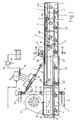
- FIG. 1 shows that one of the components of a spray boom positioned, with the possibility of reducing the overall dimensions, at the side of the means of transport, consists of at least two tubular sections 1 and 1' of any material suitable for the purpose, which when seen in section as in Figure 3 have a profile in the shape of an inverted U, with lower, longitudinal and median channels 2, 2' in each of which the pipes 3 and 3' are housed longitudinally with the nozzles 4, 4' which spray the treatment liquid downwards.
- Figures 1 and 3 show that the pipe 3 is fixed in the channel 2 of the fixed section 1, while the pipe 3' is positioned in such a way that it can be lowered and raised in the channel 2' of the movable section 1', the latter channel having a height or depth greater than that of the channel 1 of the fixed section, so that, when the movable section 1' is moved longitudinally, the pipe 3' with the nozzles 4' is in the raised position, as illustrated in broken lines, in such a way that it is positioned above the channel 2 carrying the fixed pipe 3, while when the section 1' is fully extended the corresponding pipe 3' can be lowered and aligned so that it is coplanar with the pipe 3, as illustrated in Figure 1 in solid lines.
- the pipe is, for example, connected to levers 5 pivoted at 6 to the section 1', thus forming an articulated parallelogram, at least one of these levers being provided with an extension 105 which projects beyond the pivot 6, for connection to an actuator 7 fixed inside the section 1', which raises or lowers the pipe 3' through the necessary distance.
- Rotary distributors of a known type D1, D2 can be provided on the end of the fixed section 1 which is on the left-hand side of Figure 1 , to control the tension of the supply tubes of the pipe 3' and of the cylinder 7, the whole arrangement being easily understood and implemented by persons skilled in the art.
- the movable section 1' slides longitudinally in the fixed section 1 with the interposition of pads 20 and 20' of suitable material, the pads 20 being fixed inside the right-hand end of section 1, while the pads 20' are fixed outside the left-hand end of section 1'.
- the longitudinal movement of extension and retraction of the section 1' can be obtained, for example, by means of a chain or rack 8 fixed in a median and upper longitudinal housing 301' of the section 1', which also helps to stiffen this section, this chain or rack engaging with the pinion 9 of a motor or geared motor 10 of any suitable type, flange-fitted to a support 11 fixed on the farthest projecting end of the section 1.
- a chain or rack 8 fixed in a median and upper longitudinal housing 301' of the section 1', which also helps to stiffen this section, this chain or rack engaging with the pinion 9 of a motor or geared motor 10 of any suitable type, flange-fitted to a support 11 fixed on the farthest projecting end of the section 1.
- the section 1 is supported with the possibility of oscillation for pitching movements on a horizontal and transverse shaft 12 carried by a structure 13 which in turn is supported, with the possibility of slewing on a vertical shaft 14, by a support structure 15.
- Actuators are provided for moving the telescopic boom about the aforesaid shafts 12 and 14.
- each of these actuators can advantageously consist of a pair of cylinders 16, 16' with opposing rods, fixed together by their bases, which are controlled through a distribution box 17 to position the boom in the operating position or in the rest position, and which are such that, when the said boom is in the extended horizontal operating position, the said cylinders can allow the boom to make additional upward or downward pitching movements, or forward or backward slewing movements.
- At least one safety valve 19 is connected by a branch to the opposing pressure chambers of the cylinders 16 and 16', through one-way valves 18 for example, this safety valve coming into operation automatically and discharging the oil from either one of the two cylinders whenever the boom in question is touched at any point by an obstacle which tends to make it pitch or slew.
- the safety valve 19 is provided with an outlet 119 of any type, including the electrical type, which in case of intervention initiates safety procedures, such as the automatic stop of the spraying machine, including the spraying of the liquid by the nozzles 4, 4', in such a way as to prevent dangerous concentrations of the treatment liquid on the ground.
- the spray boom according to the invention is also highly suitable for executing spraying treatments of the "air-assisted" type, since it can use the tubular sections 1, 1' as natural channels for guiding pressurized air.
- the free ends 101 and 101' of the sections 1 and 1' are closed, the end of the channel 2' of the movable section 1' is closed in the part 201' which reaches the channel 2 of the fixed section 1, and an annular sealing means is provided at the position of the pads 20' and also bears on the lower edge of the said wall 201', in such a way as to provide an annular connection with the best possible seal between the inverted-U chambers of section 1 and section 1'.
- a pressurized air generator 22 having suitable characteristics for the purpose, driven by a motor of any suitable type, which introduces air at correct values of pressure and flow rate into the inner chambers of the sections 1, 1'.
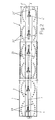
- the figures, and in particular Figure 2 show how at least the end walls of the sections 1, 1' are provided, in the area of the nozzles 4, 4' and around the nozzles, with rings, of ellipsoid shape for example, of downward facing holes 23, 23', through which the pressurized air produced by the generator 22 flows out, in such a way as to provide an effective curtain to prevent drift due to wind, which is also effective against winds blowing orthogonally with respect to the direction of travel of the boom.
- the holes 23, 23' are interrupted in the area of the channels 2, 2', but it should be understood that, in a variant embodiment, they can also be present in the upper walls of these channels, in such a way as to form true rings of holes, completely surrounding each nozzle.
- the sum of the cross sections of all the rings of holes 23, 23' provided in the sections 1, 1' of a boom according to the invention is markedly lower than that of the holes provided over the whole length of the flexible sleeves of known systems, and therefore the invention permits the use of a generator 22 of smaller capacity.
- the sum of the cross sections of all the holes 23, 23' in the telescopic boom 1, 1' is equal to or preferably less than the area of the aperture 21, in such a way that the air produced by the generator 22 can reach even the holes which are most remote from the said generator with correct values of pressure and flow rate.
Landscapes
- Life Sciences & Earth Sciences (AREA)
- Environmental Sciences (AREA)
- Insects & Arthropods (AREA)
- Pest Control & Pesticides (AREA)
- Wood Science & Technology (AREA)
- Zoology (AREA)
- Engineering & Computer Science (AREA)
- Catching Or Destruction (AREA)
- Jib Cranes (AREA)
- Forklifts And Lifting Vehicles (AREA)
- Sawing (AREA)
- Pens And Brushes (AREA)
- Holders For Apparel And Elements Relating To Apparel (AREA)
Claims (19)
- Rampe de pulvérisation de principes actifs en agriculture du type transporté, tracté ou à auto propulsion et comprenant des bras ou sections (1, 1') ayant un profil approprié en canal, en un matériau approprié résistant au mouvements de flexion et de torsion, pouvant coulisser télescopiquement l'un dans l'autre sous l'action de moyens appropriés de guidage et d'entraînement de façon à former des structures légères qui ne sont pas soumises à des couples de torsion des bras dans les étapes de déploiement et de retrait et qui ont des dimensions globales limitées en la position rétractée, les conduits (3, 3') étant avec les buses (4, 4') de pulvérisation fixés d'une façon convenable auxdites sections, caractérisée en ce que les sections (1, 1') tubulaires dont la rampe est constituée sont fermées pour être utilisées en tant que canaux véhiculant de l'air comprimé, la rampe convenant pour effectuer des traitements de pulvérisation du type à « assistance pneumatique ».
- Rampe suivant la revendication 1, dans laquelle les sections (1, 1') en canaux qui la forment sont faites d'une section tubulaire.
- Rampe suivant la revendication 2, dans laquelle les sections (1, 1') tubulaires qui la forment ont un profil sous la forme d'un U inversé et les conduits (3, 3') sont avec les buses (4, 4') positionnés dans les canaux (2, 2') longitudinaux sur le côté inférieur desdites sections.
- Rampe suivant la revendication 3, dans laquelle la section (1) fixe a le conduit (3) correspondant ayant les buses (4) fixées longitudinalement dans son canal (2), tandis que le conduit (3') correspondant ayant les buses (4') est logé dans le canaux (2') de la section (1') mobile de façon à ce qu'il puisse être abaissé et soulevé dans ce canal (2), qui a une hauteur ou une profondeur plus grande que celle du canal de la section (1) fixe de sorte que, lorsque la section (1') mobile est déplacée longitudinalement, le conduit (3') correspondant ayant les buses (4') est dans la position soulevée de telle façon qu'il est positionné au dessus du canal (2) ayant le conduit (3) fixe, tandis que, lorsque la section (1') mobile est déployée complètement, le conduit (3') correspondant peut être rabaissé et aligné de manière à être coplanaire avec celui (3) de la section (1) fixe.
- Rampe suivant la revendication 4, dans laquelle le conduit (3') ayant les buses (4') de la section (1') mobile est relié à des leviers (5) articulés sur ladite section (1') pour former un parallélogramme articulé et au moins l'un de ces leviers est muni d'un prolongement (105) qui va au-delà du pivot en vu d'être relié à un actionneur (7) fixé à l'intérieur de cette section (1') et soulevant ou abaissant le conduit (3').
- Rampe suivant l'une quelconque ou plusieurs des revendications précédentes, dans laquelle des distributeurs (D1, D2) tournants peuvent être prévus sur l'extrémité libre de la section (1) fixe pour commander les tubes d'alimentation du conduit (3') et du cylindre (7) de l'actionneur monté dans la section (1') mobile.
- Rampe suivant l'une quelconque ou plusieurs des revendications précédentes, dans laquelle la section (1') mobile coulisse longitudinalement dans la section (1) fixe avec l'interposition de tampons (20, 20') en un matériau approprié, certains d'entre eux étant fixés à l'intérieur de l'extrémité de la section fixe qui interagit avec la section (1') mobile, tandis que d'autres sont fixés à l'extérieur de l'extrémité de la section (1') mobile qui coulisse dans la section fixe.
- Rampe suivant l'une quelconque ou plusieurs des revendications précédentes, dans laquelle un système approprié de servocommande est prévu pour faire que la section (1') mobile coulisse longitudinalement dans la section fixe qui forme la rampe pour, amener cette dernière dans l'état de déploiement maximum, en d'autres termes dans l'état opératoire, ou dans l'état de retrait maximum, en d'autres termes dans l'état de repos.
- Rampe suivant la revendication 8, dans laquelle la section (1') mobile est munie d'un chambrage (301') longitudinal placé par exemple en une position médiane, dans lequel est fixée une chaîne ou une crémaillère (8) qui engrène dans un pignon (9) d'un moteur ou d'un motoréducteur (10) d'un type approprié, bridé sur un support (11) fixé sur l'extrémité faisant saillie le plus loin de la section (1) fixe.
- Rampe suivant l'une quelconque ou plusieurs des revendications précédentes, dans laquelle la section (1) fixe est supportée avec possibilité d'oscillation sur un arbre (12) horizontal et transversal pour les mouvements de tangage, et cet arbre est porté par une structure (13) qui est supportée à son tour par une structure (15) de support avec la possibilité de pivotement sur un arbre (14) vertical de sorte que la rampe peut être positionnée, dans la position de fonctionnement, transversalement à la direction d'avancement sur le sol ou, dans la position de repos, parallèlement à la direction de l'avancement, des actionneurs appropriés étant prévus pour produire les mouvements de tangage et de pivotement indépendamment.
- Rampe suivant la revendication 10, dans laquelle chacun des actionneurs pour déplacer la rampe consiste en une paire de vérins (16, 16') à tiges opposées, fixés ensemble par leur base, qui sont commandés par une boîte (17) de distribution et qui sont tels que, lorsque la rampe est dans la position de fonctionnement horizontale déployée, les vérins peuvent permettre à la rampe de faire des mouvements supplémentaires de tangage vers le haut ou vers le bas, ou des mouvements oscillants vertical vers l'avant ou vers l'arrière au moins une soupape (19) de sécurité communiquant par une branche avec les chambres de pression opposées des vérins (16, 16') par des vannes (18) à une voie par exemple, cette soupape de sécurité venant en fonctionnement automatiquement et guidant l'huile de l'un des deux vérins si la rampe en question est touchée en un point quelconque par un obstacle qui tend à la faire tanguer ou pivoter.
- Rampe suivant la revendication 11, dans laquelle la soupape (19) de sécurité est munie d'une sortie (119) d'un type quelconque, y compris du type électrique, qui, dans le cas d'une intervention, lance des procédures de sécurité, telles que l'arrêt automatique de la machine de pulvérisation.
- Rampe suivant la revendication 1, dans laquelle les extrémités (101) et (101') libres des sections (1, 1'), dont elle est constituée, sont fermées et l'extrémité du canal (2') de la section (1') mobile est fermée dans la partie (201') qui atteint le canal (2) de la section (1) fixe, tandis que dans la zone des tampons (20') de la section (1') mobile, un moyen annulaire d'étanchéité est prévu et porte aussi sur le bord inférieur de la paroi (201') de façon à ménager une liaison rendue étanche entre les chambres intérieures en U inversé des dites sections (1, 1').
- Rampe suivant la revendication 13, dans laquelle sur l'extrémité libre de la section (1) fixe, il y a une ouverture (21) sur laquelle il est possible de brider directement ou avec l'interposition d'un manchon souple, un générateur (22) d'air comprimé entraîné par un moteur de tout type convenable, qui introduit de l'air à des valeurs correctes de pression et de débit dans les chambres intérieures des sections (1, 1') de la rampe.
- Rampe suivant la revendication 14, dans laquelle au moins les parois d'extrémité des sections (1, 1') sont munies, dans la zone des buses (4, 4') et autour des buses, d'anneaux de trous (23, 23') faisant face vers le bas et par lesquels sort l'air comprimé produit par le générateur (22) de façon à ménager une barrière de protection à l'encontre d'une dérive dû au vent, qui est efficace aussi à l'encontre des courants d'air soufflant orthogonalement par rapport à la direction de déplacement de la rampe.
- Rampe suivant la revendication 15, dans laquelle les anneaux de trous (23, 23') sont de forme ellipsoïde en vue en plan et les buses (4, 4') sont disposées au centre de ces anneaux.
- Rampe suivant la revendication 15, dans laquelle les anneaux de trous (23, 23') sont interrompus dans la zone des canaux (2, 2') dans les côtés inférieurs des sections (1, 1') dont est constituée la rampe.
- Rampe suivant la revendication 15, dans laquelle les anneaux de trous (23, 23') sont présents aussi dans les parois supérieures des canaux (2, 2'), de façon à former des anneaux de trous, qui entourent chaque buse.
- Rampe suivant la revendication 15, dans laquelle la somme des sections transversales de tous les trous (23, 23') inférieurs dans les sections (1, 1') télescopique dont est constitué la rampe est égale ou de préférence inférieure à la superficie de l'ouverture (21) d'entrée reliée au générateur (22) de sorte que l'air produit par ce générateur peut atteindre même les trous (23, 23') les plus reculés en ayant des valeurs correctes de la pression et du débit.
Applications Claiming Priority (2)
| Application Number | Priority Date | Filing Date | Title |
|---|---|---|---|
| ITBO20030220 | 2003-04-14 | ||
| IT000220A ITBO20030220A1 (it) | 2003-04-14 | 2003-04-14 | Barra di irrorazione a bracci telescopici |
Publications (2)
| Publication Number | Publication Date |
|---|---|
| EP1468604A1 EP1468604A1 (fr) | 2004-10-20 |
| EP1468604B1 true EP1468604B1 (fr) | 2009-02-11 |
Family
ID=32894145
Family Applications (1)
| Application Number | Title | Priority Date | Filing Date |
|---|---|---|---|
| EP04008725A Expired - Lifetime EP1468604B1 (fr) | 2003-04-14 | 2004-04-13 | Rampe de pulvérisation à bras téléscopique |
Country Status (5)
| Country | Link |
|---|---|
| EP (1) | EP1468604B1 (fr) |
| AT (1) | ATE422293T1 (fr) |
| DE (1) | DE602004019354D1 (fr) |
| DK (1) | DK1468604T3 (fr) |
| IT (1) | ITBO20030220A1 (fr) |
Cited By (3)
| Publication number | Priority date | Publication date | Assignee | Title |
|---|---|---|---|---|
| WO2024241153A1 (fr) * | 2023-05-24 | 2024-11-28 | Ecorobotix Sa | Unité télescopique agricole pour le traitement de plantes |
| WO2025093083A1 (fr) * | 2023-10-31 | 2025-05-08 | Kornbrennerei Icking e.K. | Dispositifs de distribution d'au moins un milieu liquide ; procédé de distribution d'au moins un milieu liquide |
| EP4721562A1 (fr) * | 2024-10-04 | 2026-04-08 | EcoRobotix SA | Unité télescopique agricole pour le traitement de plantes |
Families Citing this family (10)
| Publication number | Priority date | Publication date | Assignee | Title |
|---|---|---|---|---|
| DE102007001915A1 (de) * | 2006-01-26 | 2007-08-09 | Lemken Gmbh & Co. Kg | Spritzgestänge für Feldspritzen |
| WO2009046723A1 (fr) * | 2007-09-19 | 2009-04-16 | Albert Hedegaard | Rampe de pulvérisateur pour dispositif de pulvérisation agricole |
| ITCR20100009A1 (it) * | 2010-03-18 | 2011-09-19 | Mario Dalseno | Barra irroratrice |
| FR2963894B1 (fr) | 2010-08-17 | 2013-04-05 | Exel Ind | Systeme de production d'au moins un courant d'air de section transversale allongee |
| FR3075567B1 (fr) | 2017-12-22 | 2021-05-28 | Institut National De Recherche En Sciences Et Tech Pour Lenvironnement Et Lagriculture | Systeme et procede de pulverisation de produit, notamment de produit phytosanitaire |
| CN108244084B (zh) * | 2018-03-23 | 2023-06-20 | 南京林业大学 | 一种林木喷雾机仿形机臂及其仿形喷雾的方法 |
| CN109156463A (zh) * | 2018-11-13 | 2019-01-08 | 西北农林科技大学 | 一种自动化喷药机构的控制系统及其控制方法 |
| CN111155612B (zh) * | 2020-03-10 | 2025-02-07 | 厦门科牧智能技术有限公司 | 一种用于智能马桶盖的喷洗组件及该喷洗组件装配方法 |
| CN114365734B (zh) * | 2022-03-08 | 2023-02-10 | 王静 | 一种果树种植用病虫防治喷药装置 |
| CN114671500B (zh) * | 2022-04-26 | 2023-07-25 | 四川水利职业技术学院 | 一种水生态治理设备 |
Family Cites Families (5)
| Publication number | Priority date | Publication date | Assignee | Title |
|---|---|---|---|---|
| GB557068A (en) * | 1942-03-30 | 1943-11-03 | Pest Control Ltd | A vehicle for spraying agents for combatting pests and for other purposes |
| DK325478A (da) * | 1977-11-15 | 1979-05-16 | Agram | Styreanordning til brug ved spredning eller forstoevning af behandlingsprodukter og lignende materialer |
| FR2541912B1 (fr) | 1983-03-03 | 1988-08-19 | Seguip | Perfectionnements aux rampes de pulverisation agricole |
| DK213389A (da) * | 1989-05-02 | 1990-11-03 | Gunnar Arenhoff Eriksen | Mobilt vandingsapparat med ud- og indfoldelig spredebom |
| EP1148780A1 (fr) * | 1999-01-05 | 2001-10-31 | Albert Hedegard | Rampe de pulverisateur |
-
2003
- 2003-04-14 IT IT000220A patent/ITBO20030220A1/it unknown
-
2004
- 2004-04-13 DK DK04008725T patent/DK1468604T3/da active
- 2004-04-13 EP EP04008725A patent/EP1468604B1/fr not_active Expired - Lifetime
- 2004-04-13 AT AT04008725T patent/ATE422293T1/de not_active IP Right Cessation
- 2004-04-13 DE DE602004019354T patent/DE602004019354D1/de not_active Expired - Lifetime
Cited By (3)
| Publication number | Priority date | Publication date | Assignee | Title |
|---|---|---|---|---|
| WO2024241153A1 (fr) * | 2023-05-24 | 2024-11-28 | Ecorobotix Sa | Unité télescopique agricole pour le traitement de plantes |
| WO2025093083A1 (fr) * | 2023-10-31 | 2025-05-08 | Kornbrennerei Icking e.K. | Dispositifs de distribution d'au moins un milieu liquide ; procédé de distribution d'au moins un milieu liquide |
| EP4721562A1 (fr) * | 2024-10-04 | 2026-04-08 | EcoRobotix SA | Unité télescopique agricole pour le traitement de plantes |
Also Published As
| Publication number | Publication date |
|---|---|
| EP1468604A1 (fr) | 2004-10-20 |
| ATE422293T1 (de) | 2009-02-15 |
| DK1468604T3 (da) | 2009-05-18 |
| DE602004019354D1 (de) | 2009-03-26 |
| ITBO20030220A1 (it) | 2004-10-15 |
Similar Documents
| Publication | Publication Date | Title |
|---|---|---|
| EP1468604A1 (fr) | Rampe de pulvérisation à bras téléscopique | |
| CN204014860U (zh) | 自走式喷药机的喷药机构 | |
| US3352493A (en) | Self propelled irrigator | |
| CN106234341A (zh) | 一种农作物精准喷洒系统 | |
| US20110147487A1 (en) | Horizontally pivotable agricultural sprayer with vertically pivotable segments | |
| CN109042590B (zh) | 一种农作物自动化喷洒系统 | |
| CN102696572A (zh) | 一种自走式喷杆喷雾机 | |
| BR102018016434B1 (pt) | Sistema de pulverizador, e, máquina de trabalho agrícola | |
| US20240417231A1 (en) | Aerial work platform | |
| RU163954U1 (ru) | Широкозахватная дождевальная машина | |
| CN209073073U (zh) | 一种温室三维喷淋机 | |
| CN111109233A (zh) | 一种智能控制式果园风送喷雾机的扩缩门喷雾系统 | |
| US11465164B1 (en) | Retractable spray shield for agricultural use | |
| EP3488687A1 (fr) | Appareil d'arrosage et ensemble | |
| CN108246552A (zh) | 一种电驱动式多方位洒水喷药执行装置 | |
| US3599664A (en) | Self-propelled irrigating apparatus | |
| ITPD20120219A1 (it) | Macchina irroratrice a tunnel perfezionata per distribuire prodotti fitosanitari su colture arboree | |
| CN215380324U (zh) | 一种适用于日光温室大棚的地面轨道式移动微喷灌机组 | |
| SU1588295A1 (ru) | Система мостового земледели | |
| RU2351119C1 (ru) | Подвижное ирригационное устройство | |
| KR20110091277A (ko) | 살수 장치 | |
| CN206061949U (zh) | 一种农作物精准喷洒系统 | |
| JP2016220653A (ja) | 除草剤散布車 | |
| US12453341B1 (en) | Retractable spray shield for agricultural use | |
| CN114467896B (zh) | 一种植保用药物喷洒机构 |
Legal Events
| Date | Code | Title | Description |
|---|---|---|---|
| PUAI | Public reference made under article 153(3) epc to a published international application that has entered the european phase |
Free format text: ORIGINAL CODE: 0009012 |
|
| AK | Designated contracting states |
Kind code of ref document: A1 Designated state(s): AT BE BG CH CY CZ DE DK EE ES FI FR GB GR HU IE IT LI LU MC NL PL PT RO SE SI SK TR |
|
| AX | Request for extension of the european patent |
Extension state: AL HR LT LV MK |
|
| 17P | Request for examination filed |
Effective date: 20050401 |
|
| AKX | Designation fees paid |
Designated state(s): AT BE BG CH CY CZ DE DK EE ES FI FR GB GR HU IE IT LI LU MC NL PL PT RO SE SI SK TR |
|
| AXX | Extension fees paid |
Extension state: LV Payment date: 20050401 Extension state: HR Payment date: 20050401 Extension state: MK Payment date: 20050401 Extension state: LT Payment date: 20050401 Extension state: AL Payment date: 20050401 |
|
| RAP1 | Party data changed (applicant data changed or rights of an application transferred) |
Owner name: BARGAM S.P.A. |
|
| 17Q | First examination report despatched |
Effective date: 20070601 |
|
| GRAP | Despatch of communication of intention to grant a patent |
Free format text: ORIGINAL CODE: EPIDOSNIGR1 |
|
| GRAS | Grant fee paid |
Free format text: ORIGINAL CODE: EPIDOSNIGR3 |
|
| GRAA | (expected) grant |
Free format text: ORIGINAL CODE: 0009210 |
|
| AK | Designated contracting states |
Kind code of ref document: B1 Designated state(s): AT BE BG CH CY CZ DE DK EE ES FI FR GB GR HU IE IT LI LU MC NL PL PT RO SE SI SK TR |
|
| AX | Request for extension of the european patent |
Extension state: AL HR LT LV MK |
|
| REG | Reference to a national code |
Ref country code: GB Ref legal event code: FG4D |
|
| REG | Reference to a national code |
Ref country code: CH Ref legal event code: EP |
|
| REG | Reference to a national code |
Ref country code: IE Ref legal event code: FG4D |
|
| REF | Corresponds to: |
Ref document number: 602004019354 Country of ref document: DE Date of ref document: 20090326 Kind code of ref document: P |
|
| REG | Reference to a national code |
Ref country code: DK Ref legal event code: T3 |
|
| LTIE | Lt: invalidation of european patent or patent extension |
Effective date: 20090211 |
|
| PG25 | Lapsed in a contracting state [announced via postgrant information from national office to epo] |
Ref country code: ES Free format text: LAPSE BECAUSE OF FAILURE TO SUBMIT A TRANSLATION OF THE DESCRIPTION OR TO PAY THE FEE WITHIN THE PRESCRIBED TIME-LIMIT Effective date: 20090522 Ref country code: FI Free format text: LAPSE BECAUSE OF FAILURE TO SUBMIT A TRANSLATION OF THE DESCRIPTION OR TO PAY THE FEE WITHIN THE PRESCRIBED TIME-LIMIT Effective date: 20090211 Ref country code: SI Free format text: LAPSE BECAUSE OF FAILURE TO SUBMIT A TRANSLATION OF THE DESCRIPTION OR TO PAY THE FEE WITHIN THE PRESCRIBED TIME-LIMIT Effective date: 20090211 Ref country code: NL Free format text: LAPSE BECAUSE OF FAILURE TO SUBMIT A TRANSLATION OF THE DESCRIPTION OR TO PAY THE FEE WITHIN THE PRESCRIBED TIME-LIMIT Effective date: 20090211 |
|
| NLV1 | Nl: lapsed or annulled due to failure to fulfill the requirements of art. 29p and 29m of the patents act | ||
| PG25 | Lapsed in a contracting state [announced via postgrant information from national office to epo] |
Ref country code: SE Free format text: LAPSE BECAUSE OF FAILURE TO SUBMIT A TRANSLATION OF THE DESCRIPTION OR TO PAY THE FEE WITHIN THE PRESCRIBED TIME-LIMIT Effective date: 20090511 Ref country code: AT Free format text: LAPSE BECAUSE OF FAILURE TO SUBMIT A TRANSLATION OF THE DESCRIPTION OR TO PAY THE FEE WITHIN THE PRESCRIBED TIME-LIMIT Effective date: 20090211 Ref country code: PL Free format text: LAPSE BECAUSE OF FAILURE TO SUBMIT A TRANSLATION OF THE DESCRIPTION OR TO PAY THE FEE WITHIN THE PRESCRIBED TIME-LIMIT Effective date: 20090211 |
|
| PG25 | Lapsed in a contracting state [announced via postgrant information from national office to epo] |
Ref country code: BE Free format text: LAPSE BECAUSE OF FAILURE TO SUBMIT A TRANSLATION OF THE DESCRIPTION OR TO PAY THE FEE WITHIN THE PRESCRIBED TIME-LIMIT Effective date: 20090211 |
|
| PG25 | Lapsed in a contracting state [announced via postgrant information from national office to epo] |
Ref country code: CZ Free format text: LAPSE BECAUSE OF FAILURE TO SUBMIT A TRANSLATION OF THE DESCRIPTION OR TO PAY THE FEE WITHIN THE PRESCRIBED TIME-LIMIT Effective date: 20090211 Ref country code: PT Free format text: LAPSE BECAUSE OF FAILURE TO SUBMIT A TRANSLATION OF THE DESCRIPTION OR TO PAY THE FEE WITHIN THE PRESCRIBED TIME-LIMIT Effective date: 20090713 Ref country code: EE Free format text: LAPSE BECAUSE OF FAILURE TO SUBMIT A TRANSLATION OF THE DESCRIPTION OR TO PAY THE FEE WITHIN THE PRESCRIBED TIME-LIMIT Effective date: 20090211 |
|
| PG25 | Lapsed in a contracting state [announced via postgrant information from national office to epo] |
Ref country code: SK Free format text: LAPSE BECAUSE OF FAILURE TO SUBMIT A TRANSLATION OF THE DESCRIPTION OR TO PAY THE FEE WITHIN THE PRESCRIBED TIME-LIMIT Effective date: 20090211 Ref country code: RO Free format text: LAPSE BECAUSE OF FAILURE TO SUBMIT A TRANSLATION OF THE DESCRIPTION OR TO PAY THE FEE WITHIN THE PRESCRIBED TIME-LIMIT Effective date: 20090211 |
|
| REG | Reference to a national code |
Ref country code: CH Ref legal event code: PL |
|
| PLBE | No opposition filed within time limit |
Free format text: ORIGINAL CODE: 0009261 |
|
| STAA | Information on the status of an ep patent application or granted ep patent |
Free format text: STATUS: NO OPPOSITION FILED WITHIN TIME LIMIT |
|
| 26N | No opposition filed |
Effective date: 20091112 |
|
| GBPC | Gb: european patent ceased through non-payment of renewal fee |
Effective date: 20090511 |
|
| PG25 | Lapsed in a contracting state [announced via postgrant information from national office to epo] |
Ref country code: LI Free format text: LAPSE BECAUSE OF NON-PAYMENT OF DUE FEES Effective date: 20090430 Ref country code: CH Free format text: LAPSE BECAUSE OF NON-PAYMENT OF DUE FEES Effective date: 20090430 Ref country code: BG Free format text: LAPSE BECAUSE OF FAILURE TO SUBMIT A TRANSLATION OF THE DESCRIPTION OR TO PAY THE FEE WITHIN THE PRESCRIBED TIME-LIMIT Effective date: 20090511 |
|
| PG25 | Lapsed in a contracting state [announced via postgrant information from national office to epo] |
Ref country code: MC Free format text: LAPSE BECAUSE OF NON-PAYMENT OF DUE FEES Effective date: 20090430 Ref country code: IE Free format text: LAPSE BECAUSE OF NON-PAYMENT OF DUE FEES Effective date: 20090413 |
|
| PG25 | Lapsed in a contracting state [announced via postgrant information from national office to epo] |
Ref country code: GB Free format text: LAPSE BECAUSE OF NON-PAYMENT OF DUE FEES Effective date: 20090511 |
|
| PG25 | Lapsed in a contracting state [announced via postgrant information from national office to epo] |
Ref country code: GR Free format text: LAPSE BECAUSE OF FAILURE TO SUBMIT A TRANSLATION OF THE DESCRIPTION OR TO PAY THE FEE WITHIN THE PRESCRIBED TIME-LIMIT Effective date: 20090512 |
|
| PG25 | Lapsed in a contracting state [announced via postgrant information from national office to epo] |
Ref country code: LU Free format text: LAPSE BECAUSE OF NON-PAYMENT OF DUE FEES Effective date: 20090413 |
|
| PG25 | Lapsed in a contracting state [announced via postgrant information from national office to epo] |
Ref country code: HU Free format text: LAPSE BECAUSE OF FAILURE TO SUBMIT A TRANSLATION OF THE DESCRIPTION OR TO PAY THE FEE WITHIN THE PRESCRIBED TIME-LIMIT Effective date: 20090812 |
|
| PG25 | Lapsed in a contracting state [announced via postgrant information from national office to epo] |
Ref country code: TR Free format text: LAPSE BECAUSE OF FAILURE TO SUBMIT A TRANSLATION OF THE DESCRIPTION OR TO PAY THE FEE WITHIN THE PRESCRIBED TIME-LIMIT Effective date: 20090211 |
|
| PG25 | Lapsed in a contracting state [announced via postgrant information from national office to epo] |
Ref country code: CY Free format text: LAPSE BECAUSE OF FAILURE TO SUBMIT A TRANSLATION OF THE DESCRIPTION OR TO PAY THE FEE WITHIN THE PRESCRIBED TIME-LIMIT Effective date: 20090211 |
|
| REG | Reference to a national code |
Ref country code: DE Ref legal event code: R082 Ref document number: 602004019354 Country of ref document: DE Representative=s name: WSL PATENTANWAELTE PARTNERSCHAFT MBB, DE |
|
| REG | Reference to a national code |
Ref country code: DE Ref legal event code: R082 Ref document number: 602004019354 Country of ref document: DE Representative=s name: WSL PATENTANWAELTE PARTNERSCHAFT MBB, DE Effective date: 20150325 Ref country code: DE Ref legal event code: R081 Ref document number: 602004019354 Country of ref document: DE Owner name: BGROUP S.P.A., IT Free format text: FORMER OWNER: BARGAM S.P.A., IMOLA, IT Effective date: 20150325 |
|
| REG | Reference to a national code |
Ref country code: FR Ref legal event code: CD Owner name: BGROUP S.P.A. Effective date: 20150608 |
|
| PGFP | Annual fee paid to national office [announced via postgrant information from national office to epo] |
Ref country code: DK Payment date: 20150428 Year of fee payment: 12 Ref country code: DE Payment date: 20150422 Year of fee payment: 12 |
|
| REG | Reference to a national code |
Ref country code: FR Ref legal event code: PLFP Year of fee payment: 13 |
|
| REG | Reference to a national code |
Ref country code: DE Ref legal event code: R119 Ref document number: 602004019354 Country of ref document: DE |
|
| REG | Reference to a national code |
Ref country code: DK Ref legal event code: EBP Effective date: 20160430 |
|
| PG25 | Lapsed in a contracting state [announced via postgrant information from national office to epo] |
Ref country code: DE Free format text: LAPSE BECAUSE OF NON-PAYMENT OF DUE FEES Effective date: 20161101 |
|
| REG | Reference to a national code |
Ref country code: FR Ref legal event code: PLFP Year of fee payment: 14 |
|
| PG25 | Lapsed in a contracting state [announced via postgrant information from national office to epo] |
Ref country code: DK Free format text: LAPSE BECAUSE OF NON-PAYMENT OF DUE FEES Effective date: 20160430 |
|
| PGFP | Annual fee paid to national office [announced via postgrant information from national office to epo] |
Ref country code: FR Payment date: 20170420 Year of fee payment: 14 |
|
| PG25 | Lapsed in a contracting state [announced via postgrant information from national office to epo] |
Ref country code: FR Free format text: LAPSE BECAUSE OF NON-PAYMENT OF DUE FEES Effective date: 20180430 |
|
| PGFP | Annual fee paid to national office [announced via postgrant information from national office to epo] |
Ref country code: IT Payment date: 20230428 Year of fee payment: 20 |