EP1468650B1 - System und Methode zur Röntgencomputertomographie mit Korrektur der Strahlaufhärtung - Google Patents
System und Methode zur Röntgencomputertomographie mit Korrektur der Strahlaufhärtung Download PDFInfo
- Publication number
- EP1468650B1 EP1468650B1 EP04252253A EP04252253A EP1468650B1 EP 1468650 B1 EP1468650 B1 EP 1468650B1 EP 04252253 A EP04252253 A EP 04252253A EP 04252253 A EP04252253 A EP 04252253A EP 1468650 B1 EP1468650 B1 EP 1468650B1
- Authority
- EP
- European Patent Office
- Prior art keywords
- projection information
- correction coefficient
- ray
- phantom
- correction
- Prior art date
- Legal status (The legal status is an assumption and is not a legal conclusion. Google has not performed a legal analysis and makes no representation as to the accuracy of the status listed.)
- Expired - Lifetime
Links
- 238000000034 method Methods 0.000 title claims description 15
- 238000001514 detection method Methods 0.000 claims description 32
- 230000000694 effects Effects 0.000 claims description 23
- 238000012805 post-processing Methods 0.000 claims description 8
- 230000002194 synthesizing effect Effects 0.000 claims 1
- 238000002591 computed tomography Methods 0.000 description 18
- 238000012545 processing Methods 0.000 description 17
- 238000010586 diagram Methods 0.000 description 6
- 230000008859 change Effects 0.000 description 4
- 238000009499 grossing Methods 0.000 description 3
- 230000004048 modification Effects 0.000 description 3
- 238000012986 modification Methods 0.000 description 3
- MARUHZGHZWCEQU-UHFFFAOYSA-N 5-phenyl-2h-tetrazole Chemical compound C1=CC=CC=C1C1=NNN=N1 MARUHZGHZWCEQU-UHFFFAOYSA-N 0.000 description 2
- 230000015556 catabolic process Effects 0.000 description 2
- 238000006731 degradation reaction Methods 0.000 description 2
- 238000007781 pre-processing Methods 0.000 description 2
- 230000008569 process Effects 0.000 description 2
- 230000035945 sensitivity Effects 0.000 description 2
- 239000004743 Polypropylene Substances 0.000 description 1
- 238000010521 absorption reaction Methods 0.000 description 1
- 230000007547 defect Effects 0.000 description 1
- 238000012886 linear function Methods 0.000 description 1
- -1 polypropylene Polymers 0.000 description 1
- 229920001155 polypropylene Polymers 0.000 description 1
- 239000004065 semiconductor Substances 0.000 description 1
- 229910052724 xenon Inorganic materials 0.000 description 1
- FHNFHKCVQCLJFQ-UHFFFAOYSA-N xenon atom Chemical compound [Xe] FHNFHKCVQCLJFQ-UHFFFAOYSA-N 0.000 description 1
Images







Classifications
-
- A—HUMAN NECESSITIES
- A61—MEDICAL OR VETERINARY SCIENCE; HYGIENE
- A61B—DIAGNOSIS; SURGERY; IDENTIFICATION
- A61B6/00—Apparatus or devices for radiation diagnosis; Apparatus or devices for radiation diagnosis combined with radiation therapy equipment
- A61B6/58—Testing, adjusting or calibrating thereof
- A61B6/582—Calibration
- A61B6/583—Calibration using calibration phantoms
-
- A—HUMAN NECESSITIES
- A61—MEDICAL OR VETERINARY SCIENCE; HYGIENE
- A61G—TRANSPORT, PERSONAL CONVEYANCES, OR ACCOMMODATION SPECIALLY ADAPTED FOR PATIENTS OR DISABLED PERSONS; OPERATING TABLES OR CHAIRS; CHAIRS FOR DENTISTRY; FUNERAL DEVICES
- A61G9/00—Bed-pans, urinals or other sanitary devices for bed-ridden persons; Cleaning devices therefor, e.g. combined with toilet-urinals
- A61G9/003—Bed-pans
-
- A—HUMAN NECESSITIES
- A61—MEDICAL OR VETERINARY SCIENCE; HYGIENE
- A61B—DIAGNOSIS; SURGERY; IDENTIFICATION
- A61B6/00—Apparatus or devices for radiation diagnosis; Apparatus or devices for radiation diagnosis combined with radiation therapy equipment
- A61B6/02—Arrangements for diagnosis sequentially in different planes; Stereoscopic radiation diagnosis
- A61B6/03—Computed tomography [CT]
- A61B6/032—Transmission computed tomography [CT]
-
- A—HUMAN NECESSITIES
- A61—MEDICAL OR VETERINARY SCIENCE; HYGIENE
- A61B—DIAGNOSIS; SURGERY; IDENTIFICATION
- A61B6/00—Apparatus or devices for radiation diagnosis; Apparatus or devices for radiation diagnosis combined with radiation therapy equipment
- A61B6/48—Diagnostic techniques
- A61B6/488—Diagnostic techniques involving pre-scan acquisition
-
- A—HUMAN NECESSITIES
- A61—MEDICAL OR VETERINARY SCIENCE; HYGIENE
- A61B—DIAGNOSIS; SURGERY; IDENTIFICATION
- A61B6/00—Apparatus or devices for radiation diagnosis; Apparatus or devices for radiation diagnosis combined with radiation therapy equipment
- A61B6/54—Control of apparatus or devices for radiation diagnosis
- A61B6/542—Control of apparatus or devices for radiation diagnosis involving control of exposure
-
- A—HUMAN NECESSITIES
- A61—MEDICAL OR VETERINARY SCIENCE; HYGIENE
- A61G—TRANSPORT, PERSONAL CONVEYANCES, OR ACCOMMODATION SPECIALLY ADAPTED FOR PATIENTS OR DISABLED PERSONS; OPERATING TABLES OR CHAIRS; CHAIRS FOR DENTISTRY; FUNERAL DEVICES
- A61G7/00—Beds specially adapted for nursing; Devices for lifting patients or disabled persons
- A61G7/02—Beds specially adapted for nursing; Devices for lifting patients or disabled persons with toilet conveniences, or specially adapted for use with toilets
-
- G—PHYSICS
- G01—MEASURING; TESTING
- G01N—INVESTIGATING OR ANALYSING MATERIALS BY DETERMINING THEIR CHEMICAL OR PHYSICAL PROPERTIES
- G01N23/00—Investigating or analysing materials by the use of wave or particle radiation, e.g. X-rays or neutrons, not covered by groups G01N3/00 – G01N17/00, G01N21/00 or G01N22/00
- G01N23/02—Investigating or analysing materials by the use of wave or particle radiation, e.g. X-rays or neutrons, not covered by groups G01N3/00 – G01N17/00, G01N21/00 or G01N22/00 by transmitting the radiation through the material
- G01N23/04—Investigating or analysing materials by the use of wave or particle radiation, e.g. X-rays or neutrons, not covered by groups G01N3/00 – G01N17/00, G01N21/00 or G01N22/00 by transmitting the radiation through the material and forming images of the material
- G01N23/046—Investigating or analysing materials by the use of wave or particle radiation, e.g. X-rays or neutrons, not covered by groups G01N3/00 – G01N17/00, G01N21/00 or G01N22/00 by transmitting the radiation through the material and forming images of the material using tomography, e.g. computed tomography [CT]
-
- G—PHYSICS
- G01—MEASURING; TESTING
- G01N—INVESTIGATING OR ANALYSING MATERIALS BY DETERMINING THEIR CHEMICAL OR PHYSICAL PROPERTIES
- G01N2223/00—Investigating materials by wave or particle radiation
- G01N2223/40—Imaging
- G01N2223/419—Imaging computed tomograph
Definitions
- the present invention relates to a beam-hardening post-processing method for correcting the intensity of X-rays to be transmitted by a subject on the basis of phantom data, and to an X-ray computed tomography (CT) system.
- CT computed tomography
- An X-ray source employed in an X-ray CT system generates X-rays that fall within a certain energy range.
- an absorption coefficient for X-rays transmitted by a subject depends on the energy in the X-rays. The larger a length in a subject over which X-rays are transmitted, the larger the average energy. This phenomenon is referred to as a beam-hardening effect. Consequently, a proportional relationship is not established between the intensity of transmitted X-rays, that is, a projection information value and the length over which X-rays are transmitted, but a non-linear relationship is.
- the beam-hardening effect causes the cupping effect signifying that the intensity detected in the center of a reconstructed image is low.
- a correction coefficient to be used to correct projection information values based on which a reconstructed image is produced to exhibit a uniform intensity is calculated in relation to each of the channels of the X-ray detector, whereby the correction is achieved (refer to, for example, Japanese Unexamined Patent Publication No. Hei 5(1993)-130987 (p.2 and 3, Fig. 1 and Fig. 2)).
- a plurality of cylindrical phantoms having different diameters that are large enough to generally cover the entire field of view (FOV) (scan field) defined in the center of an X-ray field is scanned for the purpose of higher-precision correction.
- Projection information acquired from the phantoms is used to improve the precision in correction.
- An object of the present invention is to provide an X-ray CT system in which even when a subject having relatively large dimensions is scanned, projection data can be highly precisely corrected in terms of the beam-hardening effect in relation to each of the channels of an X-ray detector, and to provide a beam-hardening post-processing method for X-ray CT systems.
- an X-ray CT system in which: an X-ray detector having multiple channels is used to acquire projection information, which is provided by an X-ray beam passing through a scan field, as a plurality of views from plural directions; and projection information detected on each of the channels is corrected in terms of the beam-hardening effect.
- the X-ray CT system comprises: a correction coefficient producing means that calculates a correction coefficient, which is used for correction, from projection information acquired from a phantom placed in the scan field; a correction coefficient modifying means that uses a first correction coefficient, which the correction coefficient producing means calculates using projection information acquired from a first phantom, to modify a second correction coefficient which the correction coefficient producing means calculates using projection information acquired from a second phantom larger in dimensions than the first phantom; and a correcting means that corrects projection information, which is acquired from a subject positioned in the scan field, using the first correction coefficient and the corrected second correction coefficient.
- the correction coefficient producing means comprises: a producing means that samples first projection information from projection information acquired from a phantom in relation to all views so as to produce one sinogram; a beam-hardening correction means that corrects the first projection information in terms of the beam-hardening effect so as to produce second projection information; a first fitting means that fits a first function to the second projection information so as to produce third projection information; and a second fitting means that fits a second function to the third projection information values which are provided as functions having as independent variables the second projection information values sampled in relation to all the views and each of the channels of the X-ray detector.
- the X-ray detector is formed with a plurality of detection modules each having a predetermined number of channels.
- the correction coefficient modifying means separates the reflections of high-frequency components from correction coefficient data calculated using the second phantom so as to leave the dependencies on the detection characteristics of the detection modules.
- the correction coefficient modifying means then synthesizes the correction coefficient data, from which the reflections of high-frequency components are separated, with the reflections of high-frequency components in correction coefficient data calculated using the first phantom.
- a beam-hardening post-processing method for X-ray CT systems in accordance with the present invention comprises: an acquiring step of scanning a first phantom and a second phantom, which is larger in dimensions than the first phantom, placed between an X-ray tube and an X-ray detector, and acquiring projection information as a plurality of views from plural directions using an X-ray detector that has multiple channels; a producing step of calculating first and second correction coefficients, which are used to correct the projection information detected on each of the channels of the X-ray detector, from projection information acquired from the first and second phantoms; a modifying step of modifying the second correction coefficient using the first correction coefficient; and a correcting step of correcting projection information, which is acquired from a subject positioned in the scan field, using the first correction coefficient and the modified second correction coefficient.
- the first phantom and the second phantom larger in dimensions than the first phantom are scanned in order to acquire projection information.
- the first and second correction coefficients that are used for correction are calculated from the projection information.
- a CT image produced by performing correction using the second correction coefficient is more likely to suffer degradation in image quality attributable to a ring artifacts or the like than a CT image produced by performing correction using the first correction coefficient.
- the first correction coefficient calculated from projection information that reflects relatively high signal-to-noise ratios is used to modify the second correction coefficient.
- the precision in correcting projection information acquired from a large subject can be improved.
- Fig. 1 is a block diagram of an X-ray CT system. As shown in Fig. 1, the X-ray CT system comprises a scanner gantry 2 and an operating console 6.
- the scanner gantry 2 includes an X-ray tube 20. X-rays radiated from the X-ray tube 20 and not shown are recomposed into, for example, a fan-shaped X-ray beam, that is, fan-beam X-rays by means of a collimator 22, and then irradiated to an X-ray detector 24.
- a fan-shaped X-ray beam that is, fan-beam X-rays by means of a collimator 22, and then irradiated to an X-ray detector 24.
- the X-ray detector 24 has a plurality of X-ray detection elements set in array in a direction in which the fan-beam X-rays spread.
- the X-ray detector 24 is therefore a multi-channel detector having the plurality of X-ray detection elements set in array.
- the X-ray detector 24 forms an X-ray incidence surface curved like a cylindrical concave surface as a whole.
- the X-ray detector 24 is formed using, for example, a combination of a scintillator and a photodiode. The present invention is not limited to this combination.
- a semiconductor X-ray detection element that utilizes cadmium telluride (CdTe) or an ion-chamber type X-ray detection element that utilizes xenon gas will do.
- the X-ray tube 20, collimator 22, and X-ray detector 24 constitute an X-ray irradiation/detection unit.
- a data acquisition unit 26 is connected to the X-ray detector 24.
- the data acquisition unit 26 acquires data items detected by the respective X-ray detection elements constituting the X-ray detector 24.
- An X-ray controller 28 controls X-irradiation from the X-ray tube 20. Illustrating the connective relationship between the X-ray tube 20 and X-ray controller 28 and the connective relationship between the collimator 22 and a collimator controller 30 will be omitted.
- the collimator controller 30 controls the collimator 22.
- the foregoing components started with the X-ray tube 20 and ended with the collimator controller 30 are incorporated in a rotary assembly 34 of the scanner gantry 2.
- a subject or a phantom is mounted on a cradle within a bore 29 located in the center of the rotary assembly 34.
- the rotary assembly 34 is rotated while being controlled by a rotation controller 36.
- X-rays are irradiated from the X-ray tube 20.
- the X-ray detector 24 detects X-rays transmitted by the subject or phantom as projection information composed of views. Illustrating the connective relationship between the rotary assembly 34 and rotation controller 36 will be omitted.
- the operating console 6 includes a data processing unit 60.
- the data processing unit 60 is realized with, for example, a computer.
- a control interface 62 is connected to the data processing unit 60, and the scanner gantry 2 is connected to the control interface 62.
- the data processing unit 60 controls the scanner gantry 2 via the control interface 62.
- the data acquisition unit 26, X-ray controller 28, collimator controller 30, and rotation controller 36 which are incorporated in the scanner gantry 2 are controlled via the control interface 62. Illustrating the connections among these components and the control interface 62 will be omitted.
- a data acquisition buffer 64 is also connected to the data processing unit 60.
- the data acquisition unit 26 incorporated in the scanner gantry 2 is connected to the data acquisition buffer 64. Data acquired by the data acquisition unit 26 is transferred to the data processing unit 60 via the data acquisition buffer 64.
- the data processing unit 60 reconstructs an image using transmitted X-ray signals, that is, projection information transferred via the data acquisition buffer 64.
- a storage device 66 is also connected to the data processing unit 60. Projection information transferred via the data acquisition buffer 64, tomographic image information resulting from image reconstruction, and programs that realize the capabilities of the system are stored in the storage device 66.
- a display device 68 and an operating device 70 are also connected to the data processing unit 60. Tomographic image information and other information transferred from the data processing unit 60 are displayed on the display device 68. An operator handles the operating device 70 so as to enter various instructions or information which is then transferred to the data processing unit 60. The operator uses the display device 68 and operating device 70 to interactively operate the X-ray CT system.
- the scanner gantry 2, a radiographic table 4, and the operating console 6 constitute an acquisition system that scans a subject or a phantom so as to acquire tomographic image data.
- Fig. 2 is a functional block diagram showing a portion of the data processing unit 60 relating to a beam-hardening post-processing method in accordance with the present embodiment.
- the data processing unit 60 comprises a beam-hardening correction block 201, a first fitting block 202, a second fitting block 204, a correction coefficient modification block 205, and an image reconstruction block 206 which deal with projection information stored in the storage device 66.
- the first fitting block 202 smoothes projection information values, which are sampled in relation to all the respective views and each channel or which are sampled in relation to each view and all the respective channels, from projection information stored in the storage device 66.
- the first fitting block 202 averages the projection information values that are sampled in relation to each channel and all the respective views or that are sampled in relation to all the respective channels and each view. Otherwise, the first fitting block 202 fits a high-order function to the projection information values sampled in the direction of channels or in the direction of views so as to average the projection information values.
- a function resulting from the fitting does not reflect high-frequency components of acquired signals that are higher than frequency components determined with the order of the function.
- the fitting therefore provides the same effect as smoothing.
- the second fitting block 204 fits a linear or high-order function to projection information values which are detected on each of the channels of the X-ray detector 24 and to which the first function is fitted by the first fitting block 202. This results in the same correction coefficients as the ones provided by the expression (1) solved by the beam-hardening correction block 201.
- the correction coefficient modification block 205 modifies the correction coefficient, which the second fitting block 204 has just calculated as a function, using a correction coefficient which the second fitting block 204 has already calculated as a function using projection information acquired from other phantom, if necessary (if the diameter of the phantom is so large that projection information reflects low signal-to-noise ratios). A concrete process will be described later.
- the image reconstruction block 206 uses a sinogram, which is produced using projection information composed of a plurality of views and stored in the storage device 66, to reconstruct a tomographic image of a subject or a phantom.
- a sinogram which is produced using projection information composed of a plurality of views and stored in the storage device 66, to reconstruct a tomographic image of a subject or a phantom.
- the filtered back projection technique is adopted.
- a reconstructed image is displayed on the display device 68.
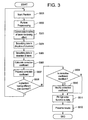
- a phantom is scanned (step S501). Specifically, a phantom is disposed at a position off the center of the X-ray field in the bore 29.
- the phantom is made of a polypropylene or the like and shaped like a cylinder. Phantoms having various diameters are available.
- the present embodiment employs phantoms whose diameters are 35 cm and 48 cm. The phantoms whose diameters are 35 cm and 48 cm are scanned in that order.
- the phantom When a phantom is scanned, the phantom is disposed at a position off the center of the X-ray field in the bore 29. This is because the length of a path traced by X-rays transmitted by the phantom can be differentiated from view to view. In order to highly precisely correct projection information values in terms of the beam-hardening effect, the largest possible number of different projection information values is needed in relation to each channel. When a phantom is disposed at a position off the center of the X-ray field in the bore 29, numerous different projection information values can be acquired from one phantom.
- Fig. 4 shows a phantom 310 disposed in the bore 29 of the scanner gantry 2.
- the phantom 310 has a circular section, and the center of the phantom 310 is located at a position different from the center of the X-ray field in the bore 29.
- An X-ray fan beam into which X-rays generated by the X-ray tube 20 are recomposed by a bow-tie filter is transmitted by the phantom 310 and detected by the X-ray detector 24.
- the X-ray detector 24 has a plurality of X-ray detection elements set in array in a direction in which the X-ray fan beam spreads. Projection information acquired from the phantom 310 is detected on the channels assigned to the X-ray detection elements set in array.
- the X-ray tube 20 and collimator 22 are opposed to the X-ray detector 24 with the bore 29 between them.
- the X-ray tube 20, collimator 22, and X-ray detector 24 are rotated about the bore 29 without any change in their relative positions while being incorporated in the rotary assembly 34, whereby projection information is acquired. Projection information is acquired for each view number associated with a rotation angle, and one sinogram is produced.
- Fig. 5(A) shows an example of a sinogram produced using the phantom 310.
- the sinogram comprises a projection information section defined around the center of one dimension of the sinogram associated with channel numbers, and an air data section defined on both sides of the projection information section along the dimension associated with channel numbers.
- the phantom 310 is disposed off the center of the X-ray field. Therefore, the channel numbers determined with the channel-direction width of the projection information section vary with a change in the rotation angle of the rotary assembly 34, that is, a change in the view number. As shown in Fig. 5(A), the projection information section is tortuous in the direction of view numbers. For the same reason, the channel-direction width of the projection information section varies with a change in the view number.
- Fig. 5(B) is a graph whose axis of abscissas indicates channel numbers and whose axis of ordinates indicates projection information values, wherein projection information of view number j indicated in Fig. 5(A) is pointed out.
- the projection information value is proportional to a length in the phantom 310 over which an X-ray beam is transmitted.
- X-rays passing through near the center of the phantom 310 are transmitted over a large length and provide large projection information values.
- X-rays passing through near the periphery of the phantom 310 are transmitted over a small length and provide small projection information values based on which a semi-circular projection image like the one shown in Fig. 5(B) is displayed.
- a projection information value indicated with view number j and channel number i will be taken for instance.
- An X-ray beam indicated with a dashed line in Fig. 4 provides a view of view number j and falls on a channel of channel number i of the X-ray detector 24.
- a length in the phantom 310 over which the X-ray beam is transmitted shall be I.
- the length I and a projection information value h detected on channel i and indicated in Fig. 5(B) has the relationship expressed below.
- the phantom 310 is located at a position off the center of the X-ray field.
- the length l over which the X-ray beam is transmitted and routed to the channel i varies depending on a view. Consequently, the projection information value h detected on the channel i and indicated in Fig. 5(B) varies depending on a view.
- Fig. 5(C) is a graph whose axis of abscissas indicates view numbers and whose axis of ordinates indicates projection information values, wherein a projection information value detected on the channel of channel number i indicated in Fig. 5(A) is pointed out.
- the projection information value varies depending on a view number, and is proportional to a length in the phantom 310 over which an X-ray beam is transmitted. Therefore, the projection information value is provided as a function represented by a curve having cyclicity as shown in Fig. 5(C).
- Fig. 6 is a block diagram showing files stored in the storage device 66.
- first projection information 601 shown in Fig. 6 is acquired.
- the preprocessing is performed on the sinogram produced from the first projection information, and includes noise removal and sensitivity correction.
- the projection information values Ih are corrected in terms of the beam-hardening effect in order to produce corrected projection information values Ic (step S503).
- second projection information 602 shown in Fig. 6 is produced.
- This file has the beam-hardening effect generally removed from it. However, the beam-hardening effect slightly remains because of a difference of each channel of the X-ray detector 24 from the others.
- Fig. 7(A) illustratively shows an example of the second projection information 602.
- the second projection information 602 is plotted generally semi-circularly because it is acquired from a phantom having a circular section.
- the projection information values Ic sampled in relation to some channels are plotted as pulse-like fluctuations because of a difference in the sensitivity to X-rays of each channel from the others. This is a phenomenon inherent to a channel, and must therefore be corrected in relation to each channel.
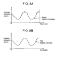
- Fig. 8(A) illustratively shows an example of projection information values sampled from the second projection information 602 in the direction of views in relation to one channel.
- the projection information values Ic sampled in relation to some views are plotted as pulse-like fluctuations.
- the first fitting block 202 smoothes the second projection information 602 in the direction of channels (step S504).
- third' projection information 603 shown in Fig. 6 is produced.
- the third' projection information 603 has the projection information values Ic, which are plotted as fluctuations deriving from a difference of one channel from the others, smoothed and removed.
- Fig. 7(B) illustratively shows an example of the third' projection information 603. A semi-circular curve alone is plotted with the projection information acquired from a phantom having a circular section.
- the first fitting block 202 smoothes the third' projection information 603 in the direction of views (step S505).
- third projection information 604 shown in Fig. 6 is produced.
- the third projection information 604 has projection information values, which are plotted as fluctuations deriving from a difference of one view from the others detected on one channel, smoothed.
- Fig. 8(B) illustratively shows an example of the third projection information.
- the projection information values that are sampled in relation to one channel in the direction of views and that exhibit cyclicity are smoothed.
- the second fitting means 204 calculates a correction coefficient using the second projection information 602 and third projection information 603 (step S506).
- projection information values sampled from the second projection information in relation to channel number i shall be S(j) and projection information values sampled from the third projection information in relation thereto shall be F(j).
- Fig. 9(A) indicates the projection information values sampled in relation to all the view numbers, wherein the axis of abscissas indicates the projection information values S(j) and the axis of ordinates indicates the projection information values F(j).
- the projection information values are generally plotted alone a straight line that passes an origin.
- the straight line represents a correction function relevant to the channel i. Assuming that the slope of the straight line is K 1 i, K 1 i is regarded as correction coefficient information 605 shown in Fig. 6.
- S(j) and F(j) have the relationship expressed below.
- projection information values Ic sampled in relation to channel i from projection information that is acquired from a subject and that is corrected in terms of the beam-hardening effect are multiplied by the correction coefficient Ki of a linear function. Consequently, projection information values Ip are produced as projection information values that have been smoothed and corrected after being acquired from the subject.
- the projection information values S(j) are proportional to the length l over which X-rays are transmitted and which is indicated in Fig. 4. Therefore, the projection information values S(j) and the adopted domain depend on the diameter of the phantom 310 and the position of the phantom in the bore 29.
- correction coefficient Ki is preserved as correction coefficient information 605 in the storage device 66 (step S507).
- step S508 it is determined whether a phantom having a different size is scanned in order to acquire data.
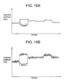
- Fig. 10 is a graph indicating an example of the correction coefficient information 605 produced in relation to each channel.
- Fig. 10(a) indicates correction coefficients calculated using the phantom having a diameter of 35 cm
- Fig. 10(b) indicates correction coefficients calculated using the phantom having a diameter of 48 cm.
- the correction coefficients calculated using the phantoms whose diameters are 35 cm and 48 cm are plotted as similar characteristic curves in relation to the channels. However, the correction coefficients calculated using the phantom having a diameter of 48 cm assume larger values.
- the X-ray detector 24 comprises a plurality of detection modules each assigned a predetermined number of channels.
- the detection modules are manufactured as united bodies in units of sixteen channels. In other words, a predetermined number of detection modules each assigned sixteen channels is arrayed in order to construct the X-ray detector 24.
- the values detected on the channels within the same detection module reflect similar detection characteristics. In other words, the detection modules exhibit different detection characteristics.
- the correction coefficient values arranged orderly in relation to the channels as shown in Fig. 10(a) and Fig. 10(b) contain the dependencies on the detection characteristics of the modules.
- the correction coefficient values arranged orderly in relation to the channels contain the reflections of high-frequency components that depend on the detection characteristics of the respective channels.
- the reflections of high-frequency components in the correction coefficient values indicated in Fig. 10(b) include more reflections of noises than the reflections thereof in the correction coefficient values indicated in Fig. 10(a).
- step S509 After the correction coefficient information 605 is produced using the phantom having a diameter of 48 cm by performing the steps S501 to S507, it is judged whether the correction coefficient information 605 should be modified (step S509).
- correction coefficient information 605 reflecting low signal-to-noise ratios as indicated in Fig. 10(b) is modified. Correction coefficient information produced using the phantom having a small diameter of 35 cm is not modified.
- Fig. 11 includes graphs for explaining an example of a method of modifying correction coefficient information 605.
- SA indicates correction coefficients obtained by removing the reflections of high-frequency components from the correction coefficients that are calculated using the phantom having a diameter of 48 cm and indicated in Fig. 10(b).
- correction coefficients SA contain the dependencies on the detection characteristics of the detection modules but do not contain the reflections of high-frequency components that depend on the detection characteristics of the channels and that degrade signal-to-noise ratios.
- a wave SB indicates the reflections of high-frequency signal components separated from the correction coefficients that are calculated using the phantom having a diameter of 35 cm and indicated in Fig. 10(a).
- the wave SB indicates the reflections of high-frequency signal components in the correction coefficients that are calculated using the phantom having a diameter of 35 cm and that depend on the detection characteristics of the respective channels.
- the reflections of high-frequency components contain the reflections of noises at a smaller ratio than the reflections of high-frequency components in the correction coefficients calculated using the phantom having a diameter of 48 cm.
- correction coefficients SA from which the reflections of high-frequency components are removed are synthesized with the reflections of high-frequency components in the correction coefficients calculated using the phantom having a diameter of 35 cm.
- the resultant correction coefficients are adopted as new correction coefficients SC.
- the modified correction coefficient information is stored as modified correction coefficient information 606 in the storage device 66.
- Fig. 12 shows an example of correction coefficients calculated using two phantoms having different diameters (35 cm and 48 cm).
- domain A comprises projection information values acquired from the phantom having a diameter of 35 cm
- domain B comprises projection information values acquired from the phantom having a diameter of 48 cm.
- a high-order function is fitted to a correction coefficient calculated using the phantom having a diameter of 35 cm and a correction coefficient calculated using the phantom having a diameter of 48 cm (step S511).
- Fig. 13 shows an example of fitting of a high-order function performed using the correction coefficient information indicated in Fig. 12.
- the correction coefficient calculated from domain A composed of small projection information values is thought to be more highly precise than the correction coefficient calculated from domain B composed of large projection information values. Therefore, weights may be applied to the respective domains so that the third-order function will be more highly precisely fitted to the correction coefficient calculated from the domain A, and the correction coefficients in the expression (2) may then be determined.
- step S509 high-order correction function information 607 containing the correction coefficients K0, K1, and K2 is preserved in the storage device 66 (step S509). The process is then terminated.
- projection information values Ic acquired from the subject and corrected in terms of the beam-hardening effect are corrected using correction coefficients K0, K1, and K2 that are calculated in relation to each channel. Corrected projection information values If are then calculated according to the expression (2). Based on the projection information values If, the image reconstruction block 206 reconstructs an image so as to acquire tomographic image information.
- correction coefficient information that is calculated using a large phantom and that reflects low signal-to-noise ratios is corrected using correction coefficient information that is calculated using a phantom ,smaller than the phantom and that reflects high signal-to-noise ratios. Consequently, projection information values corrected in terms of the beam-hardening effect and sampled in relation to each channel can be corrected highly precisely.
Landscapes
- Health & Medical Sciences (AREA)
- Life Sciences & Earth Sciences (AREA)
- Engineering & Computer Science (AREA)
- Medical Informatics (AREA)
- General Health & Medical Sciences (AREA)
- Pathology (AREA)
- Nuclear Medicine, Radiotherapy & Molecular Imaging (AREA)
- Physics & Mathematics (AREA)
- Public Health (AREA)
- Veterinary Medicine (AREA)
- Radiology & Medical Imaging (AREA)
- Animal Behavior & Ethology (AREA)
- Biomedical Technology (AREA)
- Surgery (AREA)
- Optics & Photonics (AREA)
- High Energy & Nuclear Physics (AREA)
- Biophysics (AREA)
- Heart & Thoracic Surgery (AREA)
- Molecular Biology (AREA)
- Theoretical Computer Science (AREA)
- Pulmonology (AREA)
- Chemical & Material Sciences (AREA)
- Analytical Chemistry (AREA)
- Biochemistry (AREA)
- General Physics & Mathematics (AREA)
- Immunology (AREA)
- Nursing (AREA)
- Epidemiology (AREA)
- Apparatus For Radiation Diagnosis (AREA)
Claims (9)
- Röntgenstrahlen-CT-Vorrichtung in der ein Röntgendetektor mit vielen Kanälen verwendet wird, um eine Projektionsinformation, die durch einen Röntgenstrahl, der ein Scan-Feld durchquert hat, geschaffen wird, als mehrere Ansichten aus unterschiedlichen Richtungen zu akquirieren, und in der die Projektionsinformation, die auf jedem der Kanäle detektiert ist, im Sinne von Strahlungshärtungseffekten korrigiert wird, und die aufweist:eine Korrekturkoeffizienten-Erzeugungseinrichtung zur Akquirierung eines in dem Scan-Feld angeordneten Phantoms und zur Berechnung eines Korrekturkoeffizienten aus der Projektionsinformation, der für die Korrektur verwendet wird;eine Korrekturkoeffizienten-Modifizierungseinrichtung zur Modifizierung eines zweiten Korrekturkoeffizienten, den die Korrekturkoeffizienten-Erzeugungseinrichtung unter Verwendung der Projektionsinformation, die von einem zweiten Phantom, das größer ist als das erste Phantom ist, akquiriert ist, und unter Verwendung eines ersten Korrekturkoeffizienten, der die Korrekturkoeffizienten-Erzeugungseinrichtung unter Verwendung der Projektionsinformation berechnet, die von dem ersten Phantom akquiriert ist; undeine Korrektureinrichtung zur Korrektur der Projektionsinformation, die von einem in dem Scan-Feld angeordneten Objekt unter Verwendung des ersten Korrekturkoeffizienten und des korrigierten zweiten Korrekturkoeffizienten akquiriert ist; worinder Röntgendetektor aus mehreren Detektionsmodulen gebildet ist, von denen jedes eine vorbestimmte Anzahl von Kanälen zugeordnet hat; unddie Korrekturkoeffizienten-Modifizierungseinrichtung die Reflektionen der Hochfrequenzkomponenten aus den Korrekturkoeffizientendaten, die unter Verwendung des zweiten Phantoms berechnet sind, separiert, um die Abhängigkeiten von den Detektionscharakteristiken der Detektionsmodule zu belassen, und die Korrekturkoeffizientendaten, aus denen die Reflektionen der Hochfrequenzkomponenten separiert sind, mit den Reflektionen der Hochfrequenzkomponenten in den Korrekturkoeffizientendaten synthetisiert, die unter Verwendung des ersten Phantoms berechnet sind.
- Röntgenstrahlen-CT-Vorrichtung gemäß Anspruch 1, worin die Korrekturkoeffizienten-Erzeugungseinrichtung aufweist:eine Erzeugungseinrichtung zur Erzeugung eines Sinogramms unter Verwendung der ersten Projektionsinformation, die in Bezug auf alle Ansichten von der aus einem Phantom akquirierten Projektionsinformation aufgenommen ist;eine Strahlhärtungs-Korrektureinrichtung zur Korrektur der ersten Projektionsinformation bezogen auf den Strahlhärtungseffekt, um so eine zweite Projektionsinformation zu erzeugen;eine erste Fit-Einrichtung zum Anpassen einer ersten Funktion an die zweite Projektionsinformation, um so eine dritte Projektionsinformation zu erzeugen; undeine zweite Fit-Einrichtung zum Anpassen einer zweiten Funktion an die dritten Projektionsinformationswerte, die als Funktionen geschaffen werden, die unabhängige Variablen der zweiten Projektionsinformationswerte aufweisen, die in Bezug auf alle Ansichten und jeden der Kanäle des Röntgendetektors aufgenommen sind.
- Röntgenstrahlen-CT-Vorrichtung gemäß Anspruch 1, worin das erste und das zweite Phantom kreisförmige Bereiche aufweist und der Durchmesser des zweiten Phantoms größer ist als der Durchmesser des zweiten Phantoms.
- Röntgenstrahlen-CT-Vorrichtung gemäß Anspruch 1, worin die Detektionsmodule für eine Kanaleinheit als verbundener Grundkörper hergestellt werden.
- Röntgenstrahlen-CT-Vorrichtung gemäß Anspruch 1, worin der Röntgendetektor unter Verwendung einer Kombination eines Szintillators und einer Photodiode gebildet ist.
- Röntgenstrahlen-CT-Vorrichtung gemäß Anspruch 1, worin der Röntgenstrahlendetektor eine Röntgenstrahleneinfallsfläche aufweist, die wie eine zylindrische konkave Oberfläche geformt ist.
- Röntgenstrahlen-CT-Vorrichtung gemäß Anspruch 1, worin mehrere Röntgenstrahlendetektionselemente aufweist, die als ein Array in einer Richtung gesetzt sind, in der sich die Röntgenstrahlen in Form eines Fächers ausbreiten.
- Strahlhärtungsnachbehandlungsverfahren für Röntgenstrahlen-CT-Vorrichtungen, gemäß dem ein Röntgenstrahlendetektor verwendet wird, der aus mehreren Detektionsmodulen gebildet ist, wobei jedem eine vorbestimmte Anzahl von Kanälen zugeordnet ist, um eine Projektionsinformation, die durch einen Röntgenstrahl, der ein Scan-Feld durchquert hat, geschaffen ist, als mehrere Ansichten aus verschiedenen Richtungen zu detektieren, und in dem eine Projektionsinformation, die auf jedem Kanal detektiert ist, bezogen auf den Strahlhärtungseffekt korrigiert wird, wobei das Verfahren aufweist:einen Akquirierungsschritt des Scannens eines ersten Phantoms und eines zweiten Phantoms, das größer ist als das erste Phantom, und das zwischen einer Röntgenröhre und dem Röntgendetektor angeordnet ist, und des Akquirierens einer Projektinformation als mehrere Ansichten aus verschiedenen Richtungen unter Verwendung des Röntgendetektors mit Vielfachkanälen;einen Erzeugungsschritt zum Erzeugen eines ersten und eines zweiten Korrekturkoeffizienten, die zur Korrektur verwendet werden, aus der Projektionsinformation, die von dem ersten und dem zweiten Phantom akquiriert sind;eine Korrekturkoeffizienten-Modifizierungsschritt bei dem der zweite Korrekturkoeffizient unter Verwendung des ersten Korrekturkoeffizienten modifiziert wird, indem die Reflektionen der Hochfrequenzkomponenten aus den Korrekturkoeffizientendaten, die unter Verwendung des zweiten Phantoms berechnet sind, separiert wird, um die Abhängigkeiten auf die Detektionscharakteristiken der Detektionsmodule belassen werden, und die Korrekturdaten, von denen die Reflektionen der Hochfrequenzkomponenten separiert Hochfrequenzkomponenten separiert sind, mit den Reflektionen der Hochfrequenzkomponenten in den Korrekturdaten, die unter Verwendung des ersten Phantoms berechnet werden, synthetisiert werden; undeinen Korrekturschritt bei dem die Projektionsinformation, die von dem Objekt, das in dem Scan-Feld positioniert ist, akquiriert wurde, unter Verwendung der ersten Korrekturkoeffizienten und der korrigierten zweiten Korrekturkoeffizienten korrigiert wird.
- Strahlhärtungsnachbehandlungsverfahren für Röntgenstrahlen-CT-Vorrichtungen gemäß Anspruch 8, worin:im Akquirierungsschritt die erste Projektionsinformation von der Projektionsinformation, die von dem ersten und dem zweiten Phantom akquiriert sind, in Bezug auf alle Ansichten aufgenommen wird, um mehrere Sinogramme zu erzeugen;im Erzeugungsschritt die erste Projektionsinformation bezogen auf den Strahlhärtungseffekt korrigiert wird, um eine zweite Projektionsinformation zu erzeugen;eine erste Funktion an die zweite Projektionsinformation angepasst wird, um eine dritte Projektionsinformation zu erzeugen; undeine zweite Funktion an die dritten Projektionsinformationswerte angepasst wird, die als Funktion, die als unabhängige Variablen die zweite Projektionsinformationswerte aufweist, die in Bezug auf alle Ansichten und jedem der Kanäle des Röntgendetektors aufgenommen werden, um die ersten und die zweiten Korrekturkoeffizienten zu berechnen.
Applications Claiming Priority (2)
| Application Number | Priority Date | Filing Date | Title |
|---|---|---|---|
| JP2003112906 | 2003-04-17 | ||
| JP2003112906A JP3950811B2 (ja) | 2003-04-17 | 2003-04-17 | X線ct装置およびビームハードニング後処理方法 |
Publications (2)
| Publication Number | Publication Date |
|---|---|
| EP1468650A1 EP1468650A1 (de) | 2004-10-20 |
| EP1468650B1 true EP1468650B1 (de) | 2007-07-04 |
Family
ID=32906061
Family Applications (1)
| Application Number | Title | Priority Date | Filing Date |
|---|---|---|---|
| EP04252253A Expired - Lifetime EP1468650B1 (de) | 2003-04-17 | 2004-04-16 | System und Methode zur Röntgencomputertomographie mit Korrektur der Strahlaufhärtung |
Country Status (6)
| Country | Link |
|---|---|
| US (1) | US7088800B2 (de) |
| EP (1) | EP1468650B1 (de) |
| JP (1) | JP3950811B2 (de) |
| KR (1) | KR20040090725A (de) |
| CN (1) | CN100466976C (de) |
| DE (1) | DE602004007320T2 (de) |
Families Citing this family (14)
| Publication number | Priority date | Publication date | Assignee | Title |
|---|---|---|---|---|
| JP3802869B2 (ja) * | 2002-12-02 | 2006-07-26 | ジーイー・メディカル・システムズ・グローバル・テクノロジー・カンパニー・エルエルシー | ビームハードニング後処理方法およびx線ct装置 |
| JP4679348B2 (ja) * | 2005-11-22 | 2011-04-27 | ジーイー・メディカル・システムズ・グローバル・テクノロジー・カンパニー・エルエルシー | X線ct装置 |
| JP5491929B2 (ja) * | 2009-04-10 | 2014-05-14 | 株式会社東芝 | X線診断装置及びその方法 |
| KR101146006B1 (ko) * | 2010-05-14 | 2012-05-15 | 경희대학교 산학협력단 | 엑스선 씨티에서의 링 아티팩트 제거방법 및 장치 |
| CN102110288B (zh) * | 2011-02-14 | 2012-06-27 | 东南大学 | 一种ct图像的投影弦图修补方法 |
| US10013518B2 (en) | 2012-07-10 | 2018-07-03 | Kla-Tencor Corporation | Model building and analysis engine for combined X-ray and optical metrology |
| CN103565459B (zh) * | 2013-09-25 | 2015-07-01 | 沈阳东软医疗系统有限公司 | 一种判断成像质量方法和装置 |
| CN104700377B (zh) * | 2013-12-06 | 2019-07-30 | Ge医疗系统环球技术有限公司 | 获得对计算机断层扫描数据进行射束硬化校正的射束硬化校正系数的方法和装置 |
| US10357221B2 (en) | 2014-08-22 | 2019-07-23 | Samsung Electronics Co., Ltd. | Anatomical imaging system with improved detector calibration process |
| EP3829442A4 (de) | 2018-08-03 | 2022-05-11 | NeuroLogica Corporation | Ki-basierte volumenselbstkorrektur für feste und mobile röntgenbildgebungsmodalitäten und andere bildgebungsmodalitäten |
| CN111476856B (zh) * | 2020-04-08 | 2023-06-06 | 中北大学 | 一种多谱ct成像方法 |
| CN112415568B (zh) * | 2020-10-30 | 2023-09-15 | 湖北锐世数字医学影像科技有限公司 | 能量校正方法、装置、设备、系统及计算机可读存储介质 |
| CN114295653B (zh) * | 2021-11-30 | 2023-12-22 | 太仓市林源电线电缆有限公司 | 一种电工铜线的多段式在线连续检测方法 |
| CN115078421B (zh) * | 2022-06-13 | 2025-01-28 | 中国工程物理研究院材料研究所 | 一种基于能谱分析的ct射线硬化伪影校正方法及系统 |
Family Cites Families (16)
| Publication number | Priority date | Publication date | Assignee | Title |
|---|---|---|---|---|
| JPS5594241A (en) * | 1979-01-11 | 1980-07-17 | Hitachi Medical Corp | Xxray transverse layer device |
| US4870666A (en) * | 1986-08-07 | 1989-09-26 | General Electric Company | Computer tomographic phantom |
| FR2656697B1 (fr) * | 1989-12-29 | 1994-01-07 | General Electric Cgr Sa | Procede de mesure de la densite osseuse a l'aide d'un scanner. |
| JP3204701B2 (ja) | 1991-11-14 | 2001-09-04 | ジーイー横河メディカルシステム株式会社 | ビームハードニング補正方法 |
| US5565678A (en) * | 1995-06-06 | 1996-10-15 | Lumisys, Inc. | Radiographic image quality assessment utilizing a stepped calibration target |
| US5867553A (en) * | 1995-11-02 | 1999-02-02 | Analogic Corporation | Computed tomography scanner with reduced power x-ray source |
| JP3779398B2 (ja) * | 1996-11-26 | 2006-05-24 | ジーイー横河メディカルシステム株式会社 | プロジェクションデータ補正方法およびx線ct装置 |
| US5774519A (en) * | 1997-01-30 | 1998-06-30 | Analogic Corporation | Method of and apparatus for calibration of CT scanners |
| US5953444A (en) * | 1997-10-22 | 1999-09-14 | University Of Pennsylvania | Method for improved correction of spectrum hardening artifacts in computed tomography images |
| US6148057A (en) * | 1998-11-02 | 2000-11-14 | Analogic Corporation | Apparatus and method for calibrating detectors in a computed tomography scanner |
| US6505966B1 (en) * | 2000-07-07 | 2003-01-14 | General Electric Company | Method and apparatus for assessing the performance of an x-ray imaging system |
| DE10035984C1 (de) * | 2000-07-24 | 2002-01-31 | Siemens Ag | Röntgen-Computertomographieeinrichtung |
| DE10036142B4 (de) * | 2000-07-25 | 2004-04-29 | Siemens Ag | Röntgen-Computertomographieeinrichtung |
| US6507633B1 (en) * | 2001-02-15 | 2003-01-14 | The Regents Of The University Of Michigan | Method for statistically reconstructing a polyenergetic X-ray computed tomography image and image reconstructor apparatus utilizing the method |
| JP3802869B2 (ja) * | 2002-12-02 | 2006-07-26 | ジーイー・メディカル・システムズ・グローバル・テクノロジー・カンパニー・エルエルシー | ビームハードニング後処理方法およびx線ct装置 |
| JP4142482B2 (ja) * | 2003-04-04 | 2008-09-03 | ジーイー・メディカル・システムズ・グローバル・テクノロジー・カンパニー・エルエルシー | X線ct装置 |
-
2003
- 2003-04-17 JP JP2003112906A patent/JP3950811B2/ja not_active Expired - Fee Related
-
2004
- 2004-04-15 US US10/825,526 patent/US7088800B2/en not_active Expired - Fee Related
- 2004-04-16 DE DE602004007320T patent/DE602004007320T2/de not_active Expired - Lifetime
- 2004-04-16 CN CNB2004100368838A patent/CN100466976C/zh not_active Expired - Fee Related
- 2004-04-16 EP EP04252253A patent/EP1468650B1/de not_active Expired - Lifetime
- 2004-04-16 KR KR1020040026034A patent/KR20040090725A/ko not_active Withdrawn
Also Published As
| Publication number | Publication date |
|---|---|
| DE602004007320T2 (de) | 2008-03-06 |
| JP2004313524A (ja) | 2004-11-11 |
| US20040208290A1 (en) | 2004-10-21 |
| CN100466976C (zh) | 2009-03-11 |
| DE602004007320D1 (de) | 2007-08-16 |
| JP3950811B2 (ja) | 2007-08-01 |
| CN1550214A (zh) | 2004-12-01 |
| EP1468650A1 (de) | 2004-10-20 |
| KR20040090725A (ko) | 2004-10-26 |
| US7088800B2 (en) | 2006-08-08 |
Similar Documents
| Publication | Publication Date | Title |
|---|---|---|
| US7444010B2 (en) | Method and apparatus for the reduction of artifacts in computed tomography images | |
| US6421411B1 (en) | Methods and apparatus for helical image artifact reduction | |
| US7023951B2 (en) | Method and apparatus for reduction of artifacts in computed tomography images | |
| US6618466B1 (en) | Apparatus and method for x-ray scatter reduction and correction for fan beam CT and cone beam volume CT | |
| JP3894993B2 (ja) | X線源に供給されるx線管電流を変調させるシステム | |
| EP1475039B1 (de) | Korrektur der Strahlaufhärtung und der mangelnden Gleichförmigkeit der Detektorkanäle in einem Computertomographen mittels eines Phantoms mit länglichem, z.B. elliptischem Querschnitt | |
| EP1113396B1 (de) | Verfahren und Gerät zur Mehrschichttomografie mit partieller Abtastung | |
| US8964933B2 (en) | X-ray computed tomography apparatus, medical image processing apparatus, X-ray computed tomography method, and medical image processing method | |
| EP1468650B1 (de) | System und Methode zur Röntgencomputertomographie mit Korrektur der Strahlaufhärtung | |
| US6944258B2 (en) | Beam hardening post-processing method and X-ray CT apparatus | |
| JP2000000236A (ja) | 高減衰性物体のためのア―ティファクト補正 | |
| US6408042B1 (en) | Methods and apparatus for cone beam artifact suppression in scanning imaging systems | |
| JPH09285460A (ja) | 物体の断層写真画像を発生するシステム | |
| JPH10295684A (ja) | 計算機式断層写真法システムにおいてデータ収集システムのゲインを変調させると共にシステム走査中に収集されたデータを補正する方法及びシステム | |
| US6332013B1 (en) | Methods and apparatus for tilted helical reconstruction multislice CT | |
| US6351514B1 (en) | Slice-adaptive multislice helical weighting for computed tomography imaging | |
| US5812628A (en) | Methods and apparatus for detecting partial volume image artifacts | |
| JP2000023966A (ja) | 螺旋再構成アルゴリズム | |
| US8385620B2 (en) | Method and system for multi-detector-row computed tomography utilizing projection data up-sampling with shift | |
| JPH0919426A (ja) | 計算機式断層写真法システム | |
| US6647084B1 (en) | Method and apparatus for filtering projection data of a helical scan | |
| EP1103221B1 (de) | Verfahren und Gerät zur Optimisierung der Bildqualität vom Komputertomographen mit optimaler Datenerfassung | |
| US6091840A (en) | Methods and apparatus for single slice helical image reconstruction in a computed tomography system | |
| US6408088B1 (en) | Methods and apparatus for single slice helical image reconstruction in a computed tomography system | |
| JP2000083946A (ja) | プロジェクション補正方法および装置並びに放射線断層撮影装置 |
Legal Events
| Date | Code | Title | Description |
|---|---|---|---|
| PUAI | Public reference made under article 153(3) epc to a published international application that has entered the european phase |
Free format text: ORIGINAL CODE: 0009012 |
|
| AK | Designated contracting states |
Kind code of ref document: A1 Designated state(s): AT BE BG CH CY CZ DE DK EE ES FI FR GB GR HU IE IT LI LU MC NL PL PT RO SE SI SK TR |
|
| AX | Request for extension of the european patent |
Extension state: AL HR LT LV MK |
|
| 17P | Request for examination filed |
Effective date: 20050420 |
|
| AKX | Designation fees paid |
Designated state(s): DE FR GB NL |
|
| GRAP | Despatch of communication of intention to grant a patent |
Free format text: ORIGINAL CODE: EPIDOSNIGR1 |
|
| GRAS | Grant fee paid |
Free format text: ORIGINAL CODE: EPIDOSNIGR3 |
|
| GRAA | (expected) grant |
Free format text: ORIGINAL CODE: 0009210 |
|
| AK | Designated contracting states |
Kind code of ref document: B1 Designated state(s): DE FR GB NL |
|
| REG | Reference to a national code |
Ref country code: GB Ref legal event code: FG4D |
|
| REF | Corresponds to: |
Ref document number: 602004007320 Country of ref document: DE Date of ref document: 20070816 Kind code of ref document: P |
|
| EN | Fr: translation not filed | ||
| PLBE | No opposition filed within time limit |
Free format text: ORIGINAL CODE: 0009261 |
|
| STAA | Information on the status of an ep patent application or granted ep patent |
Free format text: STATUS: NO OPPOSITION FILED WITHIN TIME LIMIT |
|
| 26N | No opposition filed |
Effective date: 20080407 |
|
| PG25 | Lapsed in a contracting state [announced via postgrant information from national office to epo] |
Ref country code: FR Free format text: LAPSE BECAUSE OF FAILURE TO SUBMIT A TRANSLATION OF THE DESCRIPTION OR TO PAY THE FEE WITHIN THE PRESCRIBED TIME-LIMIT Effective date: 20080229 |
|
| GBPC | Gb: european patent ceased through non-payment of renewal fee |
Effective date: 20080416 |
|
| PG25 | Lapsed in a contracting state [announced via postgrant information from national office to epo] |
Ref country code: GB Free format text: LAPSE BECAUSE OF NON-PAYMENT OF DUE FEES Effective date: 20080416 |
|
| PGFP | Annual fee paid to national office [announced via postgrant information from national office to epo] |
Ref country code: DE Payment date: 20130429 Year of fee payment: 10 |
|
| PGFP | Annual fee paid to national office [announced via postgrant information from national office to epo] |
Ref country code: NL Payment date: 20130426 Year of fee payment: 10 |
|
| REG | Reference to a national code |
Ref country code: DE Ref legal event code: R119 Ref document number: 602004007320 Country of ref document: DE |
|
| REG | Reference to a national code |
Ref country code: NL Ref legal event code: V1 Effective date: 20141126 |
|
| REG | Reference to a national code |
Ref country code: DE Ref legal event code: R119 Ref document number: 602004007320 Country of ref document: DE Effective date: 20141101 |
|
| PG25 | Lapsed in a contracting state [announced via postgrant information from national office to epo] |
Ref country code: DE Free format text: LAPSE BECAUSE OF NON-PAYMENT OF DUE FEES Effective date: 20141101 |
|
| PG25 | Lapsed in a contracting state [announced via postgrant information from national office to epo] |
Ref country code: NL Free format text: LAPSE BECAUSE OF NON-PAYMENT OF DUE FEES Effective date: 20141101 |