EP1468756B1 - Verfahren und Vorrichtung zum Biegen von rohrförmigen Werkstücken mit veränderlichem Biegeradius - Google Patents
Verfahren und Vorrichtung zum Biegen von rohrförmigen Werkstücken mit veränderlichem Biegeradius Download PDFInfo
- Publication number
- EP1468756B1 EP1468756B1 EP04101562A EP04101562A EP1468756B1 EP 1468756 B1 EP1468756 B1 EP 1468756B1 EP 04101562 A EP04101562 A EP 04101562A EP 04101562 A EP04101562 A EP 04101562A EP 1468756 B1 EP1468756 B1 EP 1468756B1
- Authority
- EP
- European Patent Office
- Prior art keywords
- bending
- vice
- tubular element
- heads
- actuators
- Prior art date
- Legal status (The legal status is an assumption and is not a legal conclusion. Google has not performed a legal analysis and makes no representation as to the accuracy of the status listed.)
- Expired - Lifetime
Links
Images



Classifications
-
- B—PERFORMING OPERATIONS; TRANSPORTING
- B21—MECHANICAL METAL-WORKING WITHOUT ESSENTIALLY REMOVING MATERIAL; PUNCHING METAL
- B21D—WORKING OR PROCESSING OF SHEET METAL OR METAL TUBES, RODS OR PROFILES WITHOUT ESSENTIALLY REMOVING MATERIAL; PUNCHING METAL
- B21D7/00—Bending rods, profiles, or tubes
- B21D7/08—Bending rods, profiles, or tubes by passing between rollers or through a curved die
-
- B—PERFORMING OPERATIONS; TRANSPORTING
- B21—MECHANICAL METAL-WORKING WITHOUT ESSENTIALLY REMOVING MATERIAL; PUNCHING METAL
- B21D—WORKING OR PROCESSING OF SHEET METAL OR METAL TUBES, RODS OR PROFILES WITHOUT ESSENTIALLY REMOVING MATERIAL; PUNCHING METAL
- B21D7/00—Bending rods, profiles, or tubes
- B21D7/12—Bending rods, profiles, or tubes with program control
Definitions
- the invention concerns a method for bending tubular elements to an adjustable radius of curvature and a bending machine that implements said method for bending tubular elements, in accordance with the preamble of the respective independent claim (see US-A-4 604 885).
- apposite bending machines which basically comprise a vice to hold the tubular element firmly in bending position and a bending head provided with a female die and a male die that are set rotating around an axis by power means.
- the bending head can be moved with respect to the vice, so that the tubular element can be bent in different positions.
- bending machines are equipped with two bending heads positioned at the sides of the vice, in such a way as to obtain two bends at the same time.
- the bending machines of the known type have the drawback that to vary the radius of curvature it is necessary to use dies with different average radius; therefore, the user must have several male and female dies, according to the different radiuses of curvature to be obtained on the same tubular element.
- Bending machines with a single bending head are also known, in which the vice that holds the tubular element in bending position can be moved with respect to the bending head.
- the invention intends to overcome the drawback mentioned above, through the implementation of a method that makes it possible to obtain two bends in two different positions on the tubular element, at least one of which with variable radius of curvature, with no need to replace the bending female and male dies.
- the invention also aims to make bends with fixed radius of curvature in any position on the same tubular element.
- a further aim is to make one bend with fixed radius of curvature and another bend with variable radius of curvature at the same time on the same tubular element.
- a bending method for bending tubular elements with a bending machine of the type comprising a central vice and two movable bending heads provided with bending means, positioned one on the right side and one on the left side of said vice, wherein according to the main claim said bending method comprises the following operations:
- the value of the angular displacement of the bending means during rotation and the value of the linear displacement of the bending head during travel are variable and independent of each other.
- the profile of the bend to carry out is defined by properly combining the value of the angular displacement of the bending means and the value of the linear displacement of the bending head.
- the bending machine that implements the method described above comprises:
- the vice is also provided with power means suited to move it on a horizontal plane in orthogonal direction with respect to the movement of the bending heads along the base, in order to allow the tube to be adapted to the different equipment installed on the heads.
- the bending heads are provided with means to move them vertically, in order to adapt the bending equipment to the tubular element that must be bent.
- the bending machine that carries out the method of the invention can be derived from a bending machine of the known type, comprising a base with central vice and two side heads positioned one on the right and one on the left of the vice, which is modified through the application of the above mentioned electronic storage, processing and control unit to manage the power means and the actuators.
- the combination of the linear movement of the bending head with the rotation of the bending means gives the opportunity to make bends with variable radius of curvature in different positions on the tubular element.
- the machine object of the invention thus makes it possible to obtain two bends with variable radius of curvature at the same time on the same tubular element, thus increasing productivity in comparison with the known bending machines that allow bends with variable radius of curvature to be made only one by one.
- the machine object of the invention may in any case be used also to make bends with fixed radius of curvature, if during the bending operation the bending heads are not moved longitudinally with respect to the vice.
- Another advantage is represented by the fact that the machine object of the invention can make one bend with fixed radius of curvature and one bend with variable radius of curvature at the same time, by keeping only one of the two bending heads fixed.
- a further advantage is represented by the fact that the movement of the vice on the horizontal plane perpendicularly to the movement of the bending heads and the vertical movement of the latter allows the tube that must be bent to be adapted to different bending equipment.
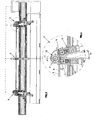
- the bending method object of the invention is described with reference to a bending machine, indicated as a whole by 1, which can be seen in a front view in Figures 1, 3, 5 and also in the successive Figures from 7 to 12, where it is represented in total or partial axonometric view.
- the bending machine 1 comprises a base 2 that supports a vice, indicated as a whole by 3, practically positioned at the centre of the base 2, wherein on the right and left side of said vice there are two bending heads, indicated by 4 and 5 , respectively.
- the two bending heads 4 and 5 can be moved along the base with respect to the vice 3, with a linear sliding movement.
- each bending head can be moved in a direction parallel to the longitudinal axis X of the tubular element to be bent T, which is practically placed in horizontal position and supported by the bending heads 4 and 5 and by the vice 3 .
- clamping means for the tubular element to be bent T which are indicated as a whole by 8 and include, as can be observed in greater detail in Figures 11 and 12, a pair of opposing jaws 8a, 8b, between which the tubular element to be bent T is interposed.
- First power means indicated as a whole by 9, of the known type, which can be hydraulic, pneumatic or electric, set the disc 6 rotating clockwise or anticlockwise, as indicated by the arrows 6a around the longitudinal axis X, to define the angular position where the tubular element T must be bent.
- first actuators of the known type and not represented are combined with the jaws 8a , 8b to open and close them with respect to the tubular element T.
- each bending head 4, 5 substantially comprises a carriage 10 supported by the base 2, to which a closing slide 14 and bending means indicated as a whole by 11 are connected, said bending means comprising a bending female die 12 that cooperates with a bending arm 13.
- the bending female die 12 may be simple or with several grooves.
- the carriage 10 is associated with second power means, not represented in the drawing for the sake of simplicity and of the known type, which move the carriage 10 and therefore the whole bending head in both the directions indicated by the arrows 10a along the base 2, according to a longitudinal direction parallel to the longitudinal axis X defined by the tubular element T.
- the female die 12 it is of the simplest type known, in fact it consists of a grooved roller 12a that defines a rotation axis Y substantially orthogonal to the longitudinal axis X of the tubular element T , around which it rotates owing to the action of second actuators, not represented in the drawing and of the known type.
- the bending arm 13 rotates around the same axis Y, owing to the action of third actuators not represented and of the known type, and supports a male die 15 constituted by a grooved roller 15a supported by a slide 16 that travels on the bending arm 13 .
- the female die may also be provided with several grooves.
- the slide 16 is also combined with fourth actuators, not represented, but of the known type, which serve to move the male die 15 with respect to the female die 12, in order to bring it near to or move it far from the tubular element T.
- closing slide 14 it is provided with an opposing grooved roller 17 and is associated with fifth actuators, not represented and of the known type, which serve to move it with respect to the tubular element T.
- All the power means of the disc 6, the vice 3 and the carriage 10 of each bending head 4, 5, as well as the actuators of the jaws 8a, 8b, the vice 3, the female die 12, the bending arm 13, the slide 16 supporting the male die 15 and the slide 14 supporting the opposing roller 17, are actuators of the known type that, according to the requirements regarding torque, speed and power, can be hydraulic, pneumatic or electric.
- drive kinematic motions of the known type, which include screw-nut or pinion-rack connections, or similar ones.
- the vice 3 is slidingly supported by slides 3a obtained in the base 2 , along which it can be moved in a direction parallel to the direction of rotation Y of the female die 12 , owing to the action of third power means 20 , as can be observed in particular in Figures 7, 9, 11 and 12.
- Each bending head 4 , 5 is provided in turn with fourth power means, not visible in the drawings, suited to move it in a vertical direction Z , indicated in Figure 8, to adapt its position with respect to the tubular element T.
- the power means and the actuators are interfaced with an electronic storage, processing and control unit 20 suited to combine the rotation of the bending means 11 with the linear movement of the bending heads 4, 5 along the base 2 according to preset values, to obtain bends with variable radius of curvature on the tubular element T.
- the bending method object of the invention is described with reference to the Figures from 1 to 6 and its first step consists in positioning the tubular element to be bent T horizontally, as can be seen in Figure 1, between the bending heads 4 , 5 and the vice 3 , which are open.
- the tubular element T is thus locked in the vice 3 by clamping the jaws 8a, 8b and between the bending heads 4, 5 by bringing near it the opposing roller 17 of the closing slide 14.
- the electronic unit 20 makes the female die 12 and the bending arm 13 rotate anticlockwise around the axis Y of a preset angle ⁇ , as shown in Figure 4, thus forcing the male die 15 to start bending the tubular element T following the profile of the female die 12.
- the unit 20 stops the rotation of the bending arm 13 and forces the bending head to move leftwards as indicated by the arrow S shown in Figure 6.
- the tubular element T is bent continuously with a radius R whose value is determined by the combination of the value of the angular rotation ⁇ applied to the bending arm 13 with the movement towards the vice 3 applied to the bending head 4 .
- the tubular element to be bent T is positioned in the vice 3 between the bending heads 4 and 5, as shown in Figure 7, and is locked in bending position.
- the bend with fixed radius is then carried out through the clockwise rotation of the bending arm 13, as shown in Figure 8, thus obtaining the first bend C1 with fixed radius of curvature.
Landscapes
- Engineering & Computer Science (AREA)
- Mechanical Engineering (AREA)
- Bending Of Plates, Rods, And Pipes (AREA)
- Diaphragms For Electromechanical Transducers (AREA)
Claims (14)
- Biegemethode zum Krümmen von Rohrelementen mit einer Biegemaschine (1) des Typs mit einem zentralen Schraubstock (3) und zwei mit Biegemitteln (11) versehenen beweglichen Biegeköpfen (4, 5), von denen einer an der rechten und einer an der linken Seite des Schraubstocks (3) positioniert ist, folgende Vorgänge umfassend:- Positionierung eines Rohrelements (T) im Schraubstock (3) und zwischen den Biegeköpfen (4, 5);- Halten des Rohrelements (T) in Biegeposition im Schraubstock (3) und zwischen den Biegeköpfen (4, 5);- Drehung der Biegemittel (11) der Biegeköpfe (4, 5) zum Biegen des Rohrelemente (T);dadurch gekennzeichnet, dass die Drehung der Biegemittel (11) kombiniert ist mit dem Verfahrhub der Biegeköpfe (4, 5) bezüglich des Schraubstocks (3), um Biegungen mit variablem Krümmungsradius des Rohrelements (T) durchzuführen.
- Biegemethode gemäß Patentanspruch 1), dadurch gekennzeichnet, dass sie die Bewegung des Rohrelements (T) in eine zu der von ihm definierten Längsachse (X) lotrechte Richtung einschließt, bevor es in der Biegeposition im Schraubstock (3) eingespannt wird, ausgerichtet auf den Schraubstock (3) und die Biegeköpfe (4, 5).
- Biegemethode gemäß Patentanspruch 1), dadurch gekennzeichnet, dass die Werte der Winkelverschiebung (α) der Biegemittel (11) während der Drehung sowie jene der linearen Verschiebung jedes der Biegeköpfe (4, 5) während ihres Verfahrhubs variabel sind.
- Biegemethode gemäß Patentanspruch 3), dadurch gekennzeichnet, dass die Werte der Winkelverschiebung (α) der Biegemittel (11) während der Drehung sowie jene der linearen Verschiebung jedes der Biegeköpfe (4, 5) während ihres Verfahrhubs voneinander unabhängig sind.
- Biegemaschine (1) zum Biegen von Rohrelementen (T), Folgendes umfassend:- eine im Wesentlichen längs geformte Basis (2);- einen an der Basis (2) befestigten, zentralen Schraubstock (3) mit Mitteln (8) zum Einklemmen eines zu biegenden Rohrelements (T);- zwei sich an der Basis (2) entlang bewegende Biegeköpfe (4, 5) mit Mitteln (11) zum Biegen des Rohrelements (T), von denen einer rechts und einer links vom Schraubstock (3) angebracht ist;- Antriebsmittel zum Drehen des Schraubstocks (3) und zum Bewegen der Biegeköpfe (4, 5) an der Basis (2) entlang;- Stellglieder für die Drehung der Biegemittel (11),dadurch gekennzeichnet, dass die Antriebsmittel und die Stellglieder über eine Schnittstelle mit einer elektronischen Speicher-, Verarbeitungs- und Steuereinheit (20) verbunden sind, die geeignet ist, die Drehung der Biegemittel (11) mit der linearen Bewegung der Biegeköpfe (4, 5) entlang der Basis (2) gemäß voreingestellten Werten zu kombinieren, um Biegungen mit variablem Krümmungsradius des Rohrelements (T) zu erzielen.
- Biegemaschine (1) gemäß Patentanspruch 5), dadurch gekennzeichnet, dass der Schraubstock (3) eine im Wesentlichen kreisförmige Scheibe (6) umfasst, die mit den Antriebsmitteln (9) verbunden ist, um in Drehung entlang ihrer Längsachse versetzt zu werden, und ein Radial-Langloch (7) aufweist, dessen Länge größer ist als sein Radius, in dem sich Mittel (8) befinden, um das zu biegende Rohrelement (T) einzuklemmen.
- Biegemaschine (1) gemäß Patentanspruch 6), dadurch gekennzeichnet, dass die Klemmmittel (8) des Schraubstocks ein Paar einander entgegengesetzter Klemmbacken (8a, 8b) umfassen, welche an dem Rohrelement (T) gegenüberliegenden Seiten angebracht und mit ersten Stellgliedern verbunden sind, die sie gegen das Rohrelement (T) bewegen.
- Biegemaschine (1) gemäß Patentanspruch 5), dadurch gekennzeichnet, dass jeder der Biegeköpfe (4, 5) Folgendes umfasst:- einen Schlitten (10), der mit den Antriebsmitteln verbunden ist, um ihn entlang der Basis (2) zu bewegen;- Biegemittel (11), die mit dem Schlitten (10) verbunden sind und einen Außen-Biegestempel (12) umfassen, der eine im Wesentlichen zur Längsachse (X) des Rohrelements (T) lotrecht stehende Drehachse (Y) definiert, um welche sich der Außenstempel (12) infolge der Wirkung zweiter Stellglieder dreht, und einen Biegearm (13), der die selbe Drehachse (Y) wie jene des Außenstempels definiert, um welche er sich infolge der Wirkung dritter Stellglieder dreht und der einen Innen-Biegestempel (15) trägt, der dem Außenstempel (12) gegenüber positioniert ist, bezüglich dessen er durch vierte Stellglieder bewegt wird;- einen Schließschieber (14) mit einer Gegenwalze (17) gegenüber dem Außenstempel (12) und neben dem Innenstempel (15), wobei dieser Schließschieber (14) mit fünften Stellgliedern verbunden ist, die ihn bezüglich des Rohrelements (T) bewegen.
- Biegemaschine (1) gemäß Patentanspruch 5) oder 6), dadurch gekennzeichnet, dass die Antriebsmittel Folgendes umfassen:- erste, mit dem Schraubstock (3) verbundene Antriebsmittel (9), die geeignet sind, diesen in Drehung um seine eigene Drehachse (Y) zu versetzen;- zweite, mit dem Biegekopf (4, 5) verbundene Antriebsmittel, die geeignet sind, ihn entlang der Basis (2) an der Längsachse (X) des Rohrelements (T) zu bewegen.
- Biegemaschine (1) gemäß Patentanspruch 5), dadurch gekennzeichnet, dass sie auch dritte, mit dem Schraubstock (3) verbundene Antriebsmittel (20) umfasst, die geeignet sind, den Schraubstock auf einer waagerechten Ebene bezüglich der Bewegung der Biegeköpfe (4, 5) in lotrechte Richtung zu bewegen.
- Biegemaschine (1) gemäß Patentanspruch 5), dadurch gekennzeichnet, dass sie auch vierte, mit jedem der Biegeköpfe (4, 5) verbundene Antriebsmittel umfasst, um jeden Biegekopf in senkrechte Richtung (Z) zu bewegen.
- Biegemaschine (1) gemäß Patentanspruch 6) oder 8), dadurch gekennzeichnet, dass die Stellglieder und Antriebsmittel hydraulisch sind.
- Biegemaschine (1) gemäß Patentanspruch 6), 8) oder 9), dadurch gekennzeichnet, dass die Stellglieder und Antriebsmittel elektrisch sind.
- Biegemaschine (1) gemäß Patentanspruch 6), 8) oder 9), dadurch gekennzeichnet, dass die Stellglieder und Antriebsmittel pneumatisch sind.
Applications Claiming Priority (2)
| Application Number | Priority Date | Filing Date | Title |
|---|---|---|---|
| IT000076A ITVI20030076A1 (it) | 2003-04-15 | 2003-04-15 | Metodo e macchina per realizzare la curvatura a raggio |
| ITVI20030076 | 2003-04-15 |
Publications (2)
| Publication Number | Publication Date |
|---|---|
| EP1468756A1 EP1468756A1 (de) | 2004-10-20 |
| EP1468756B1 true EP1468756B1 (de) | 2006-07-26 |
Family
ID=32894207
Family Applications (1)
| Application Number | Title | Priority Date | Filing Date |
|---|---|---|---|
| EP04101562A Expired - Lifetime EP1468756B1 (de) | 2003-04-15 | 2004-04-15 | Verfahren und Vorrichtung zum Biegen von rohrförmigen Werkstücken mit veränderlichem Biegeradius |
Country Status (4)
| Country | Link |
|---|---|
| EP (1) | EP1468756B1 (de) |
| AT (1) | ATE333956T1 (de) |
| DE (1) | DE602004001620T2 (de) |
| IT (1) | ITVI20030076A1 (de) |
Cited By (1)
| Publication number | Priority date | Publication date | Assignee | Title |
|---|---|---|---|---|
| US11229938B2 (en) * | 2015-08-27 | 2022-01-25 | M.E.P. Macchine Eletrroniche Piegatrici, S.p.A. | Combined machine for working wire rod and corresponding working method |
Families Citing this family (8)
| Publication number | Priority date | Publication date | Assignee | Title |
|---|---|---|---|---|
| CN103567262B (zh) * | 2012-08-07 | 2015-08-05 | 浙江摩多巴克斯汽配有限公司 | 弯管机的机头 |
| CN103801602B (zh) * | 2012-11-06 | 2016-11-02 | 浙江摩多巴克斯科技股份有限公司 | 带管端成型功能的弯管机 |
| CN103846326B (zh) * | 2012-11-29 | 2016-03-23 | 浙江摩多巴克斯科技股份有限公司 | 弯管机 |
| EP3151985B1 (de) * | 2014-06-06 | 2021-12-01 | M.E.P. Macchine Elettroniche Piegatrici S.p.A. | Biegemaschine und entsprechendes verfahren |
| CN106825156B (zh) * | 2015-12-07 | 2019-03-05 | 上海乐翱机械设计有限公司 | 一种弯管机 |
| CN106238524B (zh) * | 2016-07-26 | 2018-06-08 | 中核(天津)机械有限公司 | 沿切向打开的带锥管件弯形模具 |
| JP6852628B2 (ja) * | 2017-09-12 | 2021-03-31 | トヨタ自動車株式会社 | 平角線曲げ装置 |
| CN113020354B (zh) * | 2021-03-02 | 2022-02-22 | 南京航空航天大学 | 一种预焊分叉支管的管件成形加工方法及成形装置 |
Family Cites Families (3)
| Publication number | Priority date | Publication date | Assignee | Title |
|---|---|---|---|---|
| DE2546695C3 (de) * | 1975-10-17 | 1987-04-16 | Daiichi Koshuha Kogyo K.K., Tokio/Tokyo | Vorrichtung zum kontinuierlichen Biegen von langgestreckten Werkstücken |
| DE8309569U1 (de) * | 1983-03-31 | 1985-02-21 | Lang, Thomas Peter, Dipl.-Wirtsch.-Ing., 6120 Michelstadt | Maschine zum biegen von strangmaterial |
| JPH04127919A (ja) * | 1990-09-17 | 1992-04-28 | Opton Co Ltd | 曲げ装置 |
-
2003
- 2003-04-15 IT IT000076A patent/ITVI20030076A1/it unknown
-
2004
- 2004-04-15 DE DE602004001620T patent/DE602004001620T2/de not_active Expired - Lifetime
- 2004-04-15 AT AT04101562T patent/ATE333956T1/de not_active IP Right Cessation
- 2004-04-15 EP EP04101562A patent/EP1468756B1/de not_active Expired - Lifetime
Cited By (1)
| Publication number | Priority date | Publication date | Assignee | Title |
|---|---|---|---|---|
| US11229938B2 (en) * | 2015-08-27 | 2022-01-25 | M.E.P. Macchine Eletrroniche Piegatrici, S.p.A. | Combined machine for working wire rod and corresponding working method |
Also Published As
| Publication number | Publication date |
|---|---|
| DE602004001620D1 (de) | 2006-09-07 |
| ATE333956T1 (de) | 2006-08-15 |
| ITVI20030076A1 (it) | 2004-10-16 |
| EP1468756A1 (de) | 2004-10-20 |
| DE602004001620T2 (de) | 2007-07-19 |
Similar Documents
| Publication | Publication Date | Title |
|---|---|---|
| JP3685526B2 (ja) | パイプの曲げ加工装置 | |
| US4242898A (en) | Machine for bending the edges of rectangular sheets of metal | |
| EP1468756B1 (de) | Verfahren und Vorrichtung zum Biegen von rohrförmigen Werkstücken mit veränderlichem Biegeradius | |
| JP4591908B2 (ja) | パイプの曲げ加工装置 | |
| US4944176A (en) | Metal plate bending machine | |
| KR101316920B1 (ko) | 벤딩 가공 장치 | |
| US5479810A (en) | Method for producing form wound stator coils | |
| CA2182329C (en) | Cnc-controlled pipe bending machine | |
| CN107005016B (zh) | 定心单元、压接装置和线缆加工设备 | |
| US10328475B2 (en) | Method and device for bending of strand-shaped workpieces | |
| CN111790880A (zh) | 用于生产装饰链的自动化机器和生产装饰链的工艺 | |
| JPS59183938A (ja) | 索状材料を曲げる機械 | |
| US6854311B2 (en) | Bending machine for tubing, bar and the like | |
| JP2002192236A (ja) | 長尺材の曲げ加工装置 | |
| HU213555B (en) | Structure for the clamping and positioning of the tools of bending machines and a bending machine with this type of structure | |
| JP3966548B2 (ja) | パイプの曲げ加工装置 | |
| US6416449B1 (en) | Device for changing bending tools | |
| US6345525B1 (en) | Tube bending machine, magazine device thereof, and method for loading | |
| CA1333355C (en) | Method and apparatus for forming a barrel coil spring | |
| US20050056071A1 (en) | Orbital machine for bending tubes | |
| US20150040637A1 (en) | Roller Clamp for Wire Processing | |
| US11318516B2 (en) | Bending group of a paneling machine tool | |
| US8220304B2 (en) | Machine for cambering, forming, folding or bending bars, wires or extruded shapes | |
| JP2014213356A (ja) | ベンダー及びワークの取出し方法 | |
| US20230134903A1 (en) | Bending machine |
Legal Events
| Date | Code | Title | Description |
|---|---|---|---|
| PUAI | Public reference made under article 153(3) epc to a published international application that has entered the european phase |
Free format text: ORIGINAL CODE: 0009012 |
|
| AK | Designated contracting states |
Kind code of ref document: A1 Designated state(s): AT BE BG CH CY CZ DE DK EE ES FI FR GB GR HU IE IT LI LU MC NL PL PT RO SE SI SK TR |
|
| AX | Request for extension of the european patent |
Extension state: AL HR LT LV MK |
|
| 17P | Request for examination filed |
Effective date: 20050420 |
|
| AKX | Designation fees paid |
Designated state(s): AT BE BG CH CY CZ DE DK EE ES FI FR GB GR HU IE IT LI LU MC NL PL PT RO SE SI SK TR |
|
| GRAP | Despatch of communication of intention to grant a patent |
Free format text: ORIGINAL CODE: EPIDOSNIGR1 |
|
| GRAS | Grant fee paid |
Free format text: ORIGINAL CODE: EPIDOSNIGR3 |
|
| RIN1 | Information on inventor provided before grant (corrected) |
Inventor name: PEDRAZZOLI, ANTONIO MARIA |
|
| GRAA | (expected) grant |
Free format text: ORIGINAL CODE: 0009210 |
|
| AK | Designated contracting states |
Kind code of ref document: B1 Designated state(s): AT BE BG CH CY CZ DE DK EE ES FI FR GB GR HU IE IT LI LU MC NL PL PT RO SE SI SK TR |
|
| PG25 | Lapsed in a contracting state [announced via postgrant information from national office to epo] |
Ref country code: RO Free format text: LAPSE BECAUSE OF FAILURE TO SUBMIT A TRANSLATION OF THE DESCRIPTION OR TO PAY THE FEE WITHIN THE PRESCRIBED TIME-LIMIT Effective date: 20060726 Ref country code: LI Free format text: LAPSE BECAUSE OF FAILURE TO SUBMIT A TRANSLATION OF THE DESCRIPTION OR TO PAY THE FEE WITHIN THE PRESCRIBED TIME-LIMIT Effective date: 20060726 Ref country code: FI Free format text: LAPSE BECAUSE OF FAILURE TO SUBMIT A TRANSLATION OF THE DESCRIPTION OR TO PAY THE FEE WITHIN THE PRESCRIBED TIME-LIMIT Effective date: 20060726 Ref country code: CH Free format text: LAPSE BECAUSE OF FAILURE TO SUBMIT A TRANSLATION OF THE DESCRIPTION OR TO PAY THE FEE WITHIN THE PRESCRIBED TIME-LIMIT Effective date: 20060726 Ref country code: IT Free format text: LAPSE BECAUSE OF FAILURE TO SUBMIT A TRANSLATION OF THE DESCRIPTION OR TO PAY THE FEE WITHIN THE PRESCRIBED TIME-LIMIT;WARNING: LAPSES OF ITALIAN PATENTS WITH EFFECTIVE DATE BEFORE 2007 MAY HAVE OCCURRED AT ANY TIME BEFORE 2007. THE CORRECT EFFECTIVE DATE MAY BE DIFFERENT FROM THE ONE RECORDED. Effective date: 20060726 Ref country code: NL Free format text: LAPSE BECAUSE OF FAILURE TO SUBMIT A TRANSLATION OF THE DESCRIPTION OR TO PAY THE FEE WITHIN THE PRESCRIBED TIME-LIMIT Effective date: 20060726 Ref country code: SI Free format text: LAPSE BECAUSE OF FAILURE TO SUBMIT A TRANSLATION OF THE DESCRIPTION OR TO PAY THE FEE WITHIN THE PRESCRIBED TIME-LIMIT Effective date: 20060726 Ref country code: AT Free format text: LAPSE BECAUSE OF FAILURE TO SUBMIT A TRANSLATION OF THE DESCRIPTION OR TO PAY THE FEE WITHIN THE PRESCRIBED TIME-LIMIT Effective date: 20060726 Ref country code: PL Free format text: LAPSE BECAUSE OF FAILURE TO SUBMIT A TRANSLATION OF THE DESCRIPTION OR TO PAY THE FEE WITHIN THE PRESCRIBED TIME-LIMIT Effective date: 20060726 Ref country code: BE Free format text: LAPSE BECAUSE OF FAILURE TO SUBMIT A TRANSLATION OF THE DESCRIPTION OR TO PAY THE FEE WITHIN THE PRESCRIBED TIME-LIMIT Effective date: 20060726 Ref country code: SK Free format text: LAPSE BECAUSE OF FAILURE TO SUBMIT A TRANSLATION OF THE DESCRIPTION OR TO PAY THE FEE WITHIN THE PRESCRIBED TIME-LIMIT Effective date: 20060726 Ref country code: CZ Free format text: LAPSE BECAUSE OF FAILURE TO SUBMIT A TRANSLATION OF THE DESCRIPTION OR TO PAY THE FEE WITHIN THE PRESCRIBED TIME-LIMIT Effective date: 20060726 |
|
| REG | Reference to a national code |
Ref country code: GB Ref legal event code: FG4D |
|
| REG | Reference to a national code |
Ref country code: CH Ref legal event code: EP |
|
| REG | Reference to a national code |
Ref country code: IE Ref legal event code: FG4D |
|
| REF | Corresponds to: |
Ref document number: 602004001620 Country of ref document: DE Date of ref document: 20060907 Kind code of ref document: P |
|
| PG25 | Lapsed in a contracting state [announced via postgrant information from national office to epo] |
Ref country code: SE Free format text: LAPSE BECAUSE OF FAILURE TO SUBMIT A TRANSLATION OF THE DESCRIPTION OR TO PAY THE FEE WITHIN THE PRESCRIBED TIME-LIMIT Effective date: 20061026 Ref country code: DK Free format text: LAPSE BECAUSE OF FAILURE TO SUBMIT A TRANSLATION OF THE DESCRIPTION OR TO PAY THE FEE WITHIN THE PRESCRIBED TIME-LIMIT Effective date: 20061026 Ref country code: BG Free format text: LAPSE BECAUSE OF FAILURE TO SUBMIT A TRANSLATION OF THE DESCRIPTION OR TO PAY THE FEE WITHIN THE PRESCRIBED TIME-LIMIT Effective date: 20061026 |
|
| PG25 | Lapsed in a contracting state [announced via postgrant information from national office to epo] |
Ref country code: ES Free format text: LAPSE BECAUSE OF FAILURE TO SUBMIT A TRANSLATION OF THE DESCRIPTION OR TO PAY THE FEE WITHIN THE PRESCRIBED TIME-LIMIT Effective date: 20061106 |
|
| PG25 | Lapsed in a contracting state [announced via postgrant information from national office to epo] |
Ref country code: PT Free format text: LAPSE BECAUSE OF FAILURE TO SUBMIT A TRANSLATION OF THE DESCRIPTION OR TO PAY THE FEE WITHIN THE PRESCRIBED TIME-LIMIT Effective date: 20061226 |
|
| NLV1 | Nl: lapsed or annulled due to failure to fulfill the requirements of art. 29p and 29m of the patents act | ||
| PLBI | Opposition filed |
Free format text: ORIGINAL CODE: 0009260 |
|
| EN | Fr: translation not filed | ||
| PLAX | Notice of opposition and request to file observation + time limit sent |
Free format text: ORIGINAL CODE: EPIDOSNOBS2 |
|
| 26 | Opposition filed |
Opponent name: WAFIOS AKTIENGESELLSCHAFT Effective date: 20070426 |
|
| PLAF | Information modified related to communication of a notice of opposition and request to file observations + time limit |
Free format text: ORIGINAL CODE: EPIDOSCOBS2 |
|
| PLBB | Reply of patent proprietor to notice(s) of opposition received |
Free format text: ORIGINAL CODE: EPIDOSNOBS3 |
|
| PG25 | Lapsed in a contracting state [announced via postgrant information from national office to epo] |
Ref country code: GR Free format text: LAPSE BECAUSE OF FAILURE TO SUBMIT A TRANSLATION OF THE DESCRIPTION OR TO PAY THE FEE WITHIN THE PRESCRIBED TIME-LIMIT Effective date: 20061027 Ref country code: FR Free format text: LAPSE BECAUSE OF FAILURE TO SUBMIT A TRANSLATION OF THE DESCRIPTION OR TO PAY THE FEE WITHIN THE PRESCRIBED TIME-LIMIT Effective date: 20070511 |
|
| PG25 | Lapsed in a contracting state [announced via postgrant information from national office to epo] |
Ref country code: IE Free format text: LAPSE BECAUSE OF NON-PAYMENT OF DUE FEES Effective date: 20070416 |
|
| PG25 | Lapsed in a contracting state [announced via postgrant information from national office to epo] |
Ref country code: EE Free format text: LAPSE BECAUSE OF FAILURE TO SUBMIT A TRANSLATION OF THE DESCRIPTION OR TO PAY THE FEE WITHIN THE PRESCRIBED TIME-LIMIT Effective date: 20060726 |
|
| PG25 | Lapsed in a contracting state [announced via postgrant information from national office to epo] |
Ref country code: FR Free format text: LAPSE BECAUSE OF FAILURE TO SUBMIT A TRANSLATION OF THE DESCRIPTION OR TO PAY THE FEE WITHIN THE PRESCRIBED TIME-LIMIT Effective date: 20060726 |
|
| GBPC | Gb: european patent ceased through non-payment of renewal fee |
Effective date: 20080415 |
|
| PLAY | Examination report in opposition despatched + time limit |
Free format text: ORIGINAL CODE: EPIDOSNORE2 |
|
| PG25 | Lapsed in a contracting state [announced via postgrant information from national office to epo] |
Ref country code: MC Free format text: LAPSE BECAUSE OF NON-PAYMENT OF DUE FEES Effective date: 20070430 |
|
| PG25 | Lapsed in a contracting state [announced via postgrant information from national office to epo] |
Ref country code: GB Free format text: LAPSE BECAUSE OF NON-PAYMENT OF DUE FEES Effective date: 20080415 |
|
| PLBP | Opposition withdrawn |
Free format text: ORIGINAL CODE: 0009264 |
|
| PLBD | Termination of opposition procedure: decision despatched |
Free format text: ORIGINAL CODE: EPIDOSNOPC1 |
|
| PG25 | Lapsed in a contracting state [announced via postgrant information from national office to epo] |
Ref country code: CY Free format text: LAPSE BECAUSE OF FAILURE TO SUBMIT A TRANSLATION OF THE DESCRIPTION OR TO PAY THE FEE WITHIN THE PRESCRIBED TIME-LIMIT Effective date: 20060726 Ref country code: LU Free format text: LAPSE BECAUSE OF NON-PAYMENT OF DUE FEES Effective date: 20070415 |
|
| PLBC | Reply to examination report in opposition received |
Free format text: ORIGINAL CODE: EPIDOSNORE3 |
|
| PG25 | Lapsed in a contracting state [announced via postgrant information from national office to epo] |
Ref country code: HU Free format text: LAPSE BECAUSE OF FAILURE TO SUBMIT A TRANSLATION OF THE DESCRIPTION OR TO PAY THE FEE WITHIN THE PRESCRIBED TIME-LIMIT Effective date: 20070127 Ref country code: TR Free format text: LAPSE BECAUSE OF FAILURE TO SUBMIT A TRANSLATION OF THE DESCRIPTION OR TO PAY THE FEE WITHIN THE PRESCRIBED TIME-LIMIT Effective date: 20060726 |
|
| PLBM | Termination of opposition procedure: date of legal effect published |
Free format text: ORIGINAL CODE: 0009276 |
|
| STAA | Information on the status of an ep patent application or granted ep patent |
Free format text: STATUS: OPPOSITION PROCEDURE CLOSED |
|
| 27C | Opposition proceedings terminated |
Effective date: 20090815 |
|
| PGRI | Patent reinstated in contracting state [announced from national office to epo] |
Ref country code: IT Effective date: 20110616 |
|
| PGFP | Annual fee paid to national office [announced via postgrant information from national office to epo] |
Ref country code: DE Payment date: 20120420 Year of fee payment: 9 |
|
| PGFP | Annual fee paid to national office [announced via postgrant information from national office to epo] |
Ref country code: IT Payment date: 20120426 Year of fee payment: 9 |
|
| PG25 | Lapsed in a contracting state [announced via postgrant information from national office to epo] |
Ref country code: DE Free format text: LAPSE BECAUSE OF NON-PAYMENT OF DUE FEES Effective date: 20131101 |
|
| REG | Reference to a national code |
Ref country code: DE Ref legal event code: R119 Ref document number: 602004001620 Country of ref document: DE Effective date: 20131101 |
|
| PG25 | Lapsed in a contracting state [announced via postgrant information from national office to epo] |
Ref country code: IT Free format text: LAPSE BECAUSE OF FAILURE TO SUBMIT A TRANSLATION OF THE DESCRIPTION OR TO PAY THE FEE WITHIN THE PRESCRIBED TIME-LIMIT Effective date: 20130415 |