EP1468882B1 - Rétracteur de ceinture de sécurité - Google Patents
Rétracteur de ceinture de sécurité Download PDFInfo
- Publication number
- EP1468882B1 EP1468882B1 EP04008985.6A EP04008985A EP1468882B1 EP 1468882 B1 EP1468882 B1 EP 1468882B1 EP 04008985 A EP04008985 A EP 04008985A EP 1468882 B1 EP1468882 B1 EP 1468882B1
- Authority
- EP
- European Patent Office
- Prior art keywords
- plate
- seat belt
- cylinder
- plate member
- shaped member
- Prior art date
- Legal status (The legal status is an assumption and is not a legal conclusion. Google has not performed a legal analysis and makes no representation as to the accuracy of the status listed.)
- Expired - Lifetime
Links
- 238000004804 winding Methods 0.000 claims description 18
- 238000010521 absorption reaction Methods 0.000 description 56
- 230000007423 decrease Effects 0.000 description 11
- 230000003247 decreasing effect Effects 0.000 description 9
- 238000000034 method Methods 0.000 description 7
- 238000006073 displacement reaction Methods 0.000 description 5
- 230000000694 effects Effects 0.000 description 5
- 230000000452 restraining effect Effects 0.000 description 5
- 239000000463 material Substances 0.000 description 4
- 230000000153 supplemental effect Effects 0.000 description 2
- 238000006243 chemical reaction Methods 0.000 description 1
- 230000000295 complement effect Effects 0.000 description 1
- 230000001419 dependent effect Effects 0.000 description 1
- 230000004048 modification Effects 0.000 description 1
- 238000012986 modification Methods 0.000 description 1
- 230000002093 peripheral effect Effects 0.000 description 1
Images




Classifications
-
- B—PERFORMING OPERATIONS; TRANSPORTING
- B60—VEHICLES IN GENERAL
- B60R—VEHICLES, VEHICLE FITTINGS, OR VEHICLE PARTS, NOT OTHERWISE PROVIDED FOR
- B60R22/00—Safety belts or body harnesses in vehicles
- B60R22/34—Belt retractors, e.g. reels
- B60R22/341—Belt retractors, e.g. reels comprising energy-absorbing means
- B60R22/3413—Belt retractors, e.g. reels comprising energy-absorbing means operating between belt reel and retractor frame
-
- B—PERFORMING OPERATIONS; TRANSPORTING
- B60—VEHICLES IN GENERAL
- B60R—VEHICLES, VEHICLE FITTINGS, OR VEHICLE PARTS, NOT OTHERWISE PROVIDED FOR
- B60R22/00—Safety belts or body harnesses in vehicles
- B60R22/28—Safety belts or body harnesses in vehicles incorporating energy-absorbing devices
- B60R2022/286—Safety belts or body harnesses in vehicles incorporating energy-absorbing devices using deformation of material
-
- B—PERFORMING OPERATIONS; TRANSPORTING
- B60—VEHICLES IN GENERAL
- B60R—VEHICLES, VEHICLE FITTINGS, OR VEHICLE PARTS, NOT OTHERWISE PROVIDED FOR
- B60R22/00—Safety belts or body harnesses in vehicles
- B60R22/28—Safety belts or body harnesses in vehicles incorporating energy-absorbing devices
- B60R2022/286—Safety belts or body harnesses in vehicles incorporating energy-absorbing devices using deformation of material
- B60R2022/287—Safety belts or body harnesses in vehicles incorporating energy-absorbing devices using deformation of material of torsion rods or tubes
-
- B—PERFORMING OPERATIONS; TRANSPORTING
- B60—VEHICLES IN GENERAL
- B60R—VEHICLES, VEHICLE FITTINGS, OR VEHICLE PARTS, NOT OTHERWISE PROVIDED FOR
- B60R22/00—Safety belts or body harnesses in vehicles
- B60R22/34—Belt retractors, e.g. reels
- B60R22/46—Reels with means to tension the belt in an emergency by forced winding up
- B60R22/4676—Reels with means to tension the belt in an emergency by forced winding up comprising energy-absorbing means operating between belt reel and retractor frame
Definitions
- the present invention relates to a seat belt retractor for retracting a seat belt webbing. More specifically, the present invention relates to a seat belt retractor having an EA mechanism for absorbing inertial energy applied to an occupant when the seat belt is locked to restrain the displacement of the occupant in an emergency.
- a seat belt device provided in a seat of vehicle is an indispensable device as a device to restrain sudden displacement of an occupant due to deceleration occurring in collision of vehicles and to protect the safety of the occupant's body.
- this seat belt device is composed of a webbing (belt), a retractor, a buckle unit and so on.
- the retractor winds the webbing around a wind member (a bobbin or a spool) and retracts the webbing into the inside with a spring force. At the time of collision when impact is made, the retractor prevents the winding member from unwinding the webbing.
- the webbing prevented from being unwound restrains the occupant's body displaced forward suddenly.
- impact force due to reaction of the restraint is applied to the occupant's chest via the webbing.
- a technique to ease the impact force applied to the occupant is known (for example, see Japanese Patent No. 2875505 ).
- EA Energy Absorption
- a shaft is disposed rotatably inside the spool around which the webbing is wound, a locking mechanism that can lock unwinding the webbing by preventing the shaft from rotating is provided, and an energy absorbing member (EA plate) that can be deformed plastically is disposed between the spool and the shaft.
- EA plate energy absorbing member
- the collision energy is absorbed by the plastic deformation resistance.
- the spool rotates gradually, the webbing is unwound with a certain or more tension, and the force acting between the webbing and the occupant is eased.
- a webbing retractor with a force limiter mechanism comprises a spool for winding the webbing and a wire provided as an energy absorbing member.
- the wire has a fixing portion, a curved portion and a fit-in portion.
- the seat belt retractor includes a rotational substantially cylinder-shaped member for winding a seat belt; a shaft member provided inside the substantially cylinder-shaped member; a plate fitting member disposed inside an end portion of the substantially cylinder-shaped member and connected to an end of the shaft member rotatably together therewith; a locking mechanism preventing the shaft member from rotating in the direction of unwinding the seat belt; and a plate member capable of being deformed plastically, one end of which is fixed to the periphery of the plate fitting member, and the other end of which is engaged with the internal surface of the end portion of the substantially cylinder-shaped member.
- the seat belt retractor preferably has the shaft member provided inside the substantially cylinder-shaped member rotatably relative thereto; the plate member disposed so as to be deformed plastically by rotational force transmitted when the substantially cylinder-shaped member and the shaft rotate relative to each other.
- One end of the shaft member is connected to the substantially cylinder-shaped member so that the shaft member is capable of rotating together therewith and being twisted and deformed.
- the plate fitting member is connected to the other end of the shaft member so as to rotate together therewith inside an end portion of the substantially cylinder-shaped member.
- One end of the plate member is fixed to the periphery of the plate fitting member, and the other end of the plate member is engaged with the internal surface of the substantially cylinder-shaped member.
- a shaft member that can be twisted and deformed is disposed inside the substantially cylinder-shaped member for winding the seat belt, and a plate member that can be deformed plastically is disposed between the external surface of the plate fitting member connected to the shaft member rotatably together therewith and the internal surface of the substantially cylinder-shaped member.
- the plate member provided between the plate fitting member and the substantially cylinder-shaped member which rotate relative to each other is deformed plastically and wound, for example, around the plate fitting member in the direction of unwinding the webbing. Further collision energy is absorbed by plastic deformation resistance at this time.
- both plastic deformation of the shaft member and plastic deformation of the plate member function as an EA mechanism. Entire EA load is the sum of EA load when the shaft member is twisted and deformed and EA load when the plate member twines around the plate fitting member.
- the energy absorption load and energy absorption period concerning the shaft member can be optimized by determining the quality of materials, thickness, and so on of the shaft member.
- the energy absorption load and energy absorption period concerning the plate member can be optimized easier. That is to say, (a) increasing (or decreasing) the radial thickness of a ring space formed between the plate fitting member and the substantially cylinder-shaped member makes it possible to increase (or decrease) the load; (b) increasing (or decreasing) the thickness of the plate member makes it possible to increase (or decrease) the load; and (c) the load characteristics can be optimized by determining the position in the circumferential direction where the plate member is engaged with the substantially cylinder-shaped member and thereby determining the relative rotation stroke characteristics when the plate member twines.
- the EA plate is directly fitted to the middle of the shaft and disposed in a limited narrow space between the shaft and spool. Therefore, it is difficult to increase the radial thickness of the ring space between the shaft and the spool as mentioned above in (a).
- one end of the plate member is fixed not to the shaft member but to the periphery of the plate fitting member provided at one end of the shaft member, and the other end of the plate member is engaged not with the middle but with one end of the internal surface of the substantially cylinder-shaped member. Therefore, the radial thickness of the ring space is optimized by determining the diameter of the plate fitting member independently of the diameter of the shaft member.
- the ring space is limited, it is difficult to increase the thickness of EA plate as described in (b) above. (If a thick plate is used in the limited space, twining by plastic deformation is difficult.) On the contrary, in the present invention, the radial thickness of the ring space can be determined freely. Therefore, it is easy to increase the thickness of the plate member.
- the engaging position of the EA plate to the spool is in the middle portion in the axial direction.
- the middle portion of the spool is for winding the webbing and provided with a webbing-fixing structure (see FIG. 6 of Japanese Patent No. 2875505 ). Therefore, the engaging position of the EA plate with the spool in the circumferential direction is limited by the webbing-fixing structure and cannot be determined freely.
- the plate member is engaged with the end of the substantially cylinder-shaped member. Therefore, the engaging position of the plate member with the substantially cylinder-shaped member in the circumferential direction is not limited by the webbing-fixing structure and can be determined freely.
- the energy absorption load and energy absorption period can be optimized by determining the radial thickness of the ring space between the plate fitting member and the substantially cylinder-shaped member, the thickness of the plate member, and the position where the plate member is engaged with the substantially cylinder-shaped member.
- the substantially cylinder-shaped member has a main cylinder portion for winding the seat belt and a thick cylinder portion having an external diameter which is larger than that of the main cylinder portion.
- the plate fitting member preferably is substantially disk-shaped. A first end of the plate member is fixed to the periphery of the plate fitting member, and a second end of the plate member is engaged with the internal surface of the thick cylinder portion.
- a thick cylinder portion is formed at one end of the substantially cylinder-shaped member, and the ring space for disposing the plate member is formed between the internal surface of the thick cylinder portion and the periphery of the plate fitting member. Therefore, it is avoided to increase the diameter of the entire substantially cylinder-shaped member to accommodate the plate fitting member and the plate member, and the retractor is compact.
- the second end of the plate member is engaged with the internal surface of the thick cylinder portion so as to be disengaged from the thick cylinder portion at a predetermined time after the substantially cylinder-shaped member starts to rotate relative to the plate fitting member.
- the collision energy is no longer absorbed by the plate member. Therefore, extending the period of energy absorption by the twist-deformation of the shaft member makes it possible to make the shaft member alone absorb the energy after the predetermined time. Consequently, the collision energy absorption load and energy absorption period of the entire retractor can be determined more freely.
- the recent vehicles are equipped with an SRS (Supplemental Restraint System) airbag system which is inflated in an emergency, cushions the occupant, and thus protects the occupant's body.
- SRS Supplemental Restraint System
- the airbag system and the seat belt device cooperate to improve the safety of occupant.
- role is shared between the airbag system and the seat belt device to maximize the effects of the airbag system safely.
- the seat belt device ensures a large energy absorption load to minimize the displacement of the occupant.
- the seat belt device decreases the energy absorption load and leaves the airbag system to protect the occupant.
- the disk-shaped plate fitting member has a thin portion, the radius of the thin portion being smaller than that of the other portion, the plate member twining around the thin portion so that the distance between the plate member and the thick cylinder portion is longer than a prior one.
- the distance between the plate member and the thick cylinder portion is longer than a prior one. In this way, the energy absorption load can be smaller than a prior one.
- the plate member has a narrow portion having a width smaller than that of the other portion at the second end.
- the plate member is deformed plastically from one end sequentially and twines around the plate fitting member.
- strength of the plate member is smaller than that of the other portion. Therefore, when the narrow portion at the other end is deformed plastically in the last stage, the load necessary for plastic deformation is smaller than before. In this way, the energy absorption load can be smaller than a prior one.
- the thick cylinder portion of the substantially cylinder-shaped member has a projection projecting toward the inside.
- the plate member is disposed so that the second end is in contact with the projection.
- one end of the plate member is in contact with and is engaged with the projection inside the thick cylinder portion, and the plate member is deformed plastically when the plate fitting member and the substantially cylinder-shaped member rotate relative to each other.
- the projection preferably has an end face for contact in the circumferential direction and the plate member is disposed so that the second end is in contact with the end face for contact.
- the second end of the plate member is in contact with and is engaged with the end face for contact of the projection in the circumferential direction inside the thick cylinder portion.
- the plate member is biased by the end face of the projection and is deformed plastically when the plate fitting member and the substantially cylinder-shaped member rotate relative to each other.
- the projection has an end face for contact in the direction of rotation of the substantially cylinder-shaped member relative to the plate fitting member and the plate member is disposed so that the second end is in contact with the end face for contact to be biased in the direction of the relative rotation until a predetermined time after the substantially cylinder-shaped member starts to rotate relative to the plate fitting member, and so that the second end separates from the end face for contact after the predetermined time.
- the second end of the plate member is in contact with and is engaged with the end face for contact of the projection formed on the side in the direction of relative rotation of the plate fitting member inside the thick cylinder portion.
- the plate member is biased by the end face of the projection in the direction of the relative rotation and is deformed plastically when the plate fitting member and the substantially cylinder-shaped member rotate relative to each other. After the predetermined time, the second end of the plate member separates from the end face for contact of the projection, and collision energy absorption by the plate member is stopped.
- the energy absorption characteristics of the entire retractor are easily optimized. Therefore, it is possible to meet the recent needs, to optimize the energy absorption characteristics easily according to difference in structure of vehicles, and to protect an occupant's body sufficiently.
- FIG. 1 is a longitudinal sectional view schematically showing an overall structure of a seat belt retractor of this embodiment.
- the retractor 1 has a frame 2, a spool (a substantially cylinder-shaped member) 4 for winding a seat belt 3, a torsion bar 5 (a shaft member) formed of material that can be twisted and deformed, deceleration sensing means 6 which operates when it senses a large deceleration of vehicle occurring in an emergency, a locking mechanism 7 for preventing the spool 4 from rotating at least in the direction of unwinding the seat belt 3, spring means 8 having a spiral spring (not shown), a pre-tensioner 9 which operates in the emergency and generates belt winding torque, and a bush 10 for transmitting the belt winding torque of the pre-tensioner 9 to the spool 4.
- a spool a substantially cylinder-shaped member 4 for winding a seat belt 3
- a torsion bar 5 a shaft member formed of material that can be twisted and deformed
- deceleration sensing means 6 which operates when it senses a large deceleration of vehicle occurring in an emergency
- a locking mechanism 7
- the locking mechanism 7 has a locking base 12 which holds a pawl 11 rockably, and has a locking gear 13.
- the locking gear 13 rotates together with the torsion bar 5 during normal operation and stops in an emergency by operation of the deceleration sensing means 6 to make a rotational difference relative to the torsion bar 5, thereby engaging the pawl 11 with the internal teeth 14 in the side wall of the frame 2. Consequently, the locking base 12 (in other words, the spool 4) is prevented from rotating in the direction of unwinding the seat belt 3.
- the locking base 12 of the locking mechanism 7 also rotates in the direction of unwinding the seat belt 3 relative to the locking gear 13. In this way, the seat belt 3 is prevented from being withdrawn as described above.
- the torsion bar 5 is disposed so as to be inserted axially into the inside of the spool 4.
- the torsion bar 5 has a torque transmitting portion (a second torque transmitting portion) 15, which is located at one end (left in FIG. 1) and engaged with the spool 4 so that it is not capable of rotating relative to the spool 4, and another torque transmitting portion (a first torque transmitting portion) 16, which is located at the other end (right in FIG. 1) and engaged with the locking base 12 so that it is not capable of rotating relative to the locking base 12 (in other words, supported by the locking base 12 so that it is capable of rotating together with the locking base 12), and functions as a connector connecting the spool 4 with the locking mechanism 7 rotatably.
- the spool 4 has a main cylinder portion 4a and a thick cylinder portion whose diameter is larger than that of the main cylinder portion 4a, and supported rotatably between both side walls of the frame 2.
- the spool 4 is urged constantly in the direction of winding the seat belt 3, via the bush 17, the torsion bar 5, the second torque transmitting portion 15 of the torsion bar 5, and the bush 10.
- a first end (the left end in FIG. 1) of the torsion bar 5 is connected with the spool 4 rotatably together therewith.
- the pre-tensioner 9 When the pre-tensioner 9 is in operation, the belt-winding torque produced in the pre-tensioner 9 is transmitted to the spool 4 via the bush 10.
- the spool 4 winds the seat belt 3 to a predetermined length.
- a ring-shaped relative rotation locking member 18 is disposed between the spool 4 and the shaft portion 12a of the locking base 12.
- This relative rotation locking member 18 has a female thread (not shown) on the inner peripheral surface.
- the shaft portion 12a of the locking base 12 has a male thread (not shown).
- the relative rotation locking member 18 is screwed on the shaft portion 12a of the locking base 12, and fitted into the axial hole of the spool 4 so as not to rotate relatively and to move axially.
- a ring 19 (plate fitting member) and a plate member 20 that can be deformed plastically are disposed inside the right end in FIG. 1 of the spool 4.
- the ring 19 is substantially disk-shaped, and the torsion bar 5 is inserted into the center of the ring 19.
- An engaging projection 12b formed on the left side in FIG. 1 of the locking base 12 is fitted into an engaging recess 19a formed on the right side in FIG. 1 of the ring 19. In this way, the ring 19 is connected to the locking base 12 so as to rotate together with the torsion bar 5 via the locking base 12.
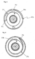
- FIG. 2 is a cross-sectional view taken along line II-II of FIG. 1 showing a detailed fitting structure of the plate member 20.
- FIG. 3 is a perspective view showing the fitted plate member 20 of FIG. 2 .
- a first end 20a (the nearer end to the center of the ring 19 and the spool 4) is fixed to the periphery of the ring 19.
- a second end 20b (the farther end from the center of the ring 19 and the spool 4) is engaged with the internal periphery of the thick cylinder portion 4b of the spool 4. More specifically, the second end 20b penetrates the thick cylinder portion 4b from inside to outside. The second end 20b can be disengaged from the thick cylinder portion 4b (the details will be described below).
- a middle portion 20c is located between the first end 20a and the second end 20b.
- the middle portion 20c extends around the external periphery of the ring 19 in the direction of unwinding the seat belt 3 (counterclockwise in FIG. 2 ) to form an external extending segment (P1 in FIG. 2 ). Then, the middle portion 20c makes a U-turn to form a U-turn segment (P2 in FIG. 2 ) in a ring space S which is formed between the ring 19 and the thick cylinder portion 4b and whose radial thickness is A. After making a U-turn, the middle portion 20c extends along the internal periphery of the thick cylinder portion 4b in the direction of winding the seat belt 3 (clockwise in FIG. 2 ) to form an internal extending segment (P3 in FIG. 2 ). In this example, the second end 20b to which the middle portion 20c leads is located in the substantially opposite side of the center (apart 180 degrees) from the first end 20a.
- the following description relates to an operation of the retractor 1 of this embodiment.
- the seat belt 3 When the seat belt 3 is not worn, the seat belt 3 is retracted completely by the urging force of the spring means 8.
- the spool 4 rotates in the direction of unwinding the seat belt 3, and the seat belt 3 is withdrawn smoothly.
- a tongue (not shown) which is slidably fitted to the withdrawn seat belt 3 is inserted into and engaged with a buckle unit (not shown) fixed to the auto body, a portion of the seat belt'3 that is withdrawn to excess is wound around the spool 4 by the urging force of the spring means 8. In this way, the seat belt 3 is fitted to the occupant without inflicting a feeling of pressure.
- seat belt winding torque produced by the pre-tensioner 9 is transmitted to the spool 4.
- the spool 4 winds the seat belt 3 to a predetermined length to restrain the occupant quickly.
- the deceleration sensing means 6 is activated by the large deceleration occurring in the emergency, preventing the locking gear 13 from rotating in the direction of unwinding the seat belt 3. Then the pawl 11 of the locking mechanism 7 is turned to be engaged with the internal teeth 14 of the frame 2.
- the torsion bar 5 When the spool 4 rotates relative to the torsion bar 5 a fixed angle or more, the torsion bar 5 is first deformed plastically by the twist force due to the relative rotation, and collision energy is absorbed by plastic deformation resistance at this time. With this movement, the plate member 20 provided between the ring 19 rotating together with the locking base 12 and the spool 4 rotating relative to the ring 19 is deformed plastically, and wound, for example, around the ring 19 in the direction of unwinding the seat belt 3. Further collision energy is absorbed by plastic deformation resistance at this time.
- FIG. 4 shows this behavior (for convenience, the twist rotation of the torsion bar 5 is not shown).
- the external extending segment (P1) extends, and the U-turn segment (P2) is displaced in the direction of unwinding the seat belt 3.
- the segment where the largest deformation is performed is sequentially displaced in the direction of unwinding the seat belt 3.
- the internal extending segment (P3) shortens, and the angle between the first end 20a and the second end 20b decreases.
- FIG. 5 shows the further progress of the relative rotation (the twist rotation of the torsion bar 5 is not shown).
- the external extending segment (P1) extends further.
- the second end 20b is disengaged from the thick cylinder portion 4b and functions as a free end (P4).
- the U-turn segment (P2) and the internal extending segment (P3) disappear.
- both plastic deformation of the torsion bar 5 and plastic deformation of the plate member 20 function as an energy absorption mechanism (EA mechanism).
- EA mechanism energy absorption mechanism
- the entire EA load is the sum of EA load when the torsion bar 5 is twisted and deformed and EA load when the plate member 20 twines around the plate fitting member.
- FIG. 6 is a graph showing a variation of the counter load (hereinafter referred to as "EA load") generated in the EA mechanism composed of the torsion bar 5 and the plate member 20 when energy is absorbed as described above.
- the horizontal axis shows stroke (angle) of rotation of the spool 4 relative to the locking base 12.
- the value of EA load is zero when the stroke of rotation of the spool 4 relative to the locking base 12 is zero. Then, when the relative rotation described above starts and the stroke starts to increase, as described above, EA load by twist of the torsion bar 5 first increases proportionally.
- the stroke increases to be a value (point a in FIG. 6 ), as described above, plastic deformation of the plate member starts in addition to twist of the torsion bar 5.
- the entire EA load is the sum of EA load by the torsion bar 5 (shown with "NT" in FIG. 6 ) and EA load by the plate member 20 (shown with "NP" in FIG. 6 ).
- the stroke is limited by the relative rotation locking member 18. That is to say, with the rotation of the spool 4 relative to the locking base 12 in the direction of unwinding the seat belt 3, the relative rotation locking member 18 moves to the right in FIG. 1. When the relative rotation locking member 18 reaches the end of the male thread, it is prevented from moving further to the right. Therefore, the rotation is locked. The relative rotation locking member 18 stops rotating relative to the locking base 12. That is to say, the spool 4 is prevented from rotating in the direction of unwinding the seat belt 3, the seat belt 3 is not withdrawn, and the occupant is prevented from being displaced due to inertia to be protected.
- This embodiment has the following advantages.
- the energy absorption characteristics of the entire retractor 1 are easily optimized. Therefore, it is possible to meet the recent needs, to optimize the energy absorption characteristics easily according to difference in structure of vehicles, and to protect the occupant's body sufficiently. This advantage will be described in detail with reference to FIGS. 7 to 9 .
- the entire energy absorption load is the sum of energy absorption load when the torsion bar 5 is deformed plastically and energy absorption load when the plate member 20 twines around the plate fitting member.
- the energy absorption load and energy absorption period concerning the torsion bar 5 can be optimized by determining the materials, thickness, and so on of the torsion bar 5.
- the energy absorption load and energy absorption period concerning the plate member 20 can be optimized easier. The technique for that will be described step by step.
- the EA plate is directly fitted to the middle of the shaft and disposed in a limited narrow space between the shaft and spool. Therefore, it is difficult to increase the radial thickness of the ring space between the shaft and the spool.
- the first end 20a of the plate member 20 is fixed not to the torsion bar 5 but to the periphery of the ring 19 provided at one end of the torsion bar 5, and the second end 20b of the plate member 20 is engaged not with the middle of the spool 4 but with the thick cylinder portion 4b at one end of the spool 4. Therefore, the radial thickness A of the ring space S is optimized by determining the diameter of the ring 19 independently of the diameter of the torsion bar 5.
- the internal diameter of the thick cylinder portion 4b of the spool 4 may be increased or decreased.
- the curvature radius of the U-turn segment (P2) is increased (or decreased). Therefore, it is easy to increase (or decrease) the EA load.
- FIG. 7 shows an example of determining the radial thickness A of the ring space S, and comparable to FIG. 2 .
- the same reference characters will be used to designate the same portions as those in FIG. 2 , so that the description thereof will be omitted.
- the ring 19 of this example has a thin portion 19A whose radius is smaller than that of the other portion and forming a recess.
- the thin portion 19A may be provided entirely in the axial direction.
- FIG. 8 is a graph showing a variation of EA load in this case, and comparable to FIG. 6 .
- the same reference characters will be used to designate the same portions as those in FIG. 6 , so that the description thereof will be omitted.
- value of EA load is the same as in FIG. 6 (the origin 0 to point c' through point a and point b).
- the plate member 20 enters the thin portion 19A (point c') and twines around the thin portion 19A.
- the distance (A' in FIG. 7 ) between the plate member 20 and the thick cylinder portion 4b increases gradually.
- the curvature radius of the U-turn segment (P2) increases gradually.
- the EA load can be decreased gradually (the right from point c' in FIG. 8 ).
- the second end 20b is disengaged from the thick cylinder portion 4b (point d).
- the radial thickness A of the ring space S can be determined freely as described above. Therefore, it is easy to increase EA load by increasing the thickness of the plate member 20 to enhance the rigidity. It is also easy to decrease EA load by decreasing the thickness to reduce the rigidity.
- the width of the plate member 20 may be varied.
- FIG. 9 shows a plate member 20 whose width W is varied.
- the plate member 20 has a narrow portion 20A in the vicinity of the second end 20b.
- the width W' of the narrow portion 20 is smaller than the width W of the other portion.
- the width of the second end 20b is also smaller.
- strength of the plate member 20 is smaller than that of the other portion. Therefore, when the plate member 20 is deformed from the first end sequentially and twines around the ring 19 as shown in FIG. 4 , and the narrow portion 20A is deformed plastically in the late stage, the load necessary for plastic deformation is smaller than a prior one. In this way, the energy absorption load can become smaller than a prior one.
- the width W' of the narrow portion 20A decreases gradually toward the,second end 20b. Therefore, the EA load characteristics are the same as in FIG. 8 . (In this case, point c' to point d in FIG. 8 corresponds to the narrow portion 20A.)
- the engaging position of the EA plate with the spool is in the middle portion in the axial direction.
- the middle portion of the spool is for winding the webbing and provided with a webbing-fixing structure (see FIG. 6 of Japanese Patent No. 2875505 ). Therefore, the engaging position of the EA plate with the spool in the circumferential direction is limited by the webbing-fixing structure and cannot be determined freely.
- the engaging position of the plate member 20 with the spool 4 is in the thick cylinder portion 4b at the end of the spool 4. Therefore, the engaging position of the plate member 20 with the spool 4 in the circumferential direction is not limited by the webbing-fixing structure and can be determined freely. Therefore, it is possible to reduce the energy absorption period (the horizontal axis) shown in FIGS. 6 and 8 by moving the engaging position of the second end 20b of the plate member 20 counterclockwise in FIG.. 2 to decrease the stroke when the second end 20b of the plate member 20 twines around the ring 19. It is'also possible to extend the energy absorption period by moving the engaging position of the plate member 20 clockwise in FIG. 2 to increase the stroke when the plate member 20 twines around the ring 19. In this way, the EA load characteristics can be optimized.
- the EA load and energy absorption period of the retractor 1 of this embodiment are easily optimized.
- the energy absorption characteristics of the entire retractor 1 is easily optimized. Therefore, it is possible to meet the recent needs, to optimize the energy absorption characteristics easily according to difference in structure of vehicles, and to protect the occupant's body sufficiently.
- the second end 20b of the plate member 20 is disengaged from the thick cylinder portion 4b in the late stage of collision. Then, collision energy absorption by the plate member 20 stops. Therefore, after that, it is possible to make the torsion bar 5 alone absorb the energy as shown in FIG. 6 . Consequently, in addition to the effect described in (1) above, the collision energy absorption load and energy absorption period of the entire retractor 1 can be determined more freely and optimized flexibly.
- the thick cylinder portion 4b of the spool 4 may be provided with a projection 30 projecting from the internal surface, and the second end 20b of the plate member 20 may be in contact with the projection 30.
- the second end 20b of the plate member 20 is not L-shape as in the above-mentioned examples but straight.
- the projection 30 has an end face 30a with which the second end 20b is in contact on one side in the circumferential direction (the left side in FIG. 10 , that is to say, the side in the direction of rotation of the spool 4 relative to the torsion bar 5).
- the second end 20b When the relative rotation starts, the second end 20b is biased by the surface 30a in the direction of the relative rotation, and the plate member 20 is deformed and wound around the ring 19 in the direction of unwinding the seat belt'3 as described with reference to FIG. 4 . According to further progress of the relative rotation, the second end 20b is separated from the surface 30a to be separated from the thick cylinder portion 4b.
- Such a structure enables the plate member 20 to be separated from the thick cylinder portion 4b more smoothly and enables the plate member 20 to stop absorbing the collision energy compared with the case shown in FIG. 2 , in which the second end 20b of the plate member 20 is L-shape and penetrates the thick cylinder portion 4b from inside to outside.
- the recent vehicles are equipped with an SRS (Supplemental Restraint System) airbag system which is inflated in an emergency, cushions the occupant, and thus protects the occupant's body.
- SRS Supplemental Restraint System
- the airbag system and the seat belt device cooperate to improve the safety of occupant.
- role is shared between the airbag system and the seat belt device to maximize the effects of the airbag system safely.
- the seat belt device ensures a large energy absorption load to minimize the displacement of the occupant.
- the seat belt device decreases the energy absorption load and leaves the airbag system to protect the occupant.
- a thick cylinder portion 4b is formed at one end of the spool 4, and a ring space S for disposing the plate member 20 is formed between the internal surface of the thick cylinder portion 4b and the periphery of the ring 19. Therefore, it is avoided to increase the diameter of the entire spool 4 to accommodate the ring 19 and the plate member 20, and the retractor 1 is compact.
Landscapes
- Engineering & Computer Science (AREA)
- Mechanical Engineering (AREA)
- Automotive Seat Belt Assembly (AREA)
Claims (7)
- Rétracteur de ceinture de sécurité comprenant :un élément rotatif sensiblement en forme de cylindre (4) pour enrouler une ceinture de sécurité (3) ;un élément formant arbre (5) prévu à l'intérieur de l'élément rotatif sensiblement en forme de cylindre (4) ;un élément d'ajustement de plaque (19) disposé à l'intérieur d'une partie d'extrémité de l'élément sensiblement en forme de cylindre et raccordé en rotation à une extrémité de l'élément formant arbre (5) conjointement avec ce dernier ;un mécanisme de verrouillage (7) empêchant l'élément formant arbre de tourner dans la direction du déroulement de la ceinture de sécurité ; etun élément de plaque (20) pouvant être plastiquement déformé, dont une extrémité est fixée à la périphérie de l'élément d'ajustement de plaque (19), et dont l'autre extrémité est mise en prise avec la surface interne de la partie d'extrémité de l'élément sensiblement en forme de cylindre (5),dans lequel l'élément sensiblement en forme de cylindre (4) à une partie de cylindre principale (4a) pour enrouler la ceinture de sécurité (3) et une partie de cylindre épaisse (4b) ayant un diamètre externe qui est supérieur à celui de la partie de cylindre principale (4a) ; etl'élément d'ajustement de plaque (19) est sensiblement en forme de disque ;caractérisé en ce qu'une première extrémité de l'élément de plaque (20) est fixée à la périphérie de l'élément d'ajustement de plaque (19) et une seconde extrémité de l'élément de plaque (20) est mise en prise avec la surface interne de la partie de cylindre épaisse (4b),dans lequel la seconde extrémité de l'élément de plaque (20) est mise en prise avec la surface interne de la partie de cylindre épaisse (4b) afin d'être dégagée de la partie de cylindre épaisse (4b) à un moment prédéterminé après que l'élément sensiblement en forme de cylindre (4) a commencé à tourner par rapport à l'élément d'ajustement de plaque (19).
- Rétracteur de ceinture de sécurité comprenant :un élément rotatif sensiblement en forme de cylindre (4) pour enrouler une ceinture de sécurité (3) ;un élément formant arbre (5) prévu à l'intérieur de l'élément sensiblement en forme de cylindre (4) ;un élément d'ajustement de plaque (19) disposé à l'intérieur d'une partie d'extrémité de l'élément sensiblement en forme de cylindre et raccordé en rotation à une extrémité de l'élément formant arbre (5) conjointement avec ce dernier ;un mécanisme de verrouillage (7) empêchant l'élément formant arbre de tourner dans la direction de déroulement de la ceinture de sécurité ; etun élément de plaque (20) pouvant être plastiquement déformé, dont une extrémité est fixée à la périphérie de l'élément d'ajustement de plaque (19), et dont l'autre extrémité est mise en prise avec la surface interne de la partie d'extrémité de l'élément sensiblement en forme de cylindre (5),dans lequel l'élément sensiblement en forme de cylindre (4) a une partie de cylindre principale (4a) pour enrouler la ceinture de sécurité (3) et une partie de cylindre épaisse (4b) ayant un diamètre externe qui est supérieur à celui de la partie de cylindre principale (4a) ;l'élément d'ajustement de plaque (19) est sensiblement en forme de disque ;caractérisé en ce qu'une première extrémité de l'élément de plaque (20) est fixée à la périphérie de l'élément d'ajustement de plaque (19), et une seconde extrémité de l'élément de plaque (20) est mise en prise avec la surface interne de la partie de cylindre épaisse (4b) ;dans lequel la partie de cylindre épaisse (4b) de l'élément sensiblement en forme de cylindre (4) a une saillie (30) faisant saillie vers l'intérieur ; etl'élément de plaque (20) est disposé de sorte que la seconde extrémité est en contact avec la saillie (30).
- Rétracteur de ceinture de sécurité selon la revendication 2,
dans lequel la saillie (30) a une face d'extrémité (30a) pour être en contact dans la direction circonférentielle ; et
l'élément de plaque (20) est disposé de sorte que la seconde extrémité est en contact avec la face d'extrémité (30a) pour le contact. - Rétracteur de ceinture de sécurité selon la revendication 2 ou 3,
dans lequel la saillie (30) a une face d'extrémité (30a) pour le contact dans la direction de rotation de l'élément sensiblement en forme de cylindre (4) par rapport à l'élément d'ajustement de plaque (19) ; et
l'élément de plaque (20) est disposé de sorte que la seconde extrémité est en contact avec la face d'extrémité (30a) pour le contact à solliciter dans la direction de rotation relative jusqu'à un moment prédéterminé après que l'élément sensiblement en forme de cylindre (4) a commencé à tourner par rapport à l'élément d'ajustement de plaque (19), et de sorte que la seconde extrémité se sépare de la face d'extrémité (30a) pour le contact après le moment prédéterminé. - Rétracteur de ceinture de sécurité selon l'une quelconque des revendications précédentes,
dans lequel l'élément formant arbre (5) est prévu à l'intérieur de l'élément sensiblement en forme de cylindre (4) de manière rotative par rapport à ce dernier,
dans lequel l'élément de plaque (20) est disposé pour être plastiquement déformé par la force de rotation transmisse lorsque l'élément sensiblement en forme de cylindre (4) et l'élément formant arbre (5) tournent l'un par rapport à l'autre,
dans lequel une extrémité de l'élément formant arbre (5) est raccordée à l'élément sensiblement en forme de cylindre (4) de sorte que l'élément en forme de cylindre (5) peut tourner conjointement avec ce dernier et être tordu et déformé, et
dans lequel l'élément d'ajustement de plaque (19) est raccordé à l'autre extrémité de l'élément formant arbre (5) afin de tourner conjointement avec ce dernier à l'intérieur d'une partie d'extrémité de l'élément sensiblement en forme de cylindre (4). - Rétracteur de ceinture de sécurité selon l'une quelconque des revendications précédentes,
dans lequel l'élément d'ajustement de plaque (19) en forme de disque a une partie fine (19a), le rayon de la partie fine étant inférieur à celui de l'autre partie, l'élément de plaque (20) se jumelant autour de la partie fine (19a) de sorte que la distance entre l'élément de plaque (20) et la partie de cylindre épaisse (4b) est plus longue que la précédente. - Rétracteur de ceinture de sécurité selon l'une quelconque des revendications précédentes,
dans lequel l'élément de plaque (20) a une partie étroite (20A) ayant une plus petite largeur que celle de l'autre partie au niveau de la seconde extrémité.
Priority Applications (1)
| Application Number | Priority Date | Filing Date | Title |
|---|---|---|---|
| EP12003335.2A EP2591956A2 (fr) | 2003-04-15 | 2004-04-15 | Rétracteur de ceinture de sécurité |
Applications Claiming Priority (6)
| Application Number | Priority Date | Filing Date | Title |
|---|---|---|---|
| JP2003110068 | 2003-04-15 | ||
| JP2003110068A JP2004314744A (ja) | 2003-04-15 | 2003-04-15 | シートベルトリトラクタおよびこれを備えたシートベルト装置 |
| JP2003283373 | 2003-07-31 | ||
| JP2003283373A JP4404335B2 (ja) | 2003-07-31 | 2003-07-31 | シートベルトのリトラクター装置及びシートベルト装置 |
| JP2003414607A JP2005170266A (ja) | 2003-12-12 | 2003-12-12 | シートベルトのリトラクター装置 |
| JP2003414607 | 2003-12-12 |
Related Child Applications (1)
| Application Number | Title | Priority Date | Filing Date |
|---|---|---|---|
| EP12003335.2 Division-Into | 2012-05-03 |
Publications (2)
| Publication Number | Publication Date |
|---|---|
| EP1468882A1 EP1468882A1 (fr) | 2004-10-20 |
| EP1468882B1 true EP1468882B1 (fr) | 2013-12-11 |
Family
ID=32912847
Family Applications (3)
| Application Number | Title | Priority Date | Filing Date |
|---|---|---|---|
| EP04008985.6A Expired - Lifetime EP1468882B1 (fr) | 2003-04-15 | 2004-04-15 | Rétracteur de ceinture de sécurité |
| EP12003335.2A Withdrawn EP2591956A2 (fr) | 2003-04-15 | 2004-04-15 | Rétracteur de ceinture de sécurité |
| EP04008987A Withdrawn EP1468883A1 (fr) | 2003-04-15 | 2004-04-15 | Rétracteur de ceinture de sécurité |
Family Applications After (2)
| Application Number | Title | Priority Date | Filing Date |
|---|---|---|---|
| EP12003335.2A Withdrawn EP2591956A2 (fr) | 2003-04-15 | 2004-04-15 | Rétracteur de ceinture de sécurité |
| EP04008987A Withdrawn EP1468883A1 (fr) | 2003-04-15 | 2004-04-15 | Rétracteur de ceinture de sécurité |
Country Status (3)
| Country | Link |
|---|---|
| US (1) | US7152824B2 (fr) |
| EP (3) | EP1468882B1 (fr) |
| CN (1) | CN100534837C (fr) |
Families Citing this family (37)
| Publication number | Priority date | Publication date | Assignee | Title |
|---|---|---|---|---|
| US7392957B2 (en) | 2003-04-15 | 2008-07-01 | Takata Corporation | Seatbelt retractor system and seatbelt system |
| DE602004009303T2 (de) | 2004-07-20 | 2008-07-10 | Key Safety Systems, Inc., Sterling Heights | Gurtaufroller |
| US20060022078A1 (en) * | 2004-07-28 | 2006-02-02 | Takata Corporation | Seatbelt retractor and seatbelt system |
| US7370822B2 (en) * | 2004-07-28 | 2008-05-13 | Takata Corporation | Seatbelt retractor having multi-level load-limit setting devices |
| JP4632302B2 (ja) * | 2005-03-22 | 2011-02-16 | タカタ株式会社 | シートベルトリトラクタおよびこれを備えたシートベルト装置 |
| JP2006306142A (ja) * | 2005-04-26 | 2006-11-09 | Takata Corp | シートベルトリトラクタおよびこれを備えているシートベルト装置 |
| DE102005026885B4 (de) * | 2005-06-10 | 2015-01-08 | Trw Automotive Gmbh | Kraftbegrenzer für einen Fahrzeug-Sicherheitsgurt |
| US20070120000A1 (en) * | 2005-11-30 | 2007-05-31 | Takata Seat Belts, Inc. | Seat belt retractor including an energy absorbing device |
| JP5078110B2 (ja) * | 2006-06-15 | 2012-11-21 | タカタ株式会社 | シートベルトリトラクタおよびこれを備えているシートベルト装置 |
| DE102008007110B3 (de) * | 2008-01-31 | 2009-02-12 | Autoliv Development Ab | Selbstsperrender Gurtaufroller |
| JP5014313B2 (ja) * | 2008-11-07 | 2012-08-29 | タカタ株式会社 | シートベルトのリトラクター装置及びシートベルト装置 |
| EP2360069B1 (fr) * | 2008-12-16 | 2013-03-20 | Autoliv Development AB | Dispositif de ceinture de sécurité |
| US20100213302A1 (en) * | 2009-02-26 | 2010-08-26 | Tk Holdings Inc. | Retractor assembly |
| US8006927B2 (en) * | 2009-05-29 | 2011-08-30 | Honda Motor Co., Ltd. | Attenuated seatbelt stopper |
| JP5455597B2 (ja) | 2009-12-15 | 2014-03-26 | タカタ株式会社 | シートベルトリトラクタおよびこれを備えたシートベルト装置 |
| US20120175937A1 (en) * | 2011-01-10 | 2012-07-12 | GM Global Technology Operations LLC | Seat belt retractor and pretensioner |
| JP2013035444A (ja) | 2011-08-09 | 2013-02-21 | Takata Corp | シートベルトのリトラクタ装置及びシートベルト装置 |
| US10046062B2 (en) * | 2011-10-21 | 2018-08-14 | Joyson Safety Systems Acquisition Llc | Retractor |
| WO2013074975A1 (fr) * | 2011-11-18 | 2013-05-23 | Tk Holdings Inc. | Rétracteur de ceinture de sécurité |
| DE102011087413A1 (de) * | 2011-11-30 | 2013-06-06 | Autoliv Development Ab | Gurtaufroller mit zwei parallel wirkenden Kraftbegrenzungseinrichtungen |
| JP5843651B2 (ja) * | 2012-02-17 | 2016-01-13 | タカタ株式会社 | シートベルトリトラクタおよびこれを備えているシートベルト装置 |
| JP2013184605A (ja) * | 2012-03-08 | 2013-09-19 | Tokai Rika Co Ltd | ウェビング巻取装置 |
| JP6026162B2 (ja) | 2012-07-13 | 2016-11-16 | 芦森工業株式会社 | シートベルト用リトラクタ |
| CN103847684B (zh) * | 2012-11-29 | 2016-06-29 | 上海和励信息科技有限公司 | 用于安全带卷收器的扭力杆、安全带卷收器及安全带总成 |
| JP6126986B2 (ja) * | 2013-12-24 | 2017-05-10 | 株式会社東海理化電機製作所 | ウェビング巻取装置 |
| DE102014210397B4 (de) * | 2014-06-03 | 2018-01-11 | Autoliv Development Ab | Gurtaufroller für eine Sicherheitsgurteinrichtung eines Kraftfahrzeugs mit einer rotatorischen Straffvorrichtung und einer Kraftbegrenzungseinrichtung |
| DE102014211979B3 (de) * | 2014-06-23 | 2015-08-20 | Autoliv Development Ab | Gurtaufroller mit einer Kraftbegrenzungseinrichtung |
| US10040419B2 (en) * | 2015-05-27 | 2018-08-07 | Kabushiki Kaisha Tokai-Rika-Denki-Seisakusho | Webbing take-up device |
| JP2017081187A (ja) * | 2015-10-22 | 2017-05-18 | 株式会社東海理化電機製作所 | ウェビング巻取装置 |
| CN107226061A (zh) * | 2016-03-23 | 2017-10-03 | 天合汽车科技(上海)有限公司 | 具有限力装置的安全带卷收器和具有安全带卷收器的车辆 |
| US9744940B1 (en) * | 2016-04-13 | 2017-08-29 | Autoliv Asp, Inc. | Seatbelt pretensioning retractor assembly |
| US11180111B2 (en) * | 2019-03-29 | 2021-11-23 | Ford Global Technologies, Llc | Seatbelt retractor assembly |
| CN110304564B (zh) * | 2019-07-01 | 2021-06-01 | 张爱伦 | 用于飞行器的货物收放装置 |
| US11577686B2 (en) * | 2020-01-22 | 2023-02-14 | Ford Global Technologies, Llc | Load-limiting seatbelt retractor |
| JP2022069979A (ja) * | 2020-10-26 | 2022-05-12 | 芦森工業株式会社 | シートベルト用リトラクタ |
| US20250136039A1 (en) * | 2023-10-27 | 2025-05-01 | ZF Passive Safety Systems US Inc. | Seatbelt retractor |
| US20260061963A1 (en) * | 2024-08-27 | 2026-03-05 | ZF Passive Safety Systems US Inc. | Seatbelt retractor |
Family Cites Families (16)
| Publication number | Priority date | Publication date | Assignee | Title |
|---|---|---|---|---|
| US66817A (en) * | 1867-07-16 | Sachusetts | ||
| US8262A (en) * | 1851-07-29 | Knitting-machine | ||
| US192978A (en) * | 1877-07-10 | Improvement in bale-ties | ||
| GB1335807A (en) | 1972-03-30 | 1973-10-31 | Ford Motor Co | Energy absorbing reel for a motor vehicle seat belt assembly |
| JP2875505B2 (ja) | 1995-10-16 | 1999-03-31 | 株式会社東海理化電機製作所 | ウエビング巻取装置 |
| DE69722972T2 (de) | 1996-01-24 | 2004-05-13 | Breed Automotive Technology, Inc., Lakeland | Sicherheitsgurtaufroller |
| JP3709231B2 (ja) | 1996-01-24 | 2005-10-26 | 株式会社東海理化電機製作所 | ウエビング巻取装置 |
| DE29816280U1 (de) | 1998-09-10 | 1999-01-21 | TRW Occupant Restraint Systems GmbH & Co. KG, 73553 Alfdorf | Vorrichtung zur Kraftbegrenzung |
| DE29922561U1 (de) | 1999-12-22 | 2000-05-04 | TRW Occupant Restraint Systems GmbH & Co. KG, 73553 Alfdorf | Kraftbegrenzer für Gurtaufroller |
| JP3723423B2 (ja) | 2000-05-31 | 2005-12-07 | エヌエスケー・オートリブ株式会社 | シートベルト装置 |
| DE20110423U1 (de) | 2000-06-29 | 2001-10-11 | Autoliv Development AB, Vårgårda | Gurtaufroller mit zweifach wirkender Kraftbegrenzungseinrichtung |
| JP3754283B2 (ja) | 2000-08-15 | 2006-03-08 | 株式会社東海理化電機製作所 | ウエビング巻取装置 |
| JP4721387B2 (ja) | 2000-12-08 | 2011-07-13 | タカタ株式会社 | シートベルトリトラクタ |
| JP2003019945A (ja) | 2001-07-09 | 2003-01-21 | Nsk Autoliv Co Ltd | シートベルト装置 |
| GB2387575B (en) | 2002-04-16 | 2004-04-14 | Breed Automotive Tech | Retractor |
| JP2004231019A (ja) | 2003-01-29 | 2004-08-19 | Nsk Autoliv Co Ltd | シートベルト用リトラクタ |
-
2004
- 2004-04-02 US US10/815,935 patent/US7152824B2/en not_active Expired - Lifetime
- 2004-04-15 CN CNB200410034843XA patent/CN100534837C/zh not_active Expired - Fee Related
- 2004-04-15 EP EP04008985.6A patent/EP1468882B1/fr not_active Expired - Lifetime
- 2004-04-15 EP EP12003335.2A patent/EP2591956A2/fr not_active Withdrawn
- 2004-04-15 EP EP04008987A patent/EP1468883A1/fr not_active Withdrawn
Also Published As
| Publication number | Publication date |
|---|---|
| EP1468882A1 (fr) | 2004-10-20 |
| US7152824B2 (en) | 2006-12-26 |
| US20040206844A1 (en) | 2004-10-21 |
| EP1468883A1 (fr) | 2004-10-20 |
| EP2591956A2 (fr) | 2013-05-15 |
| CN100534837C (zh) | 2009-09-02 |
| CN1537755A (zh) | 2004-10-20 |
Similar Documents
| Publication | Publication Date | Title |
|---|---|---|
| EP1468882B1 (fr) | Rétracteur de ceinture de sécurité | |
| EP1550589B1 (fr) | Enrouleur de ceinture | |
| US5626306A (en) | Multiple level load limiter for primary and secondary collisions | |
| GB2387575A (en) | Seat belt retractor with force limiting wire | |
| JP4662214B2 (ja) | シートベルトリトラクタ | |
| US6578786B2 (en) | Seat belt retractor with load absorbing mechanism | |
| US8403423B2 (en) | Method of limiting a load applied on a seat belt in an emergency | |
| US7878439B2 (en) | Retractor with pretensioner for auxiliary load limitation | |
| WO2013021787A1 (fr) | Dispositif d'enrouleur pour ceinture de sécurité, et dispositif de ceinture de sécurité | |
| EP2184210B1 (fr) | Rétracteur de ceinture de sécurité et appareil de ceinture de sécurité | |
| US9079565B2 (en) | Progressive load limiting restraint system | |
| US7392957B2 (en) | Seatbelt retractor system and seatbelt system | |
| US20060237572A1 (en) | Seatbelt retractor | |
| EP1975016B1 (fr) | Rétracteur de ceinture de sécurité et son appareil de ceinture de sécurité | |
| US20050098997A1 (en) | Seatbelt retractor and seatbealt device | |
| US6863234B2 (en) | Seatbelt retractor | |
| US20060237569A1 (en) | Seatbelt retractor | |
| JP4404335B2 (ja) | シートベルトのリトラクター装置及びシートベルト装置 | |
| JP4859131B2 (ja) | シートベルトリトラクタおよびこれを備えたシートベルト装置 | |
| JP4357721B2 (ja) | シートベルト装置 | |
| US8231073B2 (en) | Load limiting seat belt retractor | |
| JP2006341711A (ja) | シートベルトのリトラクター装置及びシートベルト装置 | |
| JP2005170266A (ja) | シートベルトのリトラクター装置 | |
| JP2004231019A (ja) | シートベルト用リトラクタ | |
| JP2002347573A (ja) | シートベルト装置 |
Legal Events
| Date | Code | Title | Description |
|---|---|---|---|
| PUAI | Public reference made under article 153(3) epc to a published international application that has entered the european phase |
Free format text: ORIGINAL CODE: 0009012 |
|
| AK | Designated contracting states |
Kind code of ref document: A1 Designated state(s): AT BE BG CH CY CZ DE DK EE ES FI FR GB GR HU IE IT LI LU MC NL PL PT RO SE SI SK TR |
|
| AX | Request for extension of the european patent |
Extension state: AL HR LT LV MK |
|
| 17P | Request for examination filed |
Effective date: 20050413 |
|
| AKX | Designation fees paid |
Designated state(s): DE FR GB SE |
|
| 17Q | First examination report despatched |
Effective date: 20100503 |
|
| GRAP | Despatch of communication of intention to grant a patent |
Free format text: ORIGINAL CODE: EPIDOSNIGR1 |
|
| INTG | Intention to grant announced |
Effective date: 20130710 |
|
| RIN1 | Information on inventor provided before grant (corrected) |
Inventor name: HIRAMATSU, KOJI |
|
| GRAS | Grant fee paid |
Free format text: ORIGINAL CODE: EPIDOSNIGR3 |
|
| GRAA | (expected) grant |
Free format text: ORIGINAL CODE: 0009210 |
|
| AK | Designated contracting states |
Kind code of ref document: B1 Designated state(s): DE FR GB SE |
|
| REG | Reference to a national code |
Ref country code: GB Ref legal event code: FG4D |
|
| REG | Reference to a national code |
Ref country code: DE Ref legal event code: R096 Ref document number: 602004043965 Country of ref document: DE Effective date: 20140206 |
|
| PG25 | Lapsed in a contracting state [announced via postgrant information from national office to epo] |
Ref country code: SE Free format text: LAPSE BECAUSE OF FAILURE TO SUBMIT A TRANSLATION OF THE DESCRIPTION OR TO PAY THE FEE WITHIN THE PRESCRIBED TIME-LIMIT Effective date: 20131211 |
|
| REG | Reference to a national code |
Ref country code: DE Ref legal event code: R097 Ref document number: 602004043965 Country of ref document: DE |
|
| PLBE | No opposition filed within time limit |
Free format text: ORIGINAL CODE: 0009261 |
|
| STAA | Information on the status of an ep patent application or granted ep patent |
Free format text: STATUS: NO OPPOSITION FILED WITHIN TIME LIMIT |
|
| 26N | No opposition filed |
Effective date: 20140912 |
|
| GBPC | Gb: european patent ceased through non-payment of renewal fee |
Effective date: 20140415 |
|
| REG | Reference to a national code |
Ref country code: DE Ref legal event code: R097 Ref document number: 602004043965 Country of ref document: DE Effective date: 20140912 |
|
| REG | Reference to a national code |
Ref country code: FR Ref legal event code: ST Effective date: 20141231 |
|
| PG25 | Lapsed in a contracting state [announced via postgrant information from national office to epo] |
Ref country code: GB Free format text: LAPSE BECAUSE OF NON-PAYMENT OF DUE FEES Effective date: 20140415 |
|
| PG25 | Lapsed in a contracting state [announced via postgrant information from national office to epo] |
Ref country code: FR Free format text: LAPSE BECAUSE OF NON-PAYMENT OF DUE FEES Effective date: 20140430 |
|
| REG | Reference to a national code |
Ref country code: DE Ref legal event code: R082 Ref document number: 602004043965 Country of ref document: DE Representative=s name: KRAUS & WEISERT PATENTANWAELTE PARTGMBB, DE Ref country code: DE Ref legal event code: R081 Ref document number: 602004043965 Country of ref document: DE Owner name: JOYSON SAFETY SYSTEMS JAPAN K.K., JP Free format text: FORMER OWNER: TAKATA CORP., TOKIO/TOKYO, JP |
|
| PGFP | Annual fee paid to national office [announced via postgrant information from national office to epo] |
Ref country code: DE Payment date: 20180420 Year of fee payment: 15 |
|
| REG | Reference to a national code |
Ref country code: DE Ref legal event code: R119 Ref document number: 602004043965 Country of ref document: DE |
|
| PG25 | Lapsed in a contracting state [announced via postgrant information from national office to epo] |
Ref country code: DE Free format text: LAPSE BECAUSE OF NON-PAYMENT OF DUE FEES Effective date: 20191101 |