EP1468902A2 - Clip device for the assembly of a bike fender to a support staff - Google Patents
Clip device for the assembly of a bike fender to a support staff Download PDFInfo
- Publication number
- EP1468902A2 EP1468902A2 EP04008809A EP04008809A EP1468902A2 EP 1468902 A2 EP1468902 A2 EP 1468902A2 EP 04008809 A EP04008809 A EP 04008809A EP 04008809 A EP04008809 A EP 04008809A EP 1468902 A2 EP1468902 A2 EP 1468902A2
- Authority
- EP
- European Patent Office
- Prior art keywords
- limbs
- fender
- clip device
- support staff
- assembly
- Prior art date
- Legal status (The legal status is an assumption and is not a legal conclusion. Google has not performed a legal analysis and makes no representation as to the accuracy of the status listed.)
- Granted
Links
Images

Classifications
-
- B—PERFORMING OPERATIONS; TRANSPORTING
- B62—LAND VEHICLES FOR TRAVELLING OTHERWISE THAN ON RAILS
- B62J—CYCLE SADDLES OR SEATS; AUXILIARY DEVICES OR ACCESSORIES SPECIALLY ADAPTED TO CYCLES AND NOT OTHERWISE PROVIDED FOR, e.g. ARTICLE CARRIERS OR CYCLE PROTECTORS
- B62J15/00—Mud-guards for wheels
- B62J15/02—Fastening means; Stays
Definitions
- the present invention refers to a clip device for the assembly of a bike fender to a support staff.
- the European Patent EP 0934870 refers to a device for the fastening of a fender to a support staff or tie rod, comprising a clip provided with two limbs connected in their lower part through a flexible tongue, closed by folding on a portion of the fender.
- the clip is characterised by comprising a longitudinal recess in which the support staff is inserted, the terminal portion of the latter coming out of the recess.
- the longitudinal recess is parallel to the clip's longitudinal axis and is produced in a staggered position with respect to this, passing to the right or left of the closing screw, according to the side of the fender, right or left, on which the device is intended to be assembled.
- a variation of the device just described is represented by a symmetrical clip contemporaneously comprising two parallel longitudinal recesses, one made to the right of the screw, the other to the left of the screw.
- the task of the present invention is to achieve a clip device for the assembly of a bicycle fender to a support staff which overcomes the drawbacks of the known, cited technique.
- One object of the finding is to achieve a clip device which may be assembled indiscriminately and unambiguously on the right or left side of the bike fender.
- Another object is to achieve a clip device which permits lower assembly and production costs.
- Still another object is to achieve a clip device which assures the safety of the cyclist in case of accident.
- a clip device for the assembly of a bike fender to a support staff comprising two limbs connected on their lower part by a hinge and closable one over the other, characterised in that one of said limbs comprises a channel of V shape for the insertion of the terminal end of said support staff into one of the branches of said V-shaped channel.
- the clip device is characterised in that it is symmetric with respect to a longitudinal axis.
- the clip device is characterised in that said branches of said channel are blind.
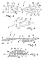
- a clip device indicated in its entirety by reference number 1, comprises two limbs 2 and 3 which may be closed by folding one over the other.
- the upper portions, respectively 2a and 3a, of the limbs 2 and 3 define, when the limbs 2 and 3 are closed one over the other, a slot 11 adapted to receive a portion of a fender 20, as may be seen in figure 6.
- the limbs 2 and 3 are closable one over the other in that they are connected on their lower part through a hinge constituted by a flexible tongue 4.
- the clip device 1 comprises a V-shaped channel 5 made in the material of one of the limbs, in this case the limb 3.
- the device 1 is symmetric with respect to its longitudinal axis 15; in particular, also the V-shaped channel 5 is symmetric with respect to the axis 15, with the vertex of the V positioned coinciding with the axis 15 and the branches 5a and 5b of the V which lead off from the vertex, diverging to the right and left of the axis 15.
- the other limb, the limb 2 comprises instead two projecting ribs 6 and 7 which have a shape complementary to that of the two branches 5a and 5b of the V-shaped channel 5.
- the opening 8 is made in the limb 3 in proximity to the flexible tongue 4, in correspondence with the vertex of the V of the channel 5.
- the branches 5a and 5b of the V-shaped channel 5 are blind, such that the support staff 30, once inserted into one of the branches 5a or 5b through the opening 8, may not come out of the clip device 1 with its end terminal.
- the upper portion 3a of the limb 3 comprises in addition a protuberance 10, of preferably hemispherical shape, projecting toward the interior of the slot 11.
- the protuberances 9 and 10 are positioned on the upper portions 2a and 3a of the limbs 2 and 3 such that, when the device 1 is in closed position with the upper parts 2a and 3a facing each other, the protuberances 9 and 10 are not aligned with respect to the vertical axis but are staggered.
- the protuberances 9 and 10 enter two housings, normally two holes, 21 and 22, made in the fender 20.
- the clip device 1 comprises the means of securing the limbs 2 and 3 one over the other in closed position, consisting of a screw 12 which may be screwed into a through hole 13 made in the clip device 1 and substantially orthogonal to the axis 15 and to the V-shaped channel 5.
- the clip device 1 is achieved in a material that is capable of being deformed, typically plastic, thereby assuring the safe release of the device 1 from the fender 20 when this last is subject to anomalous stress.
- the functioning of the finding is as follows:
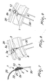
- the fender 20 of the bicycle is held in position with respect to the bicycle wheel and frame through one or more support staffs 30 (see figures 1 and 2).
- the assembly of the fender to each support staff 30 is achieved through a clip device 1.
- FIG 8 in which an enlarged view of one side of the bicycle is shown, the terminal end of a first support staff 30 is inserted into one of the branches of the V-shaped channel 5, for example the 5a branch to the right of the screw 12, passing through the opening 8.
- Figure 9 illustrates an enlarged view from the other side of the bicycle in which it is seen that the terminal end of a second support staff 30 is inserted, passing through the opening 8, into the other branch of the V-shaped channel 5, in this case to the left of the screw 12.
- the symmetry of the structure is assured, using a single clip device shape, and the operations of assembly of the fender to the support staffs prove to be rapid and immediate.
- the assembly of the fender 20 to the support staff 30 is completed by closing the limbs 2 and 3, thereby securing a portion of the fender 20 in the slot 11, with the hemispherical protuberances 8 and 9 inserted in the housings 21 and 22.
- the limbs 2 and 3 are secured in closed position by means of the screw 12.
Landscapes
- Engineering & Computer Science (AREA)
- Mechanical Engineering (AREA)
- Clamps And Clips (AREA)
- Connection Of Plates (AREA)
- Body Structure For Vehicles (AREA)
- Automobile Manufacture Line, Endless Track Vehicle, Trailer (AREA)
Abstract
Description
- The present invention refers to a clip device for the assembly of a bike fender to a support staff.
- Numerous devices for assembling a bike fender to support staffs are known, the support staffs being normally integral with the bike frame fork or wheel hub.
- The European Patent EP 0934870 refers to a device for the fastening of a fender to a support staff or tie rod, comprising a clip provided with two limbs connected in their lower part through a flexible tongue, closed by folding on a portion of the fender.
- Once the clip is assembled to the fender, said limbs are maintained in a folded-closed position through a screw fastened into a hole made in the centre of the clip and orthogonal to it.
- The clip is characterised by comprising a longitudinal recess in which the support staff is inserted, the terminal portion of the latter coming out of the recess.
- Very often, on the pointed end of the terminal portion of the support staff coming out of the clip device, a plastic cap of protective function is inserted.
- The longitudinal recess is parallel to the clip's longitudinal axis and is produced in a staggered position with respect to this, passing to the right or left of the closing screw, according to the side of the fender, right or left, on which the device is intended to be assembled.
- By consequence, to complete the assembly of the fender to the support staffs, it is necessary to provide clips with recess to the right of the screw, fixable from one side of the fender, and with clips with recess made to the left of the screw, fixable from the other side of the fender.
- This presents the drawback of having to produce two types of clips, one with recess to the right, the other with recess to the left of the screw, with consequent increase in production costs.
- To avoid this problem, a variation of the device just described is represented by a symmetrical clip contemporaneously comprising two parallel longitudinal recesses, one made to the right of the screw, the other to the left of the screw.
- This solution, while allowing lower production costs, nevertheless involves an increase of assembly time and costs such that the operator, even using a single clip form, must place greater attention and lose more time for the correct insertion of the support staff into the longitudinal recess, which will be the recess to the right or left of the screw according to the side of the fender that is being assembled.
- Another drawback of both above-described solutions is represented by the fact that the terminal end of the support staff, coming out of the device, may represent a danger for the cyclist in case of accident.
- The protective cap which is often inserted for this reason on the point of the support staff has in turn a further drawback tied to the increase of production and assembly costs of the components.
- The task of the present invention is to achieve a clip device for the assembly of a bicycle fender to a support staff which overcomes the drawbacks of the known, cited technique.
- One object of the finding is to achieve a clip device which may be assembled indiscriminately and unambiguously on the right or left side of the bike fender.
- Another object is to achieve a clip device which permits lower assembly and production costs.
- Still another object is to achieve a clip device which assures the safety of the cyclist in case of accident.
- These objects and others which will become clearer in the following description are attained by a clip device for the assembly of a bike fender to a support staff comprising two limbs connected on their lower part by a hinge and closable one over the other, characterised in that one of said limbs comprises a channel of V shape for the insertion of the terminal end of said support staff into one of the branches of said V-shaped channel.
- Appropriately, the clip device is characterised in that it is symmetric with respect to a longitudinal axis.
Advantageously, the clip device is characterised in that said branches of said channel are blind.
Further characteristics and advantages will become clearer from the description of a preferred but not exclusive embodiment of the invention, illustrated as a significant and non-limiting example in the enclosed drawings, in which: - figure 1 shows a bicycle seen from the side, with a rear fender fastened to a support staff;
- figure 2 is a partial view from the other side of the bicycle of figure 1;
- figure 3 is a plan view of a clip device according to the finding, illustrated with limbs in open position;
- figure 4 is a plan view of the clip device, illustrated with limbs in closed position;
- figure 5 is an elevation side and section view of the clip device, shown with limbs in open position;
- figure 6 is an elevation side and section view of the clip device, shown with limbs in closed position;
- figure 7 is an elevation side view of a portion of fender assembled to the support staff by way of the clip device;
- figure 8 is an enlargement of figure 1, showing in plan view a side of a portion of fender assembled to a first support staff by way of a first clip device;
- figure 9 is an enlargement of figure 2, showing in plan view the other side of the portion of the fender assembled to a second support staff by way of a second clip device.
- With reference to the cited figures, a clip device, indicated in its entirety by
reference number 1, comprises twolimbs
The upper portions, respectively 2a and 3a, of thelimbs limbs slot 11 adapted to receive a portion of afender 20, as may be seen in figure 6.
Thelimbs flexible tongue 4.
Theclip device 1 comprises a V-shaped channel 5 made in the material of one of the limbs, in this case thelimb 3.
Thedevice 1 is symmetric with respect to its longitudinal axis 15; in particular, also the V-shaped channel 5 is symmetric with respect to the axis 15, with the vertex of the V positioned coinciding with the axis 15 and thebranches
The other limb, thelimb 2, comprises instead two projectingribs branches shaped channel 5.
As may be seen in figure 6, when thelimbs ribs branches channel 5, leaving a sufficient space such that the terminal end of asupport staff 30 may be inserted, passing through the opening 8, into one of the branches, the 5a or 5b, of thechannel 5. - The opening 8 is made in the
limb 3 in proximity to theflexible tongue 4, in correspondence with the vertex of the V of thechannel 5. - The
branches shaped channel 5 are blind, such that thesupport staff 30, once inserted into one of thebranches opening 8, may not come out of theclip device 1 with its end terminal. - As may be more precisely seen in figure 6, the
upper portion 3a of thelimb 3 comprises in addition aprotuberance 10, of preferably hemispherical shape, projecting toward the interior of theslot 11. - Still in figure 6 it may be seen that, preferably but not exclusively, the
protuberances upper portions limbs device 1 is in closed position with theupper parts protuberances - Furthermore, as may be observed in figure 7, when the
device 1 is in closed position and fastened to thefender 20, theprotuberances fender 20. Theclip device 1 comprises the means of securing thelimbs screw 12 which may be screwed
into a throughhole 13 made in theclip device 1 and substantially orthogonal to the axis 15 and to the V-shaped channel 5.
The right andleft branches shaped channel 5, as illustrated in figure 3, diverge from the axis 15, passing to the right and left of thehole 13.
Theclip device 1 is achieved in a material that is capable of being deformed, typically plastic, thereby assuring the safe release of thedevice 1 from thefender 20 when this last is subject to anomalous stress.
The functioning of the finding is as follows:
Thefender 20 of the bicycle is held in position with respect to the bicycle wheel and frame through one or more support staffs 30 (see figures 1 and 2).
The assembly of the fender to eachsupport staff 30 is achieved through aclip device 1.
As may be seen in figure 8, in which an enlarged view of one side of the bicycle is shown, the terminal end of afirst support staff 30 is inserted into one of the branches of the V-shaped channel 5, for example the 5a branch to the right of thescrew 12, passing through theopening 8.
Figure 9, on the other hand, illustrates an enlarged view from the other side of the bicycle in which it is seen that the terminal end of asecond support staff 30 is inserted, passing through the opening 8, into the other branch of the V-shaped channel 5, in this case to the left of thescrew 12.
In this manner the symmetry of the structure is assured, using a single clip device shape, and the operations of assembly of the fender to the support staffs prove to be rapid and immediate.
Furthermore, it is not necessary to insert a cap on the point of thesupport staff 30 since this last does not come out of theclip device 1, the branches of the V-shaped channel 5 being blind.
The assembly of thefender 20 to thesupport staff 30 is completed by closing thelimbs fender 20 in theslot 11, with thehemispherical protuberances housings
Thelimbs screw 12.
In practice, it has been verified how the invention attains the predetermined task and the objects, having achieved a clip device for the assembly of a bicycle fender to a support staff.
The device according to the invention is susceptible to numerous modifications and variations, all included in the scope of the inventive concept; in addition, the details may be substituted by technically equivalent elements.
Naturally, any material may be used, of any dimension, according to the requirements and the state of the art.
Claims (9)
- Clip device for the assembly of a bicycle fender to a support staff comprising two limbs connected on the lower part through a hinge and closable one over the other, characterised in that one of said limbs comprises a channel of V shape for the insertion of the terminal end of said support staff into one of the branches of said V-shaped channel.
- Device, according to claim 1, characterised in that it is symmetric with respect to a longitudinal axis.
- Device, according to claim 1, characterised in that said branches of said V-shaped channel are blind.
- Device, according to one or more of the preceding claims, characterised in that when said limbs are closed one over the other, the upper portions of said limbs define a slot intended to receive a portion of said fender.
- Device, according to one or more of the preceding claims, characterised in that at least one of said upper portions of said limbs comprises a projecting protuberance adapted to fit into a corresponding housing defined on said fender portion, when said clip device is assembled to said fender portion.
- Device, according to one or more of the preceding claims, characterised in that it comprises the means to secure said limbs, in closed position, one over the other.
- Device, according to the preceding claim, characterised in that said means comprise a screw which may be screwed in a hole, passing through said limbs when these last are in closed position, one over the other, said hole being substantially orthogonal to said longitudinal axis.
- Device, according to one or more of the preceding claims, characterised in that it is made of pliable material, for example plastic.
- Device, according to one or more of the preceding claims, characterised in that it comprises one or more of the described and/or illustrated characteristics.
Applications Claiming Priority (2)
| Application Number | Priority Date | Filing Date | Title |
|---|---|---|---|
| IT000082A ITVI20030082A1 (en) | 2003-04-16 | 2003-04-16 | CLAMP DEVICE FOR ASSEMBLING A FENDER |
| ITVI20030082 | 2003-04-16 |
Publications (3)
| Publication Number | Publication Date |
|---|---|
| EP1468902A2 true EP1468902A2 (en) | 2004-10-20 |
| EP1468902A3 EP1468902A3 (en) | 2007-07-25 |
| EP1468902B1 EP1468902B1 (en) | 2010-01-27 |
Family
ID=32894208
Family Applications (1)
| Application Number | Title | Priority Date | Filing Date |
|---|---|---|---|
| EP04008809A Expired - Lifetime EP1468902B1 (en) | 2003-04-16 | 2004-04-14 | Clip device for the assembly of a bike fender to a support staff |
Country Status (4)
| Country | Link |
|---|---|
| EP (1) | EP1468902B1 (en) |
| AT (1) | ATE456504T1 (en) |
| DE (1) | DE602004025308D1 (en) |
| IT (1) | ITVI20030082A1 (en) |
Cited By (1)
| Publication number | Priority date | Publication date | Assignee | Title |
|---|---|---|---|---|
| EP1944225A3 (en) * | 2007-01-12 | 2009-11-04 | sks-metaplast SCHEFFER-KLUTE GMBH | Bicycle mudguard mounting arrangement and protective cap |
Citations (1)
| Publication number | Priority date | Publication date | Assignee | Title |
|---|---|---|---|---|
| EP0934870A2 (en) | 1998-02-04 | 1999-08-11 | Passuello, Michele | Mounting clamp for a bicycle mudguard with a support rod |
Family Cites Families (5)
| Publication number | Priority date | Publication date | Assignee | Title |
|---|---|---|---|---|
| DE29704524U1 (en) * | 1997-03-13 | 1997-05-07 | Huang, Kuei C., Shu Lin Chen, Taipeh | Fender bracket |
| IT245384Y1 (en) * | 1998-09-18 | 2002-03-20 | San Giorgio Snc Di De Poli Liv | FAST FASTENING AND RELEASING DEVICE OF THE SUPPORT RODS OF A FENDER FOR BICYCLES. |
| FR2791030B1 (en) * | 1999-03-16 | 2001-06-01 | Zefal | FIXING DEVICE FOR BIKE FENDERS |
| DE20008005U1 (en) * | 2000-05-05 | 2000-07-20 | SKS Metaplast Scheffer-Klute GmbH, 59846 Sundern | Fastening device for a mudguard |
| DE20300726U1 (en) * | 2003-01-17 | 2003-03-20 | SKS Metaplast Scheffer-Klute GmbH, 59846 Sundern | Device for attaching struts to hold a mudguard on the frame of a two-wheeler |
-
2003
- 2003-04-16 IT IT000082A patent/ITVI20030082A1/en unknown
-
2004
- 2004-04-14 AT AT04008809T patent/ATE456504T1/en not_active IP Right Cessation
- 2004-04-14 EP EP04008809A patent/EP1468902B1/en not_active Expired - Lifetime
- 2004-04-14 DE DE602004025308T patent/DE602004025308D1/en not_active Expired - Lifetime
Patent Citations (1)
| Publication number | Priority date | Publication date | Assignee | Title |
|---|---|---|---|---|
| EP0934870A2 (en) | 1998-02-04 | 1999-08-11 | Passuello, Michele | Mounting clamp for a bicycle mudguard with a support rod |
Cited By (1)
| Publication number | Priority date | Publication date | Assignee | Title |
|---|---|---|---|---|
| EP1944225A3 (en) * | 2007-01-12 | 2009-11-04 | sks-metaplast SCHEFFER-KLUTE GMBH | Bicycle mudguard mounting arrangement and protective cap |
Also Published As
| Publication number | Publication date |
|---|---|
| DE602004025308D1 (en) | 2010-03-18 |
| EP1468902A3 (en) | 2007-07-25 |
| EP1468902B1 (en) | 2010-01-27 |
| ITVI20030082A1 (en) | 2004-10-17 |
| ATE456504T1 (en) | 2010-02-15 |
Similar Documents
| Publication | Publication Date | Title |
|---|---|---|
| CN208036490U (en) | The anti-theft device of electric bicycle | |
| ES2402410T3 (en) | Articulated needle guard set, with needle cannula lock | |
| JP6282491B2 (en) | Fastening mechanism and helmet | |
| US4024738A (en) | Fastener for motorcycle driver's helmet | |
| EP1468902B1 (en) | Clip device for the assembly of a bike fender to a support staff | |
| US20130248571A1 (en) | Fastener | |
| ES2942421T3 (en) | Dividing element for dividing the interior space of a wire basket | |
| KR20110032130A (en) | A burglarproof device for bicycles | |
| ES2367906T3 (en) | INSTALLATION FOR THE SETTING OF STRAPS FOR THE RETAINING OF THE WHEEL PROTECTOR IN THE FRAME OF A BICYCLE. | |
| US8042870B2 (en) | Device for attaching motor vehicle seat covers or mats | |
| ITVI20080044U1 (en) | SHIN FOR HORSES PERFECTED | |
| US6393941B1 (en) | Toe strap receiving device for a pedal | |
| US6631927B1 (en) | Ski pole handle | |
| EP0987173A2 (en) | Device for the rapid engagement and disengagement of the stays for a bicycle mudguard | |
| ES2560411T3 (en) | Belt buckle | |
| EP2014543A1 (en) | Bicycle and lock cable | |
| GB2232568A (en) | Implement point assembly | |
| KR100919130B1 (en) | Vehicle steering wheel cover with cross ornament | |
| EP3053815A1 (en) | Improved cover for protecting a bicycle and a cyclist from rain | |
| EP1492696B1 (en) | Device for fastening a bicycle mudguard comprising two interconnected elements | |
| KR20000018704U (en) | Handle fixing structure of shopping bag | |
| CN120167356A (en) | Female component of animal identification device and corresponding accessories and animal identification method | |
| KR101172197B1 (en) | Structure for mounting of trim for supporting airbag when airbag is unfolded of vehicle | |
| ES2314726T3 (en) | FINAL HARDWARE TENSIONER PROVIDED WITH A BELT ASSEMBLY DEVICE FOR THE BELT. | |
| KR102132290B1 (en) | Door cladding for a motor vehicle |
Legal Events
| Date | Code | Title | Description |
|---|---|---|---|
| PUAI | Public reference made under article 153(3) epc to a published international application that has entered the european phase |
Free format text: ORIGINAL CODE: 0009012 |
|
| AK | Designated contracting states |
Kind code of ref document: A2 Designated state(s): AT BE BG CH CY CZ DE DK EE ES FI FR GB GR HU IE IT LI LU MC NL PL PT RO SE SI SK TR |
|
| AX | Request for extension of the european patent |
Extension state: AL HR LT LV MK |
|
| PUAL | Search report despatched |
Free format text: ORIGINAL CODE: 0009013 |
|
| AK | Designated contracting states |
Kind code of ref document: A3 Designated state(s): AT BE BG CH CY CZ DE DK EE ES FI FR GB GR HU IE IT LI LU MC NL PL PT RO SE SI SK TR |
|
| AX | Request for extension of the european patent |
Extension state: AL HR LT LV MK |
|
| 17P | Request for examination filed |
Effective date: 20080116 |
|
| AKX | Designation fees paid |
Designated state(s): AT BE BG CH CY CZ DE DK EE ES FI FR GB GR HU IE IT LI LU MC NL PL PT RO SE SI SK TR |
|
| 17Q | First examination report despatched |
Effective date: 20090403 |
|
| GRAP | Despatch of communication of intention to grant a patent |
Free format text: ORIGINAL CODE: EPIDOSNIGR1 |
|
| GRAS | Grant fee paid |
Free format text: ORIGINAL CODE: EPIDOSNIGR3 |
|
| GRAA | (expected) grant |
Free format text: ORIGINAL CODE: 0009210 |
|
| AK | Designated contracting states |
Kind code of ref document: B1 Designated state(s): AT BE BG CH CY CZ DE DK EE ES FI FR GB GR HU IE IT LI LU MC NL PL PT RO SE SI SK TR |
|
| REG | Reference to a national code |
Ref country code: GB Ref legal event code: FG4D |
|
| REG | Reference to a national code |
Ref country code: CH Ref legal event code: EP |
|
| REG | Reference to a national code |
Ref country code: IE Ref legal event code: FG4D |
|
| REF | Corresponds to: |
Ref document number: 602004025308 Country of ref document: DE Date of ref document: 20100318 Kind code of ref document: P |
|
| REG | Reference to a national code |
Ref country code: NL Ref legal event code: T3 |
|
| PG25 | Lapsed in a contracting state [announced via postgrant information from national office to epo] |
Ref country code: AT Free format text: LAPSE BECAUSE OF FAILURE TO SUBMIT A TRANSLATION OF THE DESCRIPTION OR TO PAY THE FEE WITHIN THE PRESCRIBED TIME-LIMIT Effective date: 20100127 |
|
| PG25 | Lapsed in a contracting state [announced via postgrant information from national office to epo] |
Ref country code: ES Free format text: LAPSE BECAUSE OF FAILURE TO SUBMIT A TRANSLATION OF THE DESCRIPTION OR TO PAY THE FEE WITHIN THE PRESCRIBED TIME-LIMIT Effective date: 20100508 Ref country code: PT Free format text: LAPSE BECAUSE OF FAILURE TO SUBMIT A TRANSLATION OF THE DESCRIPTION OR TO PAY THE FEE WITHIN THE PRESCRIBED TIME-LIMIT Effective date: 20100527 |
|
| PG25 | Lapsed in a contracting state [announced via postgrant information from national office to epo] |
Ref country code: PL Free format text: LAPSE BECAUSE OF FAILURE TO SUBMIT A TRANSLATION OF THE DESCRIPTION OR TO PAY THE FEE WITHIN THE PRESCRIBED TIME-LIMIT Effective date: 20100127 Ref country code: FI Free format text: LAPSE BECAUSE OF FAILURE TO SUBMIT A TRANSLATION OF THE DESCRIPTION OR TO PAY THE FEE WITHIN THE PRESCRIBED TIME-LIMIT Effective date: 20100127 Ref country code: SI Free format text: LAPSE BECAUSE OF FAILURE TO SUBMIT A TRANSLATION OF THE DESCRIPTION OR TO PAY THE FEE WITHIN THE PRESCRIBED TIME-LIMIT Effective date: 20100127 |
|
| PG25 | Lapsed in a contracting state [announced via postgrant information from national office to epo] |
Ref country code: EE Free format text: LAPSE BECAUSE OF FAILURE TO SUBMIT A TRANSLATION OF THE DESCRIPTION OR TO PAY THE FEE WITHIN THE PRESCRIBED TIME-LIMIT Effective date: 20100127 Ref country code: BE Free format text: LAPSE BECAUSE OF FAILURE TO SUBMIT A TRANSLATION OF THE DESCRIPTION OR TO PAY THE FEE WITHIN THE PRESCRIBED TIME-LIMIT Effective date: 20100127 Ref country code: CY Free format text: LAPSE BECAUSE OF FAILURE TO SUBMIT A TRANSLATION OF THE DESCRIPTION OR TO PAY THE FEE WITHIN THE PRESCRIBED TIME-LIMIT Effective date: 20100127 Ref country code: GR Free format text: LAPSE BECAUSE OF FAILURE TO SUBMIT A TRANSLATION OF THE DESCRIPTION OR TO PAY THE FEE WITHIN THE PRESCRIBED TIME-LIMIT Effective date: 20100428 Ref country code: RO Free format text: LAPSE BECAUSE OF FAILURE TO SUBMIT A TRANSLATION OF THE DESCRIPTION OR TO PAY THE FEE WITHIN THE PRESCRIBED TIME-LIMIT Effective date: 20100127 Ref country code: SE Free format text: LAPSE BECAUSE OF FAILURE TO SUBMIT A TRANSLATION OF THE DESCRIPTION OR TO PAY THE FEE WITHIN THE PRESCRIBED TIME-LIMIT Effective date: 20100127 |
|
| PG25 | Lapsed in a contracting state [announced via postgrant information from national office to epo] |
Ref country code: MC Free format text: LAPSE BECAUSE OF NON-PAYMENT OF DUE FEES Effective date: 20100430 Ref country code: BG Free format text: LAPSE BECAUSE OF FAILURE TO SUBMIT A TRANSLATION OF THE DESCRIPTION OR TO PAY THE FEE WITHIN THE PRESCRIBED TIME-LIMIT Effective date: 20100427 Ref country code: CZ Free format text: LAPSE BECAUSE OF FAILURE TO SUBMIT A TRANSLATION OF THE DESCRIPTION OR TO PAY THE FEE WITHIN THE PRESCRIBED TIME-LIMIT Effective date: 20100127 Ref country code: SK Free format text: LAPSE BECAUSE OF FAILURE TO SUBMIT A TRANSLATION OF THE DESCRIPTION OR TO PAY THE FEE WITHIN THE PRESCRIBED TIME-LIMIT Effective date: 20100127 |
|
| REG | Reference to a national code |
Ref country code: CH Ref legal event code: PL |
|
| PLBE | No opposition filed within time limit |
Free format text: ORIGINAL CODE: 0009261 |
|
| STAA | Information on the status of an ep patent application or granted ep patent |
Free format text: STATUS: NO OPPOSITION FILED WITHIN TIME LIMIT |
|
| GBPC | Gb: european patent ceased through non-payment of renewal fee |
Effective date: 20100427 |
|
| 26N | No opposition filed |
Effective date: 20101028 |
|
| PG25 | Lapsed in a contracting state [announced via postgrant information from national office to epo] |
Ref country code: IE Free format text: LAPSE BECAUSE OF NON-PAYMENT OF DUE FEES Effective date: 20100414 Ref country code: DK Free format text: LAPSE BECAUSE OF FAILURE TO SUBMIT A TRANSLATION OF THE DESCRIPTION OR TO PAY THE FEE WITHIN THE PRESCRIBED TIME-LIMIT Effective date: 20100127 |
|
| PG25 | Lapsed in a contracting state [announced via postgrant information from national office to epo] |
Ref country code: LI Free format text: LAPSE BECAUSE OF NON-PAYMENT OF DUE FEES Effective date: 20100430 Ref country code: CH Free format text: LAPSE BECAUSE OF NON-PAYMENT OF DUE FEES Effective date: 20100430 |
|
| PG25 | Lapsed in a contracting state [announced via postgrant information from national office to epo] |
Ref country code: IT Free format text: LAPSE BECAUSE OF NON-PAYMENT OF DUE FEES Effective date: 20100414 Ref country code: GB Free format text: LAPSE BECAUSE OF NON-PAYMENT OF DUE FEES Effective date: 20100427 |
|
| PGFP | Annual fee paid to national office [announced via postgrant information from national office to epo] |
Ref country code: FR Payment date: 20110517 Year of fee payment: 8 |
|
| PGRI | Patent reinstated in contracting state [announced from national office to epo] |
Ref country code: IT Effective date: 20110616 |
|
| PGFP | Annual fee paid to national office [announced via postgrant information from national office to epo] |
Ref country code: NL Payment date: 20110428 Year of fee payment: 8 |
|
| PGFP | Annual fee paid to national office [announced via postgrant information from national office to epo] |
Ref country code: IT Payment date: 20110411 Year of fee payment: 8 |
|
| PGFP | Annual fee paid to national office [announced via postgrant information from national office to epo] |
Ref country code: DE Payment date: 20110609 Year of fee payment: 8 |
|
| PG25 | Lapsed in a contracting state [announced via postgrant information from national office to epo] |
Ref country code: LU Free format text: LAPSE BECAUSE OF NON-PAYMENT OF DUE FEES Effective date: 20100414 Ref country code: HU Free format text: LAPSE BECAUSE OF FAILURE TO SUBMIT A TRANSLATION OF THE DESCRIPTION OR TO PAY THE FEE WITHIN THE PRESCRIBED TIME-LIMIT Effective date: 20100728 |
|
| PG25 | Lapsed in a contracting state [announced via postgrant information from national office to epo] |
Ref country code: TR Free format text: LAPSE BECAUSE OF FAILURE TO SUBMIT A TRANSLATION OF THE DESCRIPTION OR TO PAY THE FEE WITHIN THE PRESCRIBED TIME-LIMIT Effective date: 20100127 |
|
| REG | Reference to a national code |
Ref country code: NL Ref legal event code: V1 Effective date: 20121101 |
|
| REG | Reference to a national code |
Ref country code: FR Ref legal event code: ST Effective date: 20121228 |
|
| REG | Reference to a national code |
Ref country code: DE Ref legal event code: R119 Ref document number: 602004025308 Country of ref document: DE Effective date: 20121101 |
|
| PG25 | Lapsed in a contracting state [announced via postgrant information from national office to epo] |
Ref country code: FR Free format text: LAPSE BECAUSE OF NON-PAYMENT OF DUE FEES Effective date: 20120430 Ref country code: IT Free format text: LAPSE BECAUSE OF NON-PAYMENT OF DUE FEES Effective date: 20120414 |
|
| PG25 | Lapsed in a contracting state [announced via postgrant information from national office to epo] |
Ref country code: NL Free format text: LAPSE BECAUSE OF NON-PAYMENT OF DUE FEES Effective date: 20121101 |
|
| PG25 | Lapsed in a contracting state [announced via postgrant information from national office to epo] |
Ref country code: DE Free format text: LAPSE BECAUSE OF NON-PAYMENT OF DUE FEES Effective date: 20121101 |