EP1468903A1 - Bicyclette a enveloppe de protection - Google Patents
Bicyclette a enveloppe de protection Download PDFInfo
- Publication number
- EP1468903A1 EP1468903A1 EP02746045A EP02746045A EP1468903A1 EP 1468903 A1 EP1468903 A1 EP 1468903A1 EP 02746045 A EP02746045 A EP 02746045A EP 02746045 A EP02746045 A EP 02746045A EP 1468903 A1 EP1468903 A1 EP 1468903A1
- Authority
- EP
- European Patent Office
- Prior art keywords
- cover structure
- cover
- man
- vehicle equipped
- driven vehicle
- Prior art date
- Legal status (The legal status is an assumption and is not a legal conclusion. Google has not performed a legal analysis and makes no representation as to the accuracy of the status listed.)
- Withdrawn
Links
- 229920003002 synthetic resin Polymers 0.000 claims description 17
- 239000000057 synthetic resin Substances 0.000 claims description 17
- 238000012856 packing Methods 0.000 claims description 6
- 229920003051 synthetic elastomer Polymers 0.000 claims description 4
- 239000005061 synthetic rubber Substances 0.000 claims description 4
- 230000002411 adverse Effects 0.000 abstract description 9
- 238000010586 diagram Methods 0.000 description 13
- XLYOFNOQVPJJNP-UHFFFAOYSA-N water Substances O XLYOFNOQVPJJNP-UHFFFAOYSA-N 0.000 description 12
- 238000012423 maintenance Methods 0.000 description 11
- 241000238631 Hexapoda Species 0.000 description 9
- 230000007613 environmental effect Effects 0.000 description 6
- 239000000463 material Substances 0.000 description 4
- 239000002990 reinforced plastic Substances 0.000 description 4
- 208000019901 Anxiety disease Diseases 0.000 description 3
- 230000000630 rising effect Effects 0.000 description 3
- 230000005855 radiation Effects 0.000 description 2
- 230000003014 reinforcing effect Effects 0.000 description 2
- 238000010521 absorption reaction Methods 0.000 description 1
- 230000036506 anxiety Effects 0.000 description 1
- 238000003287 bathing Methods 0.000 description 1
- 238000007664 blowing Methods 0.000 description 1
- 239000011248 coating agent Substances 0.000 description 1
- 238000000576 coating method Methods 0.000 description 1
- 238000010276 construction Methods 0.000 description 1
- 239000000428 dust Substances 0.000 description 1
- 230000005611 electricity Effects 0.000 description 1
- 238000007789 sealing Methods 0.000 description 1
Images


Classifications
-
- B—PERFORMING OPERATIONS; TRANSPORTING
- B62—LAND VEHICLES FOR TRAVELLING OTHERWISE THAN ON RAILS
- B62J—CYCLE SADDLES OR SEATS; AUXILIARY DEVICES OR ACCESSORIES SPECIALLY ADAPTED TO CYCLES AND NOT OTHERWISE PROVIDED FOR, e.g. ARTICLE CARRIERS OR CYCLE PROTECTORS
- B62J17/00—Weather guards for riders; Fairings or stream-lining parts not otherwise provided for
- B62J17/08—Hoods protecting the rider
-
- B—PERFORMING OPERATIONS; TRANSPORTING
- B62—LAND VEHICLES FOR TRAVELLING OTHERWISE THAN ON RAILS
- B62J—CYCLE SADDLES OR SEATS; AUXILIARY DEVICES OR ACCESSORIES SPECIALLY ADAPTED TO CYCLES AND NOT OTHERWISE PROVIDED FOR, e.g. ARTICLE CARRIERS OR CYCLE PROTECTORS
- B62J23/00—Other protectors specially adapted for cycles
Definitions
- the present invention relates to a man-driven vehicle equipped with a capsule-like cover structure.
- the man-driven vehicle equipped with a hood for weather protection means is well known, for example, from Japanese Laid-Open Patent Application Gazette No. 1999-59553 disclosing a man-driven vehicle having a hood extending merely above a driver or from Japanese Laid-Open Patent Application Gazette No. 1975-41243 disclosing a man-driven vehicle having a hood detachably provided so as to extend merely above a driver.
- the cover structure adapted to cover the driver from above has another inconvenience that the driver must attach and detach such cover structure to the vehicle every time the driver gets on and off the vehicle.
- the present invention provides also the man-driven vehicle equipped with the cover structure according to Claim 2 or 3 wherein said door is adapted to be opened and closed in slide mode, as described in Claim 4.
- the door can be opened or closed by means of a relatively simple hinge mechanism.
- the slide door hinge-connected to the slide member of the cover structure is pivoted around the hinge members as the door is closed, so the door is retracted within the cover structure and a width of the vehicle during its running may be correspondingly reduced.
- the present invention provides also the man-driven vehicle equipped with the cover structure according to Claim 19 wherein the cover structure is integrally mounted on the vehicle itself and the rotatable cover is rotatable relatively to the cover structure, as described in Claim 20.
- the present invention provides the man-driven vehicle equipped with the cover structure according to Claim 25, wherein the slide cover structure is provided on the rear half of a stationary cover structure, as described in Claim 26.
- the slide cover section lying on the rear part of the stationary cover may be slidably moved to enable the rotatable cover as well as the slide cover section to be opened or closed without any problem in driving of the vehicle
- the present invention provides also the man-driven vehicle equipped with the cover structure according to Claim 25 or 26, wherein one of the slide cover structure and the stationary cover structure is provided with slide rails and the other is provided with guide rollers adapted to slide along these guide rails, as described in Claim 27.
- the present invention provides also the man-driven vehicle equipped with the cover structure according to Claim 27, wherein the slide rails are provided on ends thereof with stoppers, as described in Claim 28.
- the slide cover section can be stopped at the slide terminating ends or at position along the way by said stopper means.
- the present invention provides also the man-driven vehicle equipped with the cover structure according to any one of Claims 25 through 28, wherein the slide cover structure is detachably mounted on the stationary cover structure, as described in Claim 29.
- the present invention provides also the man-driven vehicle equipped with the cover structure according to any one of Claims 18 through 30, wherein said rotatable cover comprises a plurality of rotatable cover sections, as described in Claim 31.
- a plurality of rotatable cover sections facilitate a rotation angle as well as an opened area of the rotatable cover to be adjusted and these sections may be overlapped one upon another to enlarge the opened area.
- the present invention provides also the man-driven vehicle equipped with the cover structure according to Claim 31, wherein said rotatable cover comprises an upper rotatable cover section, an intermediate rotatable cover section overlapping said upper rotatable cover section, and a lower rotatable cover section overlapping said intermediate rotatable cover section, as described in Claim 32.
- the present invention provides also the man-driven vehicle equipped with the cover structure according to Claim 31 or 32, wherein said cover structure has a shaft by which said upper rotatable cover section, intermediate rotatable cover section and lower rotatable cover section are rotatably supported, as described in Claim 33.
- the rotatable cover can be stored into a relatively small space provided on the rear part of the stationary cover as the rotatable cover is opened.
- the upper rotatable cover section may be held by the hand and fanned out to fan out successively the intermediate cover section and the lower rotatable cover section.
- the upper rotatable cover section may be held by the hand and fan-folded to fanfold successively the intermediate cover section and the lower rotatable cover section.
- the present invention provides also the man-driven vehicle equipped with the cover structure according to any one of Claims 31 through 36, wherein said interlocking projections are provided with packing members, as described in Claim 37.
- the packing members provided on the respective interlocking projections improve sealing performance of respective joints, buffer collision among the interlocking projections occurring when the respective rotatable cover sections are interlocked one with another, and stop the rotatable cover sections at desired opened positions by a frictional resistance when the packing members between respective pairs of the adjacent rotatable cover sections.
- the present invention provides also the man-driven vehicle equipped with the cover structure according to any one of Claims 1 through 37, wherein the cover structure is provided along its bottom with a ground contacting skirt, as described in Claim 38.
- the cover structure practically covering a whole of the vehicle well protects the driver from adverse environmental conditions such as rain, wind and UV (sunlight) and the flexible ground contacting skirt provided along the bottom of the cover structure protects the driver from muddy water, sandblast, insects, rain, wind, snow, chill and warmth which otherwise would enter the cover structure from below the driver's feet.
- the ground contacting skirt is sufficient flexible to ensure the vehicle running without any problem even when the skirt contacts the ground.
- the present invention provides also the man-driven vehicle equipped with the cover structure according to Claim 38, wherein said ground contacting skirt extends along the entire bottom of the cover structure, as described in Claim 39.
- the ground contacting skirt extends along the entire bottom of the cover structure and reliably protects the driver against muddy water, sandblast, insects, rain, wind, snow, chill and warmth which otherwise would attach the driver's feet from every direction.
- the present invention provides the man-driven vehicle equipped with the cover structure according to Claim 38 or 39, wherein said ground contacting skirt has at least one split lying at its rear portion as viewed in the vehicle's running direction so that the skirt splits off as the skirt contacts any obstacle or the like, as described in Claim 40.
- the present invention provides also the man-driven vehicle equipped with the cover structure according to Claim 40, wherein said ground contacting skirt comprises a set of bottom sections adapted to split off one from another, as described in Claim 41.
- the set of bottom sections are adapted to split off one from another and sufficiently flexible to pass such obstacle and to ensure the vehicle to continue to run.
- the present invention provides also the man-driven vehicle equipped with the cover structure according to Claim 41, wherein another set of bottom sections are provided so as to cover the splits of the previously described set of bottom sections, as described in Claim 42.
- said another set of bottom sections cover the splits of the adj acent set of bottom sections so as to protect the driver from muddy water, sandblast, insects, wind, rain, snow, chill and warmth which otherwise would attack the driver from below his or her feet.
- the present invention provides also the man-driven vehicle equipped with the cover structure according to Claim 42, wherein said two sets of bottom sections cooperate on with another to form the overlapping bottom sections, as described in Claim 43.
- the adjacent two sets of bottom sections overlap one another and mutually cover the splits of these two sets of bottom sections.
- the present invention provides also the man-driven vehicle equipped with the cover structure according to any one of Claims 38 through 43, wherein said ground contacting skirt is detachably mounted on the bottom of the cover structure, as described in Claim 44.
- the ground contacting skirt can be detachably attached to the bottom of the cover structure.
- the present invention provides also the man-driven vehicle equipped with the cover structure according to any one of Claims 41 through 43, wherein said plurality of bottom sections are detachably mounted one by one on the bottom of the cover structure, as described in Claim 45.
- the bottom sections can be detachably attached one by one to the bottom of the cover structure.
- the present invention provides also the man-driven vehicle equipped with the cover structure according to any one of Claims 38 through 45, wherein said ground contacting skirt comprises elastically deformable member made of synthetic rubber or synthetic resin, as described in Claim 46.
- the ground contacting skirt made of elastically deformable material such as synthetic rubber or synthetic resin is readily deformed even if the skirt comes in contact with any obstacle so as to pass such obstacle and can be detachably mounted on the cover structure without any loss of its elastic deformability.
- the present invention provides also the man-driven vehicle equipped with the cover structure according to any one of Claims 1 through 46, wherein the vehicle body is provided with a floor panel, as described in Claim 47.
- the floor panel mounted on the vehicle body effectively protect the driver against muddy water, wind and rain which otherwise would attack the driver from below his or her feet.
- the present invention provides also the man-driven vehicle equipped with the cover structure and the floor panel according to Claim 47, wherein the floor panel is provided with openings for feet setting on the ground, as described in Claim 48.
- the driver can set his or her feet on the ground through the openings provided in the floor panel for this purpose and thereby controllably brake, support or move the vehicle without rising from the seat.
- the openings for feet setting on the ground can be covered or uncovered, if necessary, by operating the openable and closable floor panel section to block adverse weather or to control the vehicle with the driver's feet set on the ground.
- the present invention provides also the man-driven vehicle equipped with the cover structure and the floor panel according to Claim 49, wherein the openable and closable panel section comprise a slidable floor panel section, as described in Claim 50.
- the floor panel section may be slid to uncover the openings for feet setting on the ground.
- the openable and closable floor panel section may be trampled down to open this floor panel section in hinge mode until the free end of this floor panel section comes in contact with the ground and thereby to control the vehicle by the free end so as to be braked or supported.
- the present invention provides also the man-driven vehicle equipped with the cover structure and the floor panel according to Claim 51, wherein the hinged floor panel section having edges adapted to be in contact with the ground and to brake the vehicle as the hinged floor panel section is opened, as described in Claim 52.
- the present invention provides also the man-driven vehicle equipped with the cover structure and the floor panel according to any one of Claims 47 through 52, wherein the floor panel extends below the pedals, as described in Claim 53.
- the driver can work the foot pedals above the floor panel and thereby reliably protect his or her feet from adverse weather.
- the present invention provides also the man-driven vehicle equipped with the cover structure and the floor panel according to any one of Claims 47 through 54, wherein the cover structure is provided integrally with the floor panel and extends above the floor panel so as to cover substantially whole of the driver, as described in Claim 55.
- the cover structure substantially covering a whole of the vehicle and the driver allows the driver to be protected from undesirable environmental conditions such as rainfall, cold wind, sandblast and to drive the vehicle without any problem.
- the present invention provides also the man-driven vehicle equipped with the cover structure according to any one of Claims 1 through 55, wherein the cover structure is provided with a solar battery, as described in Claim 56.
- the solar cell provided on the ceiling of the cover structure generates electricity used to energize various lights or to charge an accumulator.
- the present invention provides also the man-driven vehicle equipped with the cover structure according to any one of Claims 1 through 56, wherein the cover structure is provided with a front light so that the vehicle can be driven in the night, as described in Claim 57.
- the present invention provides also the man-driven vehicle equipped with the cover structure according to any one of Claims 1 through 57, wherein the front window of the cover structure is provided with a wiper so that the vehicle can be driven in the rain, as described in Claim 58.
- the present invention provides also the man-driven vehicle equipped with the cover structure according to any one of Claims 1 through 58, wherein the cover structure is provided on its rear side with a tail light so that the other vehicles approaching from behind can perceive the present of the vehicle, as described in Claim 59.
- the present invention provides also the man-driven vehicle equipped with the cover structure according to any one of Claims 1 through 59, wherein the vehicle itself has three or more wheels, as described in Claim 60.
- the vehicle can stably run without any anxiety that the vehicle might upset so far as the vehicle has three or more wheels.
- the present invention provides also the man-driven vehicle equipped with the cover structure according to any one of Claims 1 through 60, wherein the vehicle itself or the detachable cover structure or the cover structure mounting frame is provided with a battery adapted to be charged as the vehicle runs, as described in Claim 61.
- the accumulator can be charged as the vehicle runs and such accumulator can be selectively mounted on the vehicle itself, the detachable cover or the cover mounting frame.
- the present invention provides also the man-driven vehicle equipped with the cover structure according to any one of Claims 1 through 61, wherein the vehicle itself or the cover structure or the cover structure mounting frame is provided with a stationary stand adapted for rotatably supporting the wheels which are rotated as the pedals are worked, as described in Claim 62.
- the wheels supported by the stationary stand may be rotated by foot pedal working for health maintenance.
- the stationary stand may be mounted on the vehicle itself, the cover structure or the cover mounting frame.
- the present invention provides also the man-driven vehicle equipped with the cover structure according to any one of Claims 1 through 62, wherein the cover structure is provided with openable and closable windows for repairing of the vehicle, as described in Claim 63.
- the openable and closable windows provided on the cover structure may be opened when it is desired to repair the vehicle.
- the cover structure 2 may be provided with absorption ability for radiations such as UV ray to shield the radiations such as UV ray known to be harmful to human body.
- the door of hinge-slide combination type may be realized also by a pair of doors hinge-connected to each other so that the one door section is pivotally mounted on one side of the door way to be opened or closed and the other door section is opened or closed with its free end sliding along upper or lower end of the door way.
- the door is preferably constructed so as to be folded inward of the cover structure 2 and not to project outward of the cover structure 2 when the door is opened or closed.
- an openable and closable door way comprises a detachable cover structure.
- the cover structure 110 may be UV shielding material to protect human body from harmful UV.
- the cover structure may be provided with knobs, side windows, a front window, a rear window, side mirrors, wipers, head lights for running in night and a tail light having a reflecting function.
- the vehicle itself 101, the body frame 106, the detachable cover 112 or the cover mounting frame 113 may be provided with a stationary stand used to keep the vehicle stationary while the wheels are rotated by pedal working.
- a stationary stand is useful when the wheels are rotated by pedal working for health maintenance indoors with the vehicle kept stationary.
- the stationary stand may be selectively mounted on the vehicle itself, the detachable cover or the cover mounting frame.
- FIGs. 12 through 16 an embodiment of the man-driven vehicle equipped with the cover structure will be described, wherein the openable and closable door way is defined by the rotatable cover.
- the driving wheel 203 driven by the foot pedals, the intermediate wheel 205 or the driven wheel 207 is provided with the driving motor, the generator and the battery adapted to be charged by foot pedal working.It is possible to mount components such as the battery, the electric circuit and the wiring on the cover mounting frame or the stationary cover 211.
- the vehicle itself 201, the body frame, the stationary cover 211 or the cover mounting frame may be provided with a stationary stand used to keep the vehicle stationary while the wheels are rotated by pedal working.
- a stationary stand used to keep the vehicle stationary while the wheels are rotated by pedal working.
- Such stationary stand is useful when the wheels are rotated by pedal working for health maintenance indoors with the vehicle kept stationary.
- the stationary stand may be selectively mounted on the vehicle itself, the rotatable cover or the cover mounting frame.
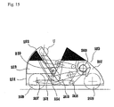
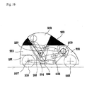
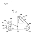
- Reference numeral 310 designates the cover structure substantially covering a whole of a vehicle itself 301 wherein a front part as well as a rear-lower part of the cover structure 310 form together a stationary cover 311 being integral with the vehicle itself 301.
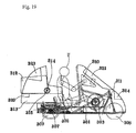
- a rear-upper part of the cover structure 310 defines a slide cover 313 adapted to slide rearward as illustrated by Fig. 19.
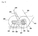
- a rotatable cover 312 is mounted on the slide cover 313 so as to be rotated integrally with a rotary shaft 314 and to be rotated by an operating knob 319.
- the rotary shaft 314 is rotatably received in a circular rotary bearing 315 integrally fixed to the slide cover 313.
- driver seat 302 driving member 303, driven member 307, and front and rear wheels 308, 309
- details of the vehicle itself 201 are not illustrated.
- a driven wheel 307 is rotated by means of a chain or the like and then the rear wheels 309 are driven.
- the vehicle itself 301 is a tricycle having a front wheel 308 for steerage and a pair of rear wheels 309.
- Reference numeral 317 designates stopper members provided on ends of the respective slide rail members 316 and adapted to come in contact with the respective guide rollers 305 at the slide limits. It is possible to provide supports for the guide rollers 305, 306 or the stopper members with means such as retractable or extensible/contractile means so that the stopper members 317 can be moved beyond the guide rollers 305, 306 and thereby the slide cover 313 can be detached from or attached to the stationary cover 311.
- the joints of the stationary cover 311, the slide cover 313 and the rotatable cover 312 may be weather-tightly sealed in projection-recess engaging mode or in overlapping mode, and there may be provided in the vicinity of these joints with detachable devices or stationary knobs by which the rotatable cover 212 is opened or closed.
- the cover structure 310 comprises a framed work made of transparent, translucent or opaque synthetic resin sheet or the like. If the structure is made of relatively flexible synthetic resin sheet or the like, the cover structure 310 is reinforced by mounting the cover structure 310 to the cover mounting frame for skeleton and integral with the vehicle 301.
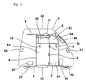
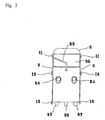
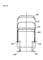
- an embodiment of the man-driven vehicle equipped with the cover structure wherein an openable and closable door way comprises a plurality of rotatable cover sections.
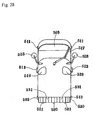
- the man-driven vehicle 401 equipped with the cover structure comprises, as shown by Fig. 22 or 23, a three- or four-wheel vehicle itself and a cover structure 405 substantially covering a whole of the vehicle itself.
- the cover structure 405 comprises a front part 402 of the cover structure provided with windows 406, 407, 408, a rear part 404 of the cover structure provided with a window 409 and a rotatable cover 403 lying between these front and rear parts and adapted to be funned out or fun-folded around a rotary shaft 415 for this cover.
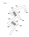
- the rotatable cover 403 comprises an upper rotatable cover section 411 having windows 410, an intermediate rotatable cover section 413 having windows 412 and adapted to overlap the inner side of the upper rotatable cover section 411 and a lower rotatable cover section 413 adapted to overlap the inner side of the intermediate rotatable cover section 414 so that the rotatable cover 403 is adapted to be fun-folded toward the rear part 404 of the cover structure around rotary shaft assembly 415.
- the interlocking means comprise interlocking projections 420, 421 extending downward from opposite ends of said upper rotatable cover section 411 as viewed in its opening and closing direction, an interlocking projection 422 extending upward from one end of said intermediate rotatable cover 413 section as viewed in its opening and closing direction, interlocking projections 423, 424 extending from the other end of said intermediate rotatable cover section 413 as viewed in its opening and closing direction and an interlocking projection 425 extending upward from one end of said lower rotatable cover section 414 as viewed in its opening and closing direction.
- the upper rotatable cover section 411 is held with the hand and rotated rearward whereupon the interlocking projection 420 comes in contact with the interlocking projection 422 so as to force the intermediate rotatable cover section 413 to be funned out and then the interlocking projection 423 comes in contact with the interlocking projection 425 so as to force the lower rotatable cover section 414 to be funned out.
- Reference numeral 430 designates a front wheel of the vehicle itself
- reference numeral 431 designates a pair of rear wheels
- reference numeral 432 designates a head light.
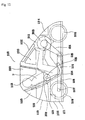
- Figs. 27 through 33 an embodiment of the man-driven vehicle equipped with the cover structure wherein the cover structure is provided along its bottom with a ground contacting skirt so that the driver can be protected from muddy water, sandblast, insects, wind, rain, snow, chill and warmth which otherwise would attach the driver from below his or her feet.
- the ground contacting skirt 530 extends along the entire bottom of the cover structure and reliably protects the driver against muddy water, sandblast, insects, rain, wind, snow, chill and warmth which otherwise would attach the driver's feet from every direction.
- the ground contacting skirt 530 can be arranged as illustrated by Fig. 32(1), in which another set of bottom sections 541 is placed on the set of bottom section 531 so that each of the bottom sections 541 may cover a split 532 between each pair of the adjacent bottom sections 531. In this way, it is possible to protect the driver from muddy water, sandblast, insects, wind, rain, snow, chill and warmth which otherwise would enter the vehicle through the splits 532 and attach the driver.
- a part or a whole of the ground contacting skirt 530 may be detachably attached to the bottom of the cover structure 502 in the conventional manner so that, if desired for example in fine weather, the skirt 530 can be removed.
- the ground contacting skirt 530 may be formed by the bottom sections made of elastically deformable synthetic rubber sheet or synthetic resin sheet to ensure that, even if the bottom sections come in contact with any obstacle, the bottom sections may readily be elastically deformed and pass such obstacle. It is easy for the bottom sections made of such elastically deformable material to be detachably attached to the cover structure.
- doors 506 on lateral sides of the cover structure 502 so that these doors 506 may be opened or closed in slide mode.
- the front of the cover structure 502 is provided with a front window 509, which is, in turn, provided with a wiper 517, and with head lights 518 used in night so as to be visible from the sides also.
- the cover structure 502 is provided on its rear side with a rear window 516 and a sufficiently wide tail light 519 to be visible from the sides also.
- the rail light 591 lies below the rear window 516 and has a reflecting function.
- the tail light 25 can be used also as a brake lamp.
- the vehicle itself 501 can be equipped with the cover structure 502 no matter whether the vehicle is two-wheeled, three-wheeled or four-wheeled vehicle so far as the vehicle itself 1 has an appropriate framework.
- the vehicle itself 501 has preferably three or more wheels in order to avoid an apprehension that cross wind against the cover structure 502 might upset the vehicle itself 501.
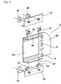
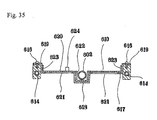
- the cover structure 611 is integrally mounted on the bottom chassis 613, 614.
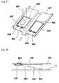
- the openings 621 of the stationary floor panel 617 for feet setting on the ground are covered from below with an opennable and closable floor panel section 630.
- the floor panel section 630 rotates around hinges 625 as indicated dashed lines in Fig. 37 until an end 631 of the floor panel section 630 opposite to the hinges 625 comes in contact with the ground G so as to brake and to stop the vehicle.
- the vehicle runs in the direction of the arrow, i.e., leftward as viewed in Fig. 38.
Landscapes
- Engineering & Computer Science (AREA)
- Mechanical Engineering (AREA)
- Automatic Cycles, And Cycles In General (AREA)
- Body Structure For Vehicles (AREA)
- Fittings On The Vehicle Exterior For Carrying Loads, And Devices For Holding Or Mounting Articles (AREA)
Applications Claiming Priority (11)
| Application Number | Priority Date | Filing Date | Title |
|---|---|---|---|
| JP2002012770A JP2004082744A (ja) | 2002-01-22 | 2002-01-22 | カバー体付自転車装置 |
| JP2002012770 | 2002-01-22 | ||
| JP2002058113A JP3728261B2 (ja) | 2002-03-05 | 2002-03-05 | カバー体付自転車装置 |
| JP2002058113 | 2002-03-05 | ||
| JP2002101090A JP2004082746A (ja) | 2002-04-03 | 2002-04-03 | 着脱カバー付自転車装置 |
| JP2002101090 | 2002-04-03 | ||
| JP2002120060 | 2002-04-23 | ||
| JP2002120060A JP2004082747A (ja) | 2002-04-23 | 2002-04-23 | 回転カバー付自転車装置 |
| JP2002145748A JP3851843B2 (ja) | 2002-05-21 | 2002-05-21 | 床付自転車装置 |
| JP2002145748 | 2002-05-21 | ||
| PCT/JP2002/007154 WO2003062037A1 (fr) | 2002-01-22 | 2002-07-15 | Bicyclette a enveloppe de protection |
Publications (2)
| Publication Number | Publication Date |
|---|---|
| EP1468903A1 true EP1468903A1 (fr) | 2004-10-20 |
| EP1468903A4 EP1468903A4 (fr) | 2008-03-19 |
Family
ID=27617869
Family Applications (1)
| Application Number | Title | Priority Date | Filing Date |
|---|---|---|---|
| EP02746045A Withdrawn EP1468903A4 (fr) | 2002-01-22 | 2002-07-15 | Bicyclette a enveloppe de protection |
Country Status (5)
| Country | Link |
|---|---|
| US (1) | US7090279B2 (fr) |
| EP (1) | EP1468903A4 (fr) |
| KR (1) | KR100516920B1 (fr) |
| CN (1) | CN1531494A (fr) |
| WO (1) | WO2003062037A1 (fr) |
Families Citing this family (14)
| Publication number | Priority date | Publication date | Assignee | Title |
|---|---|---|---|---|
| GB2386136A (en) * | 2002-03-08 | 2003-09-10 | Stanley Millward | A pivoting cover suitable for a vehicle |
| JP2005297642A (ja) * | 2004-04-07 | 2005-10-27 | Shirouma Science Co Ltd | 体力増進機能を持つ電動アシスト自転車 |
| CN100357150C (zh) * | 2004-07-12 | 2007-12-26 | 曹海洋 | 带有活动地板的封闭式二轮摩托车 |
| US7374190B2 (en) * | 2005-08-26 | 2008-05-20 | Jae Hyun Hong | Tricycle |
| KR101506366B1 (ko) * | 2008-09-08 | 2015-03-27 | 엘라드 오비드 | 부상방지 액세서리 |
| KR100975660B1 (ko) | 2008-10-16 | 2010-08-17 | 김희자 | 지붕달린 삼륜자전거 |
| WO2010044630A2 (fr) * | 2008-10-16 | 2010-04-22 | Kim Hija | Tricycle doté d'une bulle |
| US8287023B2 (en) * | 2008-11-13 | 2012-10-16 | Dick Bixler | Apparatus for the handicapped |
| NL2003332C2 (nl) * | 2009-08-05 | 2011-02-08 | Paul Gokkel | Opvouwbaar voertuig. |
| US8366171B2 (en) | 2010-09-18 | 2013-02-05 | Pond I Corp. | Vehicle enclosure apparatus |
| US10179504B2 (en) * | 2016-05-18 | 2019-01-15 | Polaris Industries Inc. | Sunshade for a vehicle |
| CN110077501B (zh) * | 2019-05-31 | 2024-02-13 | 重庆万虎成田摩托车制造有限公司 | 三轮车前篷 |
| CN113928451A (zh) * | 2021-11-25 | 2022-01-14 | 徐州汉邦车业有限公司 | 一种便于组装的三轮车驾驶室 |
| USD987547S1 (en) | 2021-12-06 | 2023-05-30 | Polaris Industries Inc. | Roof for vehicle |
Family Cites Families (32)
| Publication number | Priority date | Publication date | Assignee | Title |
|---|---|---|---|---|
| US1135337A (en) * | 1913-10-23 | 1915-04-13 | Etienne Bunau-Varilla | Wind-dividing apparatus for transport-vehicles with kinematic equilibrium. |
| DE906413C (de) * | 1951-07-10 | 1954-03-15 | Guenter Homann | Schutzverkleidung fuer Motorraeder und aehnlich betriebene einspurige Fahrzeuge |
| FR1139842A (fr) * | 1955-12-21 | 1957-07-05 | Carrosserie légère pour cycles, cyclomoteurs, motocycles et scooters | |
| JPS49119952A (fr) | 1973-03-22 | 1974-11-15 | ||
| JPS5041243A (fr) | 1973-08-20 | 1975-04-15 | ||
| USD245903S (en) * | 1976-05-14 | 1977-09-27 | Harris Jr James | Protective cover for a bicycle |
| JPS5426253A (en) | 1977-07-29 | 1979-02-27 | Ricoh Co Ltd | Welding method for tip end of plate-shaped body |
| US4313517A (en) * | 1978-11-24 | 1982-02-02 | American Microcar, Inc. | Lightweight electrically driven three-wheeled vehicle with low center of gravity and lightweight superstructure including improved braking system |
| JPS59199383A (ja) | 1983-04-26 | 1984-11-12 | 株式会社地域環境工学研究所 | 側車付き全天候型二輪車 |
| JPS6015069A (ja) | 1983-07-06 | 1985-01-25 | Kobe Steel Ltd | Al管の円周方向隅肉溶接方法 |
| JPS6077194A (ja) | 1983-10-03 | 1985-05-01 | Mitsubishi Electric Corp | 液相エピタキシヤル結晶成長装置 |
| JPS60145984U (ja) * | 1984-03-08 | 1985-09-27 | 高橋 伸介 | 車両から足だけ外に出す為のドア |
| JPS6090083A (ja) | 1984-06-04 | 1985-05-21 | セイレイ工業株式会社 | 内部観察容易な回転選別機 |
| JPS61155279A (ja) | 1984-12-27 | 1986-07-14 | 住友電気工業株式会社 | セラミツクスの製造方法 |
| JPH07114073B2 (ja) | 1985-04-26 | 1995-12-06 | 株式会社日立製作所 | 磁気バブルメモリ |
| US4973082A (en) * | 1987-09-09 | 1990-11-27 | Dan Kincheloe | Roll cage for personal motorized vehicles |
| JPH02145984A (ja) | 1988-11-26 | 1990-06-05 | Mitsubishi Electric Corp | レーダ |
| JPH0277194U (fr) * | 1988-12-01 | 1990-06-13 | ||
| JP2564047B2 (ja) | 1991-03-07 | 1996-12-18 | 岩名 滋 | 車両のキャビン形成装置 |
| CA2093153C (fr) * | 1993-04-01 | 2005-01-11 | Randy B. Gilbert | Abri souple pour conducteur de motocyclette |
| GB2284583B (en) * | 1993-12-10 | 1997-07-23 | Bothwell P W | Powered two-wheel vehicles |
| DE19636676C2 (de) * | 1995-11-11 | 1999-01-21 | Peter O C Yates | Kabine für ein Fahrrad |
| US5791718A (en) * | 1996-07-15 | 1998-08-11 | Boutin; Gerard | Cover assembly for a motorcycle |
| US5662372A (en) * | 1996-11-06 | 1997-09-02 | Lubkeman; Arnold F. | Flexible weather protective vehicle cover structure |
| IT236170Y1 (it) * | 1997-07-16 | 2000-07-26 | Nicola Pozio | Veicolo a due ruote dotato di abitacolo a protezione variabileaccessibile attraverso sportelli laterali |
| US6017076A (en) * | 1997-07-18 | 2000-01-25 | Belisle; William Redvers | Fairing and fairingless enclosures for two-, three-, and four-wheel automotive vehicles/riders/passengers/loads (FFE) |
| JPH1159553A (ja) | 1997-08-20 | 1999-03-02 | Katayama Chain Kk | チェーンテンショナー |
| JPH1159552A (ja) | 1997-08-25 | 1999-03-02 | Minoru Nakamura | 自転車 |
| FR2771069A1 (fr) * | 1997-11-20 | 1999-05-21 | Raymond Sgandura | Habitacle pour velo |
| JP2970650B2 (ja) | 1998-04-27 | 1999-11-02 | スズキ株式会社 | ルーフ付きスクータ型車両 |
| US6402220B2 (en) * | 2000-04-05 | 2002-06-11 | Edmund L. Allen | Portable enclosure |
| US20030218358A1 (en) * | 2002-05-24 | 2003-11-27 | Seonho Hahn | Dual mode vehicle side door |
-
2002
- 2002-07-15 EP EP02746045A patent/EP1468903A4/fr not_active Withdrawn
- 2002-07-15 KR KR10-2003-7006648A patent/KR100516920B1/ko not_active Expired - Fee Related
- 2002-07-15 WO PCT/JP2002/007154 patent/WO2003062037A1/fr not_active Ceased
- 2002-07-15 US US10/492,225 patent/US7090279B2/en not_active Expired - Fee Related
- 2002-07-15 CN CNA028034090A patent/CN1531494A/zh active Pending
Also Published As
| Publication number | Publication date |
|---|---|
| US20040251715A1 (en) | 2004-12-16 |
| US7090279B2 (en) | 2006-08-15 |
| EP1468903A4 (fr) | 2008-03-19 |
| CN1531494A (zh) | 2004-09-22 |
| KR20030083684A (ko) | 2003-10-30 |
| KR100516920B1 (ko) | 2005-09-23 |
| WO2003062037A1 (fr) | 2003-07-31 |
Similar Documents
| Publication | Publication Date | Title |
|---|---|---|
| EP1468903A1 (fr) | Bicyclette a enveloppe de protection | |
| US7281753B2 (en) | Vehicle enclosure | |
| US4632448A (en) | Light motor vehicles | |
| KR101262910B1 (ko) | 전동식 스텝장치 | |
| US6206446B1 (en) | ATV all-weather cab | |
| US7219948B2 (en) | Vehicle enclosure | |
| FI73177C (fi) | Svaengbar taklucka. | |
| US7422267B2 (en) | Vehicle enclosure | |
| JP2002532215A (ja) | ゴルフカートに関する改良 | |
| US3360295A (en) | Tractor cab assembly | |
| US6659526B2 (en) | Canopy and visor windshield for a mobility vehicle | |
| JP4124202B2 (ja) | 低速走行用小型車両のルーフ装置 | |
| US20060087149A1 (en) | Vehicle enclosure | |
| CN206528303U (zh) | 一种车门与一种车辆 | |
| US8430444B1 (en) | Vehicle covering system | |
| JPWO2003062037A1 (ja) | カバー体付自転車装置 | |
| JP2788428B2 (ja) | ゴルフカート | |
| JP3728261B2 (ja) | カバー体付自転車装置 | |
| JP2004082744A (ja) | カバー体付自転車装置 | |
| JP7520478B1 (ja) | 電動式ルーフ付きトライク | |
| JP2004262314A (ja) | 低速走行用小型車両のルーフ装置 | |
| JP3851843B2 (ja) | 床付自転車装置 | |
| TW200304886A (en) | Bicycle with cover | |
| US20200277015A1 (en) | External protection device for vehicles and heads | |
| JPH0585187A (ja) | 自動車の幌布張設構造 |
Legal Events
| Date | Code | Title | Description |
|---|---|---|---|
| PUAI | Public reference made under article 153(3) epc to a published international application that has entered the european phase |
Free format text: ORIGINAL CODE: 0009012 |
|
| 17P | Request for examination filed |
Effective date: 20040226 |
|
| AK | Designated contracting states |
Kind code of ref document: A1 Designated state(s): AT BE BG CH CY CZ DE DK EE ES FI FR GB GR IE IT LI LU MC NL PT SE SK TR |
|
| AX | Request for extension of the european patent |
Extension state: AL LT LV MK RO SI |
|
| A4 | Supplementary search report drawn up and despatched |
Effective date: 20080211 |
|
| RA4 | Supplementary search report drawn up and despatched (corrected) |
Effective date: 20080213 |
|
| STAA | Information on the status of an ep patent application or granted ep patent |
Free format text: STATUS: THE APPLICATION IS DEEMED TO BE WITHDRAWN |
|
| 18D | Application deemed to be withdrawn |
Effective date: 20080103 |