EP1468907B1 - Dispositif et procédés pour attacher des panneaux à des structures de support - Google Patents
Dispositif et procédés pour attacher des panneaux à des structures de support Download PDFInfo
- Publication number
- EP1468907B1 EP1468907B1 EP04076152A EP04076152A EP1468907B1 EP 1468907 B1 EP1468907 B1 EP 1468907B1 EP 04076152 A EP04076152 A EP 04076152A EP 04076152 A EP04076152 A EP 04076152A EP 1468907 B1 EP1468907 B1 EP 1468907B1
- Authority
- EP
- European Patent Office
- Prior art keywords
- elongated
- coupled
- elongated channel
- panel
- channel
- Prior art date
- Legal status (The legal status is an assumption and is not a legal conclusion. Google has not performed a legal analysis and makes no representation as to the accuracy of the status listed.)
- Expired - Lifetime
Links
- 238000000034 method Methods 0.000 title claims abstract description 13
- 230000008878 coupling Effects 0.000 claims abstract description 15
- 238000010168 coupling process Methods 0.000 claims abstract description 15
- 238000005859 coupling reaction Methods 0.000 claims abstract description 15
- 238000009413 insulation Methods 0.000 claims description 8
- 230000000712 assembly Effects 0.000 description 13
- 238000000429 assembly Methods 0.000 description 13
- 238000002955 isolation Methods 0.000 description 7
- 239000000463 material Substances 0.000 description 7
- 238000009434 installation Methods 0.000 description 5
- 238000007667 floating Methods 0.000 description 4
- 239000000853 adhesive Substances 0.000 description 2
- 230000001070 adhesive effect Effects 0.000 description 2
- 238000010276 construction Methods 0.000 description 2
- 239000013536 elastomeric material Substances 0.000 description 2
- 239000011521 glass Substances 0.000 description 2
- 229920002725 thermoplastic elastomer Polymers 0.000 description 2
- 229910000831 Steel Inorganic materials 0.000 description 1
- XAGFODPZIPBFFR-UHFFFAOYSA-N aluminium Chemical compound [Al] XAGFODPZIPBFFR-UHFFFAOYSA-N 0.000 description 1
- 229910052782 aluminium Inorganic materials 0.000 description 1
- 230000005540 biological transmission Effects 0.000 description 1
- 239000002131 composite material Substances 0.000 description 1
- 238000013016 damping Methods 0.000 description 1
- 230000003247 decreasing effect Effects 0.000 description 1
- 238000011900 installation process Methods 0.000 description 1
- 239000011810 insulating material Substances 0.000 description 1
- 239000000203 mixture Substances 0.000 description 1
- 229920001296 polysiloxane Polymers 0.000 description 1
- -1 siloxane compound Chemical class 0.000 description 1
- 239000010959 steel Substances 0.000 description 1
- 229920001169 thermoplastic Polymers 0.000 description 1
- 239000004416 thermosoftening plastic Substances 0.000 description 1
Images



Classifications
-
- B—PERFORMING OPERATIONS; TRANSPORTING
- B64—AIRCRAFT; AVIATION; COSMONAUTICS
- B64C—AEROPLANES; HELICOPTERS
- B64C1/00—Fuselages; Constructional features common to fuselages, wings, stabilising surfaces or the like
- B64C1/06—Frames; Stringers; Longerons ; Fuselage sections
- B64C1/066—Interior liners
-
- F—MECHANICAL ENGINEERING; LIGHTING; HEATING; WEAPONS; BLASTING
- F16—ENGINEERING ELEMENTS AND UNITS; GENERAL MEASURES FOR PRODUCING AND MAINTAINING EFFECTIVE FUNCTIONING OF MACHINES OR INSTALLATIONS; THERMAL INSULATION IN GENERAL
- F16B—DEVICES FOR FASTENING OR SECURING CONSTRUCTIONAL ELEMENTS OR MACHINE PARTS TOGETHER, e.g. NAILS, BOLTS, CIRCLIPS, CLAMPS, CLIPS OR WEDGES; JOINTS OR JOINTING
- F16B5/00—Joining sheets or plates, e.g. panels, to one another or to strips or bars parallel to them
- F16B5/06—Joining sheets or plates, e.g. panels, to one another or to strips or bars parallel to them by means of clamps or clips
- F16B5/0685—Joining sheets or plates to strips or bars
-
- F—MECHANICAL ENGINEERING; LIGHTING; HEATING; WEAPONS; BLASTING
- F16—ENGINEERING ELEMENTS AND UNITS; GENERAL MEASURES FOR PRODUCING AND MAINTAINING EFFECTIVE FUNCTIONING OF MACHINES OR INSTALLATIONS; THERMAL INSULATION IN GENERAL
- F16B—DEVICES FOR FASTENING OR SECURING CONSTRUCTIONAL ELEMENTS OR MACHINE PARTS TOGETHER, e.g. NAILS, BOLTS, CIRCLIPS, CLAMPS, CLIPS OR WEDGES; JOINTS OR JOINTING
- F16B5/00—Joining sheets or plates, e.g. panels, to one another or to strips or bars parallel to them
- F16B5/12—Fastening strips or bars to sheets or plates, e.g. rubber strips, decorative strips for motor vehicles, by means of clips
Definitions
- Interior wall panels are attached to a frame or other support structure of the vehicle.
- the passenger compartments of most modem aircraft, trains, and buses are equipped with interior wall panels.
- Interior wall panels may improve the passenger's enjoyment by reducing noise or improving the aesthetic quality of the passenger's environment.
- FIGURE 1 is an isometric view of an aircraft interior 10 prior to installation of wall panels 12 (not shown) in accordance with the prior art.
- the aircraft interior 10 includes a plurality of elongated frame members 14, and a plurality of isolation mounts 16 are attached to each frame member 14.
- An enlarged isometric view of one of the isolation mounts 16 is shown in FIGURE 2 .
- the isolation mount 16 includes a mounting plate 18 having a pair of elongated slots 20 disposed therethrough.
- a floating nut 21 is clipped to the mounting plate 18 near each of the elongated slots 20.
- Mounting arms 22 (only one visible) extend from the mounting plate 18 along the sides of the frame member 14 and are secured to the frame member 14 by a fastener 24 ( e .
- a wall panel 12 is positioned beside the mounting plate 18, with a pair of hole 24 in the wall panel 12 aligned with the floating nuts 21.
- a mounting screw 26 is then passed through each hole 24 and secured to the corresponding floating nut 21, securing the wall panel 12 to the frame member 14.
- each wall panel 12 typically uses about eighty parts to secure into position, including ten isolation mounts 16 with two fasteners 24 per isolation mount 16, two floating nuts 21 per isolation mount 16, eight mounting screws 26, and various other components.
- the process of installing the wall panels 12 using the prior art installation may involve multiple tools and more than one person to accomplish. Consequently, there is an unmet need to reduce the number of parts, tools, and personnel, and associated expenses to install wall panels within the aircraft interior.
- US 2002/0195595 which is regarded as the closest prior art and discloses all the features of the preamble of the independent claim 1, describes a structural glass panel railing system for mounting a glass panel to a floor.
- the system includes a shoe that is secured to a floor that is used for mounting a base member and a pair of elongated sockets extend along the length of the shoe.
- the base member includes a lower body portion with a downwardly extending full locking projection at one side and a partial locking projection at the other, where the projections are inserted into the elongated sockets of the shoe for securing the base member to the shoe.
- the present invention is directed to apparatus and methods for attaching wall panels to support structures.
- Apparatus and methods in accordance with the present invention may advantageously provide a simplified, more efficient method for attaching panels to support structures, thereby improving the efficiency and reducing the expense involved in the installation process.
- the inventive apparatus and methods may also inhibit the transmission of structure-borne vibration from the support structure to the wall panels.
- the present invention relates to apparatus and methods for attaching wall panels to support structures. Many specific details of certain embodiments of the invention are set forth in the following description and in FIGURES 3-9 to provide a thorough understanding of such embodiments. One skilled in the art, however, will understand that the present invention may have additional embodiments, or that the present invention may be practiced without several of the details described in the following description.
- FIGURE 3 is an end elevational view of a panel mounting assembly 100 in an exploded (or disassembled) position in accordance with an embodiment of the invention.
- the panel mounting assembly 100 includes a plurality of attachment assemblies 110.
- Each attachment assembly 110 includes a support member 112 that is coupled to an adjoining frame member 14, and a mounting member 114 that is coupled to an edge portion 116 of a panel 118.
- the frame member 14 may be part of an aircraft airframe
- the panel 118 may be an interior wall panel of a passenger compartment of the aircraft.
- a mounting layer 113 may be disposed between the support member 112 and the frame member 14.
- the mounting layer 113 may be formed of any desirable material, such as an elastomeric material or other material suitable for damping or eliminating vibrations that may otherwise be transmitted from the frame member 14 to the support member 112.
- the mounting layer 113 may be formed of an elastomeric material characterized by one or more of the following parameters: an elongation between 350% to 500%, a hardness durometer (D) between approximately 50 to 60, and a modulus of approximately 90,000 to 150,000 psi.
- the mounting layer 113 may be formed of a commercially-available material known as HYTREL®, a thermoplastic elastomer (TPE), a siloxane compound, a modified silicone, or any other suitable material or combination of materials.
- HYTREL® a commercially-available material known as HYTREL®, a thermoplastic elastomer (TPE), a siloxane compound, a modified silicone, or any other suitable material or combination of materials.
- FIGURE 4 is an enlarged elevational view of one of the attachment assemblies 110 of the panel mounting assembly 100 of FIGURE 3 .
- the support member 112 has an elongated channel 120 disposed therein.
- the channel 120 is bounded on either side by a sidewall member 122.
- a retaining member 124 projects inwardly from an inner surface of each sidewall member 122 into the channel 120.
- a mounting member 126 projects outwardly from an outer surface of each sidewall member 122.
- a first securing member (or fastener) 128 is disposed on each mounting member 126.
- the mounting member 114 includes a base portion 130 and a head portion 132.
- the base portion 130 projects outwardly from the head portion 132 and is adapted to engage with the elongated channel 120, as described more fully below.
- the head portion 132 has a pair of slots 134 disposed therein. The slots 134 are disposed on opposing sides of the head portion 132 and are adapted to fittingly receive the edge portion 116 of the panel 118.
- the panel mounting assembly 100 may further include an insulation assembly 140 having a shell member 142 adapted to form a recess 144.
- An insulating material 146 may be formed in the recess 144.
- Each end 148 of the shell member 142 may include a second securing member 150 that is adapted to be coupled to the first securing member 128 of the support member 112.
- each attachment assembly 110 may be used to attach both the panel 118 and the insulation assembly 140 to the frame member 14.
- first and second securing members 128, 150 may be any type of suitable coupling members.
- the first and second securing members 128, 150 may be so-called tongue-in-groove or ZIP-LOC® type securing members as shown in FIGURES 3 and 4 .
- the first and second securing members 128, 150 may be snaps, hook-and-loop fastener strips (e.g. VELCRO® strips), adhesive, rivets, screws, or any other suitable securing or fastening devices.
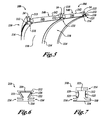
- FIGURE 5 is an isometric, partial sectional view of the panel mounting assembly 100 of FIGURE 3 in an assembled position.
- two panels 118 and two insulation assemblies 140 are mounted onto three frame members 14 using three attachment assemblies 110.
- the panel mounting assembly 100 may be assembled by attaching the support member 112 of each attachment assembly 110 to one of the frame members 14.
- the attachment of the support member 112 to the frame member 14 may be accomplished in any desired manner, including, for example, by rivets, screws, adhesive, thermal bonding, or using any other suitable attachment mechanism.
- the mounting layer 113 may be positioned between the frame member 14 and the support member 112 to reduce vibration, or alternately, the mounting layer may be omitted.
- the support member 112 may be integrally formed with the frame member 14.
- the insulation assemblies 140 may then be installed by coupling the second coupling members 150 on the insulation assemblies 140 ( Figure 4 ) with the first coupling members 128 on the support member 112.
- the insulation assemblies 140 may be coupled to the support members 112 prior to their attachment to the frame members 14, or alternately, the insulation assemblies 140 may be omitted.
- the mounting members 114 may then be coupled to the panels 118 by inserting the edge portions 116 of the panels 118 into the slots 134.
- the mounting members 114 may then be coupled to the support members 112 by engaging the base portion 130 of each mounting member 114 into the channel 120 of the corresponding support member 112.
- the panels 118 may be coupled to the mounting member 114 after the mounting member 114 is coupled to the support member 112, or a combination of these alternate possibilities may be employed.
- the base portion 130 may be engaged into the channel 120 in a variety of suitable ways.
- the base portion 130 may be engaged into the channel *120 by slideably engaging the base portion 130 into an open end 121 of the channel 120 ( FIGURE 5 ).
- the base portion 130 may then be slid along a longitudinal axis 123 of the channel 120 until the mounting member 114 is properly positioned with respect to the support member 112 (e.g. aligned with the support member 112).
- the mounting member 114 may be positioned near the support member 112, and the base portion 130 may simply be snapped or force-fit into the channel 120 of the support member 112.
- the base portion 130 may be adapted to engage with the cross-sectional shape of the channel 120 such that, under normal operating conditions, the base portion 130 is substantially constrained within the elongated channel 120 from movement relative to the support member 112 in directions other than along the longitudinal axis 123 of the channel 120.
- the base portion 130 is engaged into the channel 120 but is constrained from movement out of the channel 120 by the relatively narrow portion of the cross-sectional shape of the channel 120 created by the inwardly-projecting retaining members 124.
- the ends of the channel 120 may then be blocked, or the base portion 130 otherwise secured within the channel 120, to prevent undesired movement of the base portion 130 along the longitudinal axis 123 of the channel 120.
- the panel mounting assembly 100 advantageously provides a simplified, more efficient method for attaching panels 118 to adjoining support structures 14.
- the number of parts involved in the installation is substantially decreased, along with the number of tools required for the operation, in comparison with the prior art. Overall, the efficiency of the process of installing panels within vehicles, including within the passenger compartments of aircraft, may be improved, and the amount of labor and expense involved in the operation reduced.
- the panel mounting assembly 100 may also reduce or eliminate structure-borne vibration that would otherwise be transmitted from the support structures 14 to the panels 118, which may further enhance passenger comfort within, for example, the interior of a passenger aircraft.
- FIGURES 6 and 7 show enlarged, end elevational views of attachment assemblies in accordance with alternate embodiments of the invention.
- the attachment assembly 210 includes a support member 212 having sloping sidewalls 222 that form a channel 220 having a partial (or truncated) triangular cross-sectional shape.
- the mounting member 214 includes a correspondingly-shaped base portion 230.
- the attachment assembly 310 may include a support member 312 that includes a channel 320 having a cross-sectional shape with a narrow portion 321 that is located at a position between a bottom wall 323 of the channel 320 and an outer opening 325 of the channel 320.
- the mounting member 314 may then include a base portion 330 having a corresponding cross-sectional shape.
- a wide variety of suitable cross-sectional shapes of channels and base portions may be used in accordance with the teachings of the present invention.
- the mounting assembly may be further modified such that the channel is disposed in the mounting member and the base portion that engages into the channel is part of the support member.
- the first member 314 may be coupled to an adjoining frame member 14 ( FIGURES 3-5 ), and the second member 312 may include one or more slots 334 (shown in phantom lines) that engage with an edge portion of a panel 118.
- the second member 312 may be engaged onto the first member 314 in the manner described above to attach a panel 118 to the frame member 14.
- FIGURE 8 is an isometric, partial sectional view of a panel mounting assembly 400 in accordance with another embodiment of the invention.
- a pair of attachment assemblies 410 are mounted transversely to a plurality of frame members 14, and a panel 118 is mounted therebetween.
- the above-noted advantages of the invention may be realized in a panel mounting assembly 400 having attachment assemblies 410 that are transverse (e.g. perpendicular or otherwise) to the adjoining supporting members.
- attachment to elongated frame members 14 the invention is not limited to operation with such members, and in fact can be used to attach panels to virtually any type of support structure, including, for example, flat walls or non-vertical frame members.
- the attachment and mounting assemblies of the present invention may be employed with support structures of virtually any design, construction, or material composition, including, for example, support structures made of aluminum, steel, thermoplastics, composites, or any other desired materials.
- FIGURE 9 is a side elevational view of an aircraft 500 having wall panels 118 installed using a panel mounting assembly 502 (not visible) in accordance with the invention.
- All of the components of the aircraft 500, other than the panel mounting assembly 502 of the present invention, are of generally known construction and, for the sake of brevity, will not be described in detail herein.
- the aircraft 500 includes one or more propulsion units 504, wings 506 (or other lifting surfaces), a tail assembly 508, a landing assembly 510, a control system 512 (not visible), and a host of other systems and subsystems that enable proper operation of the aircraft 500.
- the aircraft 500 shown in FIGURE 9 is generally representative of a commercial passenger aircraft, including, for example, the 737, 747, 757, 767, and 777 models commercially-available from The Boeing Company.
- the apparatus and methods disclosed herein, however, may also be employed in any other types of aircraft, such as rotary aircraft or manned military aircraft, including those described, for example, in The Illustrated Encyclopedia of Military Aircraft by Enzo Angelucci, published by Book Sales Publishers, September 2001.
Landscapes
- Engineering & Computer Science (AREA)
- Mechanical Engineering (AREA)
- Aviation & Aerospace Engineering (AREA)
- Connection Of Plates (AREA)
- Joining Of Building Structures In Genera (AREA)
- Finishing Walls (AREA)
Claims (14)
- Appareil destiné à fixer un panneau (118) à une structure attenante, l'appareil comprenant:un premier organe (112) ayant un premier canal allongé (120), le premier organe (112) étant adapté pour être couplé à la structure attenante; etun second organe (114) ayant une portion de tête (132) et une portion de base (130), la portion de tête (132) ayant au moins une fente (134) disposée à l'intérieur de celle-ci, la fente (134) étant adaptée pour recevoir une portion de bord du panneau (118), la portion de base (132) ayant un second organe de couplage allongé adapté pour être couplé au premier organe de couplage allongé, caractérisé en ce que le premier organe (112) comprend des première et seconde parois latérales (122), le canal allongé (120) étant disposé entre les surfaces internes des parois latérales, au moins une des première et seconde parois latérales ayant une surface externe comprenant un bras de montage (126) en saillie vers l'extérieur à partir de la paroi latérale (122), le bras de montage (126) comprenant un organe de fixation (128).
- Appareil selon la revendication 1, dans lequel le premier canal allongé (120) présente au moins une extrémité ouverte et dans lequel le second organe de couplage allongé comprend une saillie allongée qui peut être mise en prise dans l'extrémité ouverte et coulissée le long d'un axe longitudinal du canal allongé (120), la saillie allongée étant sensiblement contrainte dans le canal allongé (120) du point de vue d'un mouvement par rapport au premier organe (112) dans des directions autres que le long de l'axe longitudinal.
- Appareil selon la revendication 2, dans lequel le canal allongé (120) présente une surface de base s'étendant entre les surfaces latérales et une ouverture externe opposée à la surface de base, les surfaces latérales et la surface de base définissant une forme en coupe transversale ayant une portion rétrécie qui est espacée de la surface de base.
- Appareil selon la revendication 1, 2 ou 3, dans lequel au moins l'une des surfaces latérales comprend un organe de rétention (124) en saillie vers l'intérieur dans le canal allongé (120).
- Appareil selon l'une quelconque des revendications 1 à 4, dans lequel le premier organe (112) est adapté pour être couplé à la structure attenante de telle sorte que l'axe longitudinal du canal allongé (120) est orienté au moins partiellement le long de la structure attenante.
- Appareil selon l'une quelconque des revendications 1 à 5, dans lequel le premier organe (112) est adapté pour être couplé à la structure attenante de telle sorte que l'axe longitudinal du canal allongé est orienté transversalement à la structure attenante.
- Appareil selon l'une quelconque des revendications 1 à 6, dans lequel le second organe de couplage allongé comprend un canal allongé présentant au moins une extrémité ouverte, et dans lequel le premier organe de couplage allongé comprend une saillie allongée qui peut être mise en prise dans l'extrémité ouverte et coulissée le long d'un axe longitudinal du canal allongé, la saillie allongée étant sensiblement contrainte dans le canal allongé du point de vue d'un mouvement par rapport au second organe dans des directions autres que le long de l'axe longitudinal.
- Appareil selon l'une quelconque des revendications 1 à 7, dans lequel la portion de tête (132) présente des première et seconde fentes (134) disposées sur des côtés opposés de celle-ci.
- Appareil selon l'une quelconque des revendications 1 à 8, dans lequel la portion de tête (132) comprend une portion sensiblement en T comportant des première et seconde portions en extension vers l'extérieur, chaque portion en extension vers l'extérieur comportant une fente (134) disposée à l'intérieur de celle-ci.
- Appareil selon la revendication 1, dans lequel l'organe de fixation comprend un organe de fixation à languette et rainure.
- Appareil selon les revendications 1 à 10, comprenant en outre un ensemble d'isolation (140) couplé à l'organe de fixation.
- Aéronef comprenant un appareil selon l'une quelconque des revendications 1 à 11.
- Aéronef selon la revendication 12, comprenant:une structure de support; etun ensemble de paroi couplé fonctionnellement à la structure de support, l'ensemble de paroi comprenant:un panneau ayant une première portion de bord;un premier organe ayant un premier organe de couplage allongé, le premier organe étant couplé à la structure de support; etun second organe ayant une portion de tête et une portion de base, la portion de tête ayant au moins une fente disposée à l'intérieur de celle-ci, la première portion de bord du panneau étant disposée dans la fente, la portion de base ayant un second organe de couplage allongé adapté pour être couplé au premier organe de couplage allongé.
- Procédé de fixation d'un panneau à une structure utilisant l'appareil de la revendication 1.
Applications Claiming Priority (2)
| Application Number | Priority Date | Filing Date | Title |
|---|---|---|---|
| US10/418,400 US6871822B2 (en) | 2003-04-18 | 2003-04-18 | Apparatus and methods of attaching panels to support structures |
| US418400 | 2003-04-18 |
Publications (5)
| Publication Number | Publication Date |
|---|---|
| EP1468907A2 EP1468907A2 (fr) | 2004-10-20 |
| EP1468907A3 EP1468907A3 (fr) | 2006-12-13 |
| EP1468907B1 true EP1468907B1 (fr) | 2008-07-23 |
| EP1468907B8 EP1468907B8 (fr) | 2008-10-15 |
| EP1468907B2 EP1468907B2 (fr) | 2011-07-20 |
Family
ID=32908355
Family Applications (1)
| Application Number | Title | Priority Date | Filing Date |
|---|---|---|---|
| EP04076152A Expired - Lifetime EP1468907B2 (fr) | 2003-04-18 | 2004-04-15 | Dispositif et procédés pour attacher des panneaux à des structures de support |
Country Status (5)
| Country | Link |
|---|---|
| US (3) | US6871822B2 (fr) |
| EP (1) | EP1468907B2 (fr) |
| JP (1) | JP4726430B2 (fr) |
| AT (1) | ATE402069T1 (fr) |
| DE (1) | DE602004015186D1 (fr) |
Cited By (2)
| Publication number | Priority date | Publication date | Assignee | Title |
|---|---|---|---|---|
| US8979027B2 (en) | 2012-05-31 | 2015-03-17 | The Boeing Company | Wall installation system and method |
| US9096303B2 (en) | 2013-01-14 | 2015-08-04 | The Boeing Company | Airplane sidewall attachment device |
Families Citing this family (22)
| Publication number | Priority date | Publication date | Assignee | Title |
|---|---|---|---|---|
| US7527223B2 (en) * | 2006-04-06 | 2009-05-05 | The Boeing Company | Interior panel attachment system |
| DE102006017241B4 (de) | 2006-04-12 | 2017-11-23 | Airbus Operations Gmbh | Ebene Spaltabdeckung für Kabinenverkleidungen |
| DE102006026170B4 (de) * | 2006-06-06 | 2012-06-21 | Airbus Operations Gmbh | Flugzeugrumpfstruktur und Verfahren zu deren Herstellung |
| DE102006026169B4 (de) * | 2006-06-06 | 2012-06-21 | Airbus Operations Gmbh | Flugzeugrumpfstruktur und Verfahren zu deren Herstellung |
| DE102006026168A1 (de) | 2006-06-06 | 2008-01-31 | Airbus Deutschland Gmbh | Flugzeugrumpfstruktur und Verfahren zu deren Herstellung |
| DE102006039290A1 (de) | 2006-08-22 | 2008-03-13 | Airbus Deutschland Gmbh | Rahmenelement, Flugzeugkomponentenmontagesystem sowie Verfahren zur Montage einer Komponente in einem Flugzeug |
| WO2008022773A1 (fr) * | 2006-08-22 | 2008-02-28 | Airbus Deutschland Gmbh | Élément de châssis, système d'assemblage de composants d'aéronef et procédé de montage d'un composant dans un aéronef |
| DE102007011627A1 (de) * | 2007-01-23 | 2008-07-31 | Airbus Deutschland Gmbh | Innenverkleidung für ein Luftfahrzeug |
| GB0704879D0 (en) * | 2007-03-14 | 2007-04-18 | Rolls Royce Plc | A Casing arrangement |
| US20090033040A1 (en) * | 2007-07-31 | 2009-02-05 | Vought Aircraft Industries, Inc. | Automated fiber placement mandrel joint configuration |
| ES2355998B1 (es) * | 2008-04-30 | 2012-02-27 | Forplan Metales, S.A | Sistema de unión entre revestimientos y elementos estructurales que los soportan. |
| CA2731974A1 (fr) * | 2008-07-30 | 2010-02-04 | Aircelle | Panneau d'attenuation acoustique pour nacelle de moteur d'aeronef |
| WO2010144010A1 (fr) | 2009-06-11 | 2010-12-16 | Saab Ab | Joint composite longitudinal structural pour structure d'avion |
| US20120074265A1 (en) * | 2009-06-11 | 2012-03-29 | Saab Ab | Nano-reinforced radius filler for an aircraft structure and a method of producing an aircraft structure comprising such filler |
| US8317135B2 (en) * | 2010-04-19 | 2012-11-27 | Sabreliner Corporation | Flexible mounting assembly for an air frame structure |
| DE102011085396A1 (de) * | 2011-10-28 | 2013-05-02 | Airbus Operations Gmbh | Befestigungsanordnung für plattenförmige Verkleidungsbauteile, Verkleidungsanordnung sowie Luft- oder Raumfahrzeug |
| US9109353B1 (en) * | 2013-08-13 | 2015-08-18 | The Boeing Company | Mounting assembly and method for connecting sidewall panels to a support structure |
| CN104627353A (zh) * | 2013-11-08 | 2015-05-20 | 空中客车运营简化股份公司 | 用于飞机的构件的连接装置 |
| CN106660627B (zh) | 2014-04-25 | 2020-06-16 | 庞巴迪公司 | 内部飞机特征的缓冲区 |
| US9682763B2 (en) | 2015-05-12 | 2017-06-20 | The Boeing Company | Apparatus and methods for attaching panels to support structures |
| US10501963B1 (en) * | 2018-12-17 | 2019-12-10 | Nanning Fugui Precision Industrial Co., Ltd. | Locking device |
| EP4524031A1 (fr) * | 2023-09-12 | 2025-03-19 | Airbus Operations GmbH | Agencement de revêtement intérieur d'aéronef, couvercle d'espace longitudinal, panneau intérieur et procédé d'installation |
Family Cites Families (24)
| Publication number | Priority date | Publication date | Assignee | Title |
|---|---|---|---|---|
| US2219714A (en) | 1938-01-12 | 1940-10-29 | Carey Philip Mfg Co | Panel assembly unit |
| US2877970A (en) * | 1955-12-21 | 1959-03-17 | Douglas Aircraft Co Inc | Vibration damping connection |
| US2925050A (en) † | 1957-01-09 | 1960-02-16 | Pullman Inc | Side frame construction and finish |
| DE2149831A1 (de) * | 1971-10-06 | 1973-04-12 | Holzaepfel Kg Moebel Christian | Beschlag zum aufhaengen eines bauteils an einem tragpfosten |
| US3882652A (en) * | 1973-08-02 | 1975-05-13 | United States Gypsum Co | Demountable partition assembly and studs therefor |
| US3875717A (en) * | 1973-08-30 | 1975-04-08 | Wolfgang Moeller | Unitary device for joining removable ceiling tile to hanger member |
| US3976269A (en) * | 1974-12-19 | 1976-08-24 | The Boeing Company | Intrinsically tuned structural panel |
| AU67675S (en) | 1975-08-29 | 1975-12-04 | Commonwealth Aluminium Corporation Ltd | fixing clip for roofing sheets |
| NL8101131A (nl) | 1981-03-09 | 1982-10-01 | Veldhoen Isolatie Bv | Inrichting voor het bevestigen van gevelpanelen aan een achterliggende draagconstructie. |
| US4587774A (en) * | 1983-11-14 | 1986-05-13 | United States Gypsum Company | System adapted to support a cantilevered load at a partition break |
| DE3528316A1 (de) † | 1985-06-26 | 1987-01-02 | Hunter Douglas Metalldecken Pr | Tragschienenprofil fuer verkleidungen |
| US4671470A (en) * | 1985-07-15 | 1987-06-09 | Beech Aircraft Corporation | Method for fastening aircraft frame elements to sandwich skin panels covering same using woven fiber connectors |
| US4799631A (en) † | 1987-02-18 | 1989-01-24 | Atr International, Inc. | Aircraft shell module |
| US5560102A (en) * | 1992-10-13 | 1996-10-01 | The Boeing Company | Panel and fuselage assembly |
| US5647181A (en) * | 1994-10-11 | 1997-07-15 | Hunts; Larry David | Construction system and method for connecting rigid sheet-like panels together into doll houses, play houses, utility sheds and other structures |
| GB2297336B (en) * | 1995-01-28 | 1997-04-16 | Brian Harry Kelly | Junction members and their uses |
| FR2738025B1 (fr) † | 1995-08-23 | 1997-11-07 | Filippo Agostini | Dispositif d'agrafage de pierres et carrelages pour revetement de facade d'immeuble d'habitation et industriel |
| US5876023A (en) * | 1996-09-18 | 1999-03-02 | Lord Corporation | Vibration isolation insert for aircraft floor planels and the like |
| US6444291B2 (en) | 1997-08-27 | 2002-09-03 | Tamko Roofing Products, Inc. | Rollable asphaltic protection course |
| US6517056B2 (en) * | 2000-03-30 | 2003-02-11 | John D. Shepherd | Railing assembly |
| ATE292222T1 (de) † | 2000-07-14 | 2005-04-15 | Eurogramco Sl | Vorrichtung zur verkleidung |
| US6786453B2 (en) * | 2001-10-25 | 2004-09-07 | The Boeing Company | Snap-in window assembly and method |
| ATE443188T1 (de) † | 2002-02-14 | 2009-10-15 | Eurogramco Sl | Verkleidungssystem für fassaden von bauwerken |
| US6712316B2 (en) * | 2002-08-01 | 2004-03-30 | The Boeing Company | Snap-on sidewall assembly |
-
2003
- 2003-04-18 US US10/418,400 patent/US6871822B2/en not_active Expired - Lifetime
-
2004
- 2004-04-15 AT AT04076152T patent/ATE402069T1/de not_active IP Right Cessation
- 2004-04-15 EP EP04076152A patent/EP1468907B2/fr not_active Expired - Lifetime
- 2004-04-15 DE DE602004015186T patent/DE602004015186D1/de not_active Expired - Lifetime
- 2004-04-16 JP JP2004122004A patent/JP4726430B2/ja not_active Expired - Lifetime
-
2005
- 2005-02-25 US US11/067,076 patent/US7416157B2/en not_active Expired - Lifetime
-
2008
- 2008-06-25 US US12/145,748 patent/US7578478B2/en not_active Expired - Lifetime
Cited By (2)
| Publication number | Priority date | Publication date | Assignee | Title |
|---|---|---|---|---|
| US8979027B2 (en) | 2012-05-31 | 2015-03-17 | The Boeing Company | Wall installation system and method |
| US9096303B2 (en) | 2013-01-14 | 2015-08-04 | The Boeing Company | Airplane sidewall attachment device |
Also Published As
| Publication number | Publication date |
|---|---|
| EP1468907A3 (fr) | 2006-12-13 |
| EP1468907B2 (fr) | 2011-07-20 |
| JP4726430B2 (ja) | 2011-07-20 |
| EP1468907B8 (fr) | 2008-10-15 |
| US20080258007A1 (en) | 2008-10-23 |
| US7416157B2 (en) | 2008-08-26 |
| US6871822B2 (en) | 2005-03-29 |
| ATE402069T1 (de) | 2008-08-15 |
| EP1468907A2 (fr) | 2004-10-20 |
| US7578478B2 (en) | 2009-08-25 |
| JP2004314959A (ja) | 2004-11-11 |
| DE602004015186D1 (de) | 2008-09-04 |
| US20040206853A1 (en) | 2004-10-21 |
| US20080156934A1 (en) | 2008-07-03 |
Similar Documents
| Publication | Publication Date | Title |
|---|---|---|
| US7578478B2 (en) | Attaching panels to support structures in an aircraft | |
| CN106364677B (zh) | 飞行器立体空间集成型附接装置 | |
| US7059565B2 (en) | Aircraft frame hole patterns and brackets, and associated methods | |
| KR101496778B1 (ko) | 케이블 레귤레이터 레일 및 스냅인 풀리를 구비한 캐리어 | |
| EP1977936B1 (fr) | Structure d'assemblage d'élément d'absorption et son procédé d'assemblage | |
| CA2564348C (fr) | Support de marchepied monobloc | |
| CN101311011B (zh) | 用于公共汽车的车顶空调 | |
| CA1220920A (fr) | Dispositif de fixation de cloisons sur des elements de charpente | |
| US20110067206A1 (en) | Trim Panel Attachment Assembly With Anti-Rotation Flange | |
| US11642984B2 (en) | Seat attachment system for a mass transit vehicle | |
| JP3709963B2 (ja) | 鉄道車両用車体構造 | |
| CN103930328B (zh) | 连接件、连接装置和轨道车辆 | |
| US10974774B2 (en) | Air guide device for a vehicle | |
| JP4476799B2 (ja) | 鉄道車両の内装構造 | |
| CN213574849U (zh) | 一种风机底盘及风机段 | |
| JP7759845B2 (ja) | 鉄道車両 | |
| US7562846B2 (en) | Window retaining system | |
| KR101956473B1 (ko) | 철도차량의 바닥 구조 | |
| EP4678532A1 (fr) | Système et procédé de fixation d'un ensemble siège à des rails de siège à l'intérieur d'une cabine interne d'un véhicule | |
| CN211468114U (zh) | 公交车风道用一体式铝型材 | |
| JPH0232888Y2 (fr) | ||
| KR200209630Y1 (ko) | 철도차량의 냉난방용 덕트 | |
| JP2505015Y2 (ja) | トラックキャブの前端部車体構造 | |
| JP2001180482A (ja) | 鉄道車輛の側天井ユニット | |
| KR20010001667U (ko) | 철도차량의 객실실내등 설치 구조체 |
Legal Events
| Date | Code | Title | Description |
|---|---|---|---|
| PUAI | Public reference made under article 153(3) epc to a published international application that has entered the european phase |
Free format text: ORIGINAL CODE: 0009012 |
|
| AK | Designated contracting states |
Kind code of ref document: A2 Designated state(s): AT BE BG CH CY CZ DE DK EE ES FI FR GB GR HU IE IT LI LU MC NL PL PT RO SE SI SK TR |
|
| AX | Request for extension of the european patent |
Extension state: AL HR LT LV MK |
|
| PUAL | Search report despatched |
Free format text: ORIGINAL CODE: 0009013 |
|
| AK | Designated contracting states |
Kind code of ref document: A3 Designated state(s): AT BE BG CH CY CZ DE DK EE ES FI FR GB GR HU IE IT LI LU MC NL PL PT RO SE SI SK TR |
|
| AX | Request for extension of the european patent |
Extension state: AL HR LT LV MK |
|
| 17P | Request for examination filed |
Effective date: 20070427 |
|
| AKX | Designation fees paid |
Designated state(s): AT BE BG CH CY CZ DE DK EE ES FI FR GB GR HU IE IT LI LU MC NL PL PT RO SE SI SK TR |
|
| 17Q | First examination report despatched |
Effective date: 20071116 |
|
| GRAP | Despatch of communication of intention to grant a patent |
Free format text: ORIGINAL CODE: EPIDOSNIGR1 |
|
| GRAS | Grant fee paid |
Free format text: ORIGINAL CODE: EPIDOSNIGR3 |
|
| GRAA | (expected) grant |
Free format text: ORIGINAL CODE: 0009210 |
|
| AK | Designated contracting states |
Kind code of ref document: B1 Designated state(s): AT BE BG CH CY CZ DE DK EE ES FI FR GB GR HU IE IT LI LU MC NL PL PT RO SE SI SK TR |
|
| REG | Reference to a national code |
Ref country code: GB Ref legal event code: FG4D |
|
| REG | Reference to a national code |
Ref country code: CH Ref legal event code: EP |
|
| RAP2 | Party data changed (patent owner data changed or rights of a patent transferred) |
Owner name: THE BOEING COMPANY |
|
| REG | Reference to a national code |
Ref country code: IE Ref legal event code: FG4D |
|
| REF | Corresponds to: |
Ref document number: 602004015186 Country of ref document: DE Date of ref document: 20080904 Kind code of ref document: P |
|
| NLT2 | Nl: modifications (of names), taken from the european patent patent bulletin |
Owner name: THE BOEING COMPANY Effective date: 20080827 |
|
| NLV1 | Nl: lapsed or annulled due to failure to fulfill the requirements of art. 29p and 29m of the patents act | ||
| PG25 | Lapsed in a contracting state [announced via postgrant information from national office to epo] |
Ref country code: PT Free format text: LAPSE BECAUSE OF FAILURE TO SUBMIT A TRANSLATION OF THE DESCRIPTION OR TO PAY THE FEE WITHIN THE PRESCRIBED TIME-LIMIT Effective date: 20081223 Ref country code: NL Free format text: LAPSE BECAUSE OF FAILURE TO SUBMIT A TRANSLATION OF THE DESCRIPTION OR TO PAY THE FEE WITHIN THE PRESCRIBED TIME-LIMIT Effective date: 20080723 Ref country code: ES Free format text: LAPSE BECAUSE OF FAILURE TO SUBMIT A TRANSLATION OF THE DESCRIPTION OR TO PAY THE FEE WITHIN THE PRESCRIBED TIME-LIMIT Effective date: 20081103 |
|
| PG25 | Lapsed in a contracting state [announced via postgrant information from national office to epo] |
Ref country code: AT Free format text: LAPSE BECAUSE OF FAILURE TO SUBMIT A TRANSLATION OF THE DESCRIPTION OR TO PAY THE FEE WITHIN THE PRESCRIBED TIME-LIMIT Effective date: 20080723 Ref country code: FI Free format text: LAPSE BECAUSE OF FAILURE TO SUBMIT A TRANSLATION OF THE DESCRIPTION OR TO PAY THE FEE WITHIN THE PRESCRIBED TIME-LIMIT Effective date: 20080723 Ref country code: BG Free format text: LAPSE BECAUSE OF FAILURE TO SUBMIT A TRANSLATION OF THE DESCRIPTION OR TO PAY THE FEE WITHIN THE PRESCRIBED TIME-LIMIT Effective date: 20081023 Ref country code: SI Free format text: LAPSE BECAUSE OF FAILURE TO SUBMIT A TRANSLATION OF THE DESCRIPTION OR TO PAY THE FEE WITHIN THE PRESCRIBED TIME-LIMIT Effective date: 20080723 |
|
| PG25 | Lapsed in a contracting state [announced via postgrant information from national office to epo] |
Ref country code: BE Free format text: LAPSE BECAUSE OF FAILURE TO SUBMIT A TRANSLATION OF THE DESCRIPTION OR TO PAY THE FEE WITHIN THE PRESCRIBED TIME-LIMIT Effective date: 20080723 |
|
| PG25 | Lapsed in a contracting state [announced via postgrant information from national office to epo] |
Ref country code: DK Free format text: LAPSE BECAUSE OF FAILURE TO SUBMIT A TRANSLATION OF THE DESCRIPTION OR TO PAY THE FEE WITHIN THE PRESCRIBED TIME-LIMIT Effective date: 20080723 Ref country code: EE Free format text: LAPSE BECAUSE OF FAILURE TO SUBMIT A TRANSLATION OF THE DESCRIPTION OR TO PAY THE FEE WITHIN THE PRESCRIBED TIME-LIMIT Effective date: 20080723 |
|
| PLBI | Opposition filed |
Free format text: ORIGINAL CODE: 0009260 |
|
| PG25 | Lapsed in a contracting state [announced via postgrant information from national office to epo] |
Ref country code: SK Free format text: LAPSE BECAUSE OF FAILURE TO SUBMIT A TRANSLATION OF THE DESCRIPTION OR TO PAY THE FEE WITHIN THE PRESCRIBED TIME-LIMIT Effective date: 20080723 Ref country code: CZ Free format text: LAPSE BECAUSE OF FAILURE TO SUBMIT A TRANSLATION OF THE DESCRIPTION OR TO PAY THE FEE WITHIN THE PRESCRIBED TIME-LIMIT Effective date: 20080723 Ref country code: RO Free format text: LAPSE BECAUSE OF FAILURE TO SUBMIT A TRANSLATION OF THE DESCRIPTION OR TO PAY THE FEE WITHIN THE PRESCRIBED TIME-LIMIT Effective date: 20080723 |
|
| PLAX | Notice of opposition and request to file observation + time limit sent |
Free format text: ORIGINAL CODE: EPIDOSNOBS2 |
|
| 26 | Opposition filed |
Opponent name: AIRBUS SAS/AIRBUS FRANCE SAS/AIRBUS UK LIMITED/ AI Effective date: 20090421 |
|
| PG25 | Lapsed in a contracting state [announced via postgrant information from national office to epo] |
Ref country code: IT Free format text: LAPSE BECAUSE OF FAILURE TO SUBMIT A TRANSLATION OF THE DESCRIPTION OR TO PAY THE FEE WITHIN THE PRESCRIBED TIME-LIMIT Effective date: 20080723 |
|
| PLBB | Reply of patent proprietor to notice(s) of opposition received |
Free format text: ORIGINAL CODE: EPIDOSNOBS3 |
|
| REG | Reference to a national code |
Ref country code: CH Ref legal event code: PL |
|
| PG25 | Lapsed in a contracting state [announced via postgrant information from national office to epo] |
Ref country code: LI Free format text: LAPSE BECAUSE OF NON-PAYMENT OF DUE FEES Effective date: 20090430 Ref country code: CH Free format text: LAPSE BECAUSE OF NON-PAYMENT OF DUE FEES Effective date: 20090430 Ref country code: SE Free format text: LAPSE BECAUSE OF FAILURE TO SUBMIT A TRANSLATION OF THE DESCRIPTION OR TO PAY THE FEE WITHIN THE PRESCRIBED TIME-LIMIT Effective date: 20081023 |
|
| REG | Reference to a national code |
Ref country code: IE Ref legal event code: MM4A |
|
| PG25 | Lapsed in a contracting state [announced via postgrant information from national office to epo] |
Ref country code: MC Free format text: LAPSE BECAUSE OF NON-PAYMENT OF DUE FEES Effective date: 20090430 Ref country code: IE Free format text: LAPSE BECAUSE OF NON-PAYMENT OF DUE FEES Effective date: 20090415 |
|
| PG25 | Lapsed in a contracting state [announced via postgrant information from national office to epo] |
Ref country code: PL Free format text: LAPSE BECAUSE OF FAILURE TO SUBMIT A TRANSLATION OF THE DESCRIPTION OR TO PAY THE FEE WITHIN THE PRESCRIBED TIME-LIMIT Effective date: 20080723 |
|
| PG25 | Lapsed in a contracting state [announced via postgrant information from national office to epo] |
Ref country code: GR Free format text: LAPSE BECAUSE OF FAILURE TO SUBMIT A TRANSLATION OF THE DESCRIPTION OR TO PAY THE FEE WITHIN THE PRESCRIBED TIME-LIMIT Effective date: 20081024 |
|
| PLAB | Opposition data, opponent's data or that of the opponent's representative modified |
Free format text: ORIGINAL CODE: 0009299OPPO |
|
| R26 | Opposition filed (corrected) |
Opponent name: AIRBUS SAS/AIRBUS OPERATIONS/AIRBUS OPERATIONS LTD Effective date: 20090421 |
|
| PG25 | Lapsed in a contracting state [announced via postgrant information from national office to epo] |
Ref country code: LU Free format text: LAPSE BECAUSE OF NON-PAYMENT OF DUE FEES Effective date: 20090415 |
|
| PUAH | Patent maintained in amended form |
Free format text: ORIGINAL CODE: 0009272 |
|
| STAA | Information on the status of an ep patent application or granted ep patent |
Free format text: STATUS: PATENT MAINTAINED AS AMENDED |
|
| PG25 | Lapsed in a contracting state [announced via postgrant information from national office to epo] |
Ref country code: HU Free format text: LAPSE BECAUSE OF FAILURE TO SUBMIT A TRANSLATION OF THE DESCRIPTION OR TO PAY THE FEE WITHIN THE PRESCRIBED TIME-LIMIT Effective date: 20090124 |
|
| 27A | Patent maintained in amended form |
Effective date: 20110720 |
|
| AK | Designated contracting states |
Kind code of ref document: B2 Designated state(s): AT BE BG CH CY CZ DE DK EE ES FI FR GB GR HU IE IT LI LU MC NL PL PT RO SE SI SK TR |
|
| REG | Reference to a national code |
Ref country code: DE Ref legal event code: R102 Ref document number: 602004015186 Country of ref document: DE |
|
| PG25 | Lapsed in a contracting state [announced via postgrant information from national office to epo] |
Ref country code: TR Free format text: LAPSE BECAUSE OF FAILURE TO SUBMIT A TRANSLATION OF THE DESCRIPTION OR TO PAY THE FEE WITHIN THE PRESCRIBED TIME-LIMIT Effective date: 20080723 |
|
| REG | Reference to a national code |
Ref country code: DE Ref legal event code: R102 Ref document number: 602004015186 Country of ref document: DE Effective date: 20110720 |
|
| PG25 | Lapsed in a contracting state [announced via postgrant information from national office to epo] |
Ref country code: CY Free format text: LAPSE BECAUSE OF FAILURE TO SUBMIT A TRANSLATION OF THE DESCRIPTION OR TO PAY THE FEE WITHIN THE PRESCRIBED TIME-LIMIT Effective date: 20080723 |
|
| REG | Reference to a national code |
Ref country code: FR Ref legal event code: PLFP Year of fee payment: 13 |
|
| REG | Reference to a national code |
Ref country code: FR Ref legal event code: PLFP Year of fee payment: 14 |
|
| REG | Reference to a national code |
Ref country code: FR Ref legal event code: PLFP Year of fee payment: 15 |
|
| P01 | Opt-out of the competence of the unified patent court (upc) registered |
Effective date: 20230503 |
|
| PGFP | Annual fee paid to national office [announced via postgrant information from national office to epo] |
Ref country code: FR Payment date: 20230425 Year of fee payment: 20 Ref country code: DE Payment date: 20230427 Year of fee payment: 20 |
|
| PGFP | Annual fee paid to national office [announced via postgrant information from national office to epo] |
Ref country code: GB Payment date: 20230427 Year of fee payment: 20 |
|
| REG | Reference to a national code |
Ref country code: DE Ref legal event code: R071 Ref document number: 602004015186 Country of ref document: DE |
|
| REG | Reference to a national code |
Ref country code: GB Ref legal event code: PE20 Expiry date: 20240414 |
|
| PG25 | Lapsed in a contracting state [announced via postgrant information from national office to epo] |
Ref country code: GB Free format text: LAPSE BECAUSE OF EXPIRATION OF PROTECTION Effective date: 20240414 |
|
| PG25 | Lapsed in a contracting state [announced via postgrant information from national office to epo] |
Ref country code: GB Free format text: LAPSE BECAUSE OF EXPIRATION OF PROTECTION Effective date: 20240414 |