EP1468954A1 - Handlaufantrieb für fahrtreppe oder fahrsteig - Google Patents
Handlaufantrieb für fahrtreppe oder fahrsteig Download PDFInfo
- Publication number
- EP1468954A1 EP1468954A1 EP04008043A EP04008043A EP1468954A1 EP 1468954 A1 EP1468954 A1 EP 1468954A1 EP 04008043 A EP04008043 A EP 04008043A EP 04008043 A EP04008043 A EP 04008043A EP 1468954 A1 EP1468954 A1 EP 1468954A1
- Authority
- EP
- European Patent Office
- Prior art keywords
- handrail
- drive
- escalator
- balustrade
- drive wheel
- Prior art date
- Legal status (The legal status is an assumption and is not a legal conclusion. Google has not performed a legal analysis and makes no representation as to the accuracy of the status listed.)
- Granted
Links
- 238000010276 construction Methods 0.000 claims abstract description 4
- 230000002093 peripheral effect Effects 0.000 claims description 3
- 230000005540 biological transmission Effects 0.000 description 7
- 239000011521 glass Substances 0.000 description 2
- 229920002635 polyurethane Polymers 0.000 description 2
- 239000004814 polyurethane Substances 0.000 description 2
- 239000002033 PVDF binder Substances 0.000 description 1
- 239000004952 Polyamide Substances 0.000 description 1
- XAGFODPZIPBFFR-UHFFFAOYSA-N aluminium Chemical compound [Al] XAGFODPZIPBFFR-UHFFFAOYSA-N 0.000 description 1
- 229910052782 aluminium Inorganic materials 0.000 description 1
- 238000005452 bending Methods 0.000 description 1
- 238000005461 lubrication Methods 0.000 description 1
- 239000004033 plastic Substances 0.000 description 1
- 229920003023 plastic Polymers 0.000 description 1
- 229920002647 polyamide Polymers 0.000 description 1
- 229920002981 polyvinylidene fluoride Polymers 0.000 description 1
- 239000005336 safety glass Substances 0.000 description 1
- 230000001360 synchronised effect Effects 0.000 description 1
Images




Classifications
-
- B—PERFORMING OPERATIONS; TRANSPORTING
- B66—HOISTING; LIFTING; HAULING
- B66B—ELEVATORS; ESCALATORS OR MOVING WALKWAYS
- B66B23/00—Component parts of escalators or moving walkways
- B66B23/02—Driving gear
- B66B23/04—Driving gear for handrails
Definitions
- the invention relates to an escalator or moving walk consisting of a balustrade, a balustrade base, Steps or plates for the transport of people and Objects, one arranged on the balustrade Handrail construction with a handrail for safety of people in a redirection area of the balustrade can be deflected by means of a drivable support disk.
- a disadvantage of the known device is that the handrail drive only for encapsulated deflection wheels is usable.
- the central pulley with the Drive chain must in any case for safety reasons be covered.
- the invention seeks to remedy this.
- the invention as characterized in claim 1 solves the problem to avoid the disadvantages of the known device and propose a handrail drive that also at Glass balustrades can be used.
- the advantages achieved by the invention are in essential to see that in escalators or Moving walks with an elegant balustrade as a truss trained support body can be built slim.
- the handrail guide be simplified and the handrail bending change minimized become.
- the deflection areas can be built as slim as the balustrades and that the designer has more freedom in designing the Has deflection areas.
- the truss width can be reduced and the handrail length can be shortened.
- the handrail crosses no longer with the step chain.
- the handrail intermediate shaft and chain lubrication devices are eliminated.
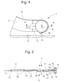
- 1 is a deflection area Escalator or an escalator referred to essentially a balustrade base 2, a balustrade 3 and a handrail 4.
- Escalator or an escalator referred to essentially a balustrade base 2, a balustrade 3 and a handrail 4.
- For the transport of People and objects are level 5 on an escalator or provided on a moving walk plates 5, each depending on of the cheek side reach the balustrade base 2.
- the Step side or plate side of the balustrade 3 is in further with transport side 6 and the outside of the Balustrade 3 designated 7.
- Balustrade 3 made, for example, of glass with a wall thickness of about 10 mm, which is the escalator or moving walk gives slim, light, elegant look.
- Fig. 1 shows a deflection of the handrail 4 by means of a about an axis 9 rotating, for example transparent Support disc 10, with a wall thickness that is about the Wall thickness of balustrade 3 corresponds.
- the axis 9 will of at least one, for example transparent Support cheek 11 held, for example, by means of a Welded connection 12 with the support structure of the Handrail 4 and / or for example by means of a screw or Rivet connection 13 is connected to the balustrade 3.
- the axis 9 is on the outside 7, for example by means of a screw or rivet connection 13 with the Carrier cheek 11 connected, like the carrying cheek 11 of the Transport side 6 by means of the welded connection 12 a support 14 of the handrail construction is connected. at transparent support cheeks 11 can be in the peripheral area Support disc 10 may be dark tinted.
- the ever support 14 arranged on one side of the support disk 10 has at one end a sliding surface 15 on which the handrail 4 slides and is guided on the outside. In the middle the handrail 4 carried by the rotatable support disc 10 and redirected.
- the support disc 10 is by means of a bearing 16 rotatably mounted on the axis 9.
- Fig. 3 shows the integrated in the balustrade base 2 Handrail drive 20 consisting of, for example Electric motor 21 by means of a chain 22 or by means of a belt 22 (toothed belt, V-belt, flat belt, Studded belt) drives a drive wheel 23.
- the support disc 10 is driven peripherally by the drive wheel 23.
- the Handrail 4 guided over a deflection wheel 24 is carried out Friction taken away from the support disc 10.
- the Electric motor 21 can be a torque motor or by means of of a control loop with a step chain 26.1 or one Step chain motor be synchronized.
- the section B-B shown in Fig. 4 illustrates the Arrangement of the handrail drive 20 in the balustrade base 2 and the peripheral, front-side drive of the support disk 10 by means of the drive wheel 23.
- the one with the Step chain 26.1 step 5 connected on both sides with the Rollers 25,26 shown on a on the structure 27th unroll the arranged guide 26.2.
- FIG. 5 and 6 show the one according to the invention Handrail drive 20 with an intermediate shaft 28, the Intermediate shaft 28 by means of a chain chain driving Main shaft 29 can be driven.
- the power transmission from Wave to wave or from the intermediate shaft 28 to one Transmission wheel 30 is made by means of chains 31 or belts 31 (Timing belts, V-belts, flat belts, nub belts), where the transmission wheel 30 drives the drive wheel 23.
- Fig. 6 shows the handrail drive 20 without transmission wheel 30, wherein the power transmission from the intermediate shaft 28 directly on the drive wheel 23 takes place by means of a crossed belt 32.
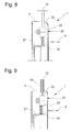
- Fig. 8 shows a drive wheel 23 with a smooth surface as Friction surface by means of which the support disk 10 can be driven.
- the drive wheel 23 is not on one, for example shown pendulum arm arranged by means of a Spring force of a spring 34 can be acted upon, the Drive wheel 23 is pressed against the support disk 10.
- the required contact pressure on the Friction contact point 33 generated.
- the Spring force of the spring 34 for example, pneumatically or can be hydraulically reinforced or weakened.
- Fig. 9 shows the drive wheel 23 with a smooth surface as Friction surface and the support plate 10 with a cord or Knurled or a cross knurled surface 35 as a friction surface
- the drive wheel 23, for example, a rubberized one Roll is made of polyurethane and is slim and therefore extremely light support plate 10 drives spring loaded. With the above surface of the support disc the friction at the friction contact point 33 improves and reduces the risk of slipping.
- Fig. 10 shows the drive wheel 23 with a Spur gear teeth 36, with the support disk 10 also has straight teeth.
- the Touch point 37 is located on the gear pitch circle and is form-fitting.
- the gears are with lots of little ones Teeth equipped because of damage to the handrail 4 would be given by large teeth.
- the inside of the Handrail 4 or the sliding position is due to the small Teeth on the large diameter of the support plate 10 hardly damaged.
- the handrail 4 is driven comparable to a multi-stage gear transmission, whereby the handrail 4 is engaged with the last gear.
- mounting bracket 38 holds that Drive wheel 23 at a certain distance from the support disc 10 fixed, the distance is adjustable.
Landscapes
- Escalators And Moving Walkways (AREA)
Abstract
Description
Es zeigen:
- Fig. 1
- eine Seitenansicht eines Umlenkbereiches einer Fahrtreppe,
- Fig. 2
- einen Schnitt entlang der Linie A-A des in Fig. 1 gezeigten Umlenkbereiches,
- Fig. 3
- eine Seitenansicht des Umlenkbereiches der Fahrtreppe mit Handlaufantrieb,
- Fig. 4
- einen Schnitt entlang der Linie B-B des in Fig. 3 gezeigten Umlenkbereiches,
- Fig. 5, Fig. 6
- Ausführungsvarianten des Handlaufantriebes mit Zwischenwelle,
- Fig. 7
- eine Ausführungsvariante des Handlaufantriebes ohne Zwischenwelle,
- Fig. 8, Fig. 9 und Fig. 10
- den Ausschnitt C der Fig. 4.
Claims (7)
- Fahrtreppe oder Fahrsteig bestehend aus einer Balustrade (3), einem Balustradensockel (2), Stufen (5) bzw. Platten (5) für den Transport von Personen und Gegenständen, einer an der Balustrade (3) angeordneten Handlaufkonstruktion mit einem Handlauf (4) für die Sicherheit der Personen, der in einem Umlenkbereich (1) der Balustrade (3) mittels einer antreibbaren Stützscheibe (10) umlenkbar ist,
dadurch gekennzeichnet, dass ein Handlaufantrieb (20) vorgesehen ist, der die Stützscheibe (10) peripher antreibt. - Fahrtreppe oder Fahrsteig nach Anspruch 1,
dadurch gekennzeichnet, dass der Handlaufantrieb (20) ein die Stützscheibe (10) antreibendes Antriebsrad (23) aufweist, wobei das Antriebsrad (23) ein Reibrad oder ein Zahnrad ist. - Fahrtreppe oder Fahrsteig nach Anspruch 1 oder nach Anspruch 2,
dadurch gekennzeichnet, dass der Handlaufantrieb (20) im Balustradensockel (2) angeordnet ist und einen regelbaren Motor (21) als Antrieb für das Antriebsrad (23) aufweist. - Fahrtreppe oder Fahrsteig nach Anspruch 1 oder nach Anspruch 2,
dadurch gekennzeichnet, dass das Antriebsrad (23) mittels einer eine Stufenkette (26.1) antreibenden Hauptwelle (29) antreibbar ist. - Fahrtreppe oder Fahrsteig nach einem der vorhergehenden Ansprüche,
dadurch gekennzeichnet, dass das Antriebsrad (23) eine glatte Oberfläche als Reibfläche und die Stützscheibe (10) eine Rändeloberfläche (35) als Reibfläche aufweisen. - Fahrtreppe oder Fahrsteig nach einem der vorhergehenden Ansprüche,
dadurch gekennzeichnet, dass das Antriebsrad (23) eine Stirnverzahnung (36) aufweist, die mit einer Verzahnung der Stützscheibe (10) in Eingriff steht. - Fahrtreppe oder Fahrsteig nach einem der vorhergehenden Ansprüche,
dadurch gekennzeichnet, dass die die Stützscheibe (10) tragenden, transparenten Tragwangen (11) im peripheren Bereich der Stützscheibe (10) eine Dunkeltönung aufweisen.
Priority Applications (1)
| Application Number | Priority Date | Filing Date | Title |
|---|---|---|---|
| EP20040008043 EP1468954B9 (de) | 2003-04-17 | 2004-04-02 | Handlaufantrieb für Fahrtreppe oder Fahrsteig |
Applications Claiming Priority (3)
| Application Number | Priority Date | Filing Date | Title |
|---|---|---|---|
| EP03405276 | 2003-04-17 | ||
| EP03405276 | 2003-04-17 | ||
| EP20040008043 EP1468954B9 (de) | 2003-04-17 | 2004-04-02 | Handlaufantrieb für Fahrtreppe oder Fahrsteig |
Publications (3)
| Publication Number | Publication Date |
|---|---|
| EP1468954A1 true EP1468954A1 (de) | 2004-10-20 |
| EP1468954B1 EP1468954B1 (de) | 2009-07-15 |
| EP1468954B9 EP1468954B9 (de) | 2009-09-16 |
Family
ID=32910147
Family Applications (1)
| Application Number | Title | Priority Date | Filing Date |
|---|---|---|---|
| EP20040008043 Expired - Lifetime EP1468954B9 (de) | 2003-04-17 | 2004-04-02 | Handlaufantrieb für Fahrtreppe oder Fahrsteig |
Country Status (1)
| Country | Link |
|---|---|
| EP (1) | EP1468954B9 (de) |
Citations (2)
| Publication number | Priority date | Publication date | Assignee | Title |
|---|---|---|---|---|
| US785882A (en) * | 1904-03-18 | 1905-03-28 | Edouard Louis Hocquart | Traveling staircase or the like. |
| DE19837914A1 (de) * | 1998-08-20 | 2000-03-02 | Otis Elevator Co | Vielpoliger Handlauf-Direktantrieb |
-
2004
- 2004-04-02 EP EP20040008043 patent/EP1468954B9/de not_active Expired - Lifetime
Patent Citations (2)
| Publication number | Priority date | Publication date | Assignee | Title |
|---|---|---|---|---|
| US785882A (en) * | 1904-03-18 | 1905-03-28 | Edouard Louis Hocquart | Traveling staircase or the like. |
| DE19837914A1 (de) * | 1998-08-20 | 2000-03-02 | Otis Elevator Co | Vielpoliger Handlauf-Direktantrieb |
Also Published As
| Publication number | Publication date |
|---|---|
| EP1468954B9 (de) | 2009-09-16 |
| EP1468954B1 (de) | 2009-07-15 |
Similar Documents
| Publication | Publication Date | Title |
|---|---|---|
| DE4238252C2 (de) | Zahn- und Keilriemeneinrichtung für Laufbänder | |
| DE60104139T2 (de) | Fahrtreppeantriebsmaschine mit treibriemen zum gleichzeitigen antrieb von handlauf und förderfläche | |
| EP1129923A2 (de) | Transportvorrichtung | |
| CA2464428C (en) | Handrail-drive for escalator or moving walk | |
| US5881859A (en) | Escalator handrail drive mechanism | |
| DE10063844B4 (de) | Antriebssystem für Rolltreppen und Rollsteige | |
| JP5334961B2 (ja) | 負荷分散型ハンドレール駆動装置 | |
| EP0599310B1 (de) | Riementrieb eines Torantriebs | |
| EP0599312A1 (de) | Riementrieb für einen Torantrieb | |
| AT502956B1 (de) | Muskelkraftbetriebenes fahrzeug, insbesondere stepproller | |
| DE4008061A1 (de) | Vorrichtung zum bewegen verschiebbarer teile | |
| EP1468954A1 (de) | Handlaufantrieb für fahrtreppe oder fahrsteig | |
| DE3732226A1 (de) | Doppelseitiger zahnriemen-fahrtreppenantrieb | |
| DE20100833U1 (de) | Fahrtreppe oder Fahrsteig | |
| WO2019029992A1 (de) | Handlauf-antriebssystem mit im handlauf integrierten antriebselementen | |
| DE68907212T2 (de) | Verbesserter drehzahlaenderer fuer eine motorisierte laufbandvorrichtung. | |
| DE10127587A1 (de) | Antriebseinrichtung für Rolltreppen bzw. Rollsteige | |
| DE1531120B1 (de) | Antrieb von Personenfoerderbaendern | |
| EP1464608B1 (de) | Handlaufantrieb für eine Fahrtreppe oder einen Fahrsteig | |
| EP2394946A1 (de) | Antriebsmechanismus für Antriebsketten von Rolltreppen und Rollsteigen | |
| DE10119478A1 (de) | Personenbeförderer mit einem von einem Antriebselement angetriebenen Riemenelement | |
| DE4111379A1 (de) | Foerdervorrichtung an seilfoerderanlagen zum antreiben von foerderseilen | |
| EP0560073A1 (de) | Trainingsgerät | |
| DE20204029U1 (de) | Fahrtreppe oder Fahrsteig | |
| DE1531120C (de) | Antrieb von Personenforderbandern |
Legal Events
| Date | Code | Title | Description |
|---|---|---|---|
| PUAI | Public reference made under article 153(3) epc to a published international application that has entered the european phase |
Free format text: ORIGINAL CODE: 0009012 |
|
| AK | Designated contracting states |
Kind code of ref document: A1 Designated state(s): AT BE BG CH CY CZ DE DK EE ES FI FR GB GR HU IE IT LI LU MC NL PL PT RO SE SI SK TR |
|
| AX | Request for extension of the european patent |
Extension state: AL HR LT LV MK |
|
| 17P | Request for examination filed |
Effective date: 20050413 |
|
| REG | Reference to a national code |
Ref country code: HK Ref legal event code: DE Ref document number: 1070042 Country of ref document: HK |
|
| AKX | Designation fees paid |
Designated state(s): AT CH CZ DE FR GB LI |
|
| 17Q | First examination report despatched |
Effective date: 20060803 |
|
| GRAP | Despatch of communication of intention to grant a patent |
Free format text: ORIGINAL CODE: EPIDOSNIGR1 |
|
| GRAS | Grant fee paid |
Free format text: ORIGINAL CODE: EPIDOSNIGR3 |
|
| GRAA | (expected) grant |
Free format text: ORIGINAL CODE: 0009210 |
|
| AK | Designated contracting states |
Kind code of ref document: B1 Designated state(s): AT CH CZ DE FR GB LI |
|
| REG | Reference to a national code |
Ref country code: CH Ref legal event code: EP Ref country code: GB Ref legal event code: FG4D Free format text: NOT ENGLISH |
|
| REF | Corresponds to: |
Ref document number: 502004009742 Country of ref document: DE Date of ref document: 20090827 Kind code of ref document: P |
|
| REG | Reference to a national code |
Ref country code: HK Ref legal event code: GR Ref document number: 1070042 Country of ref document: HK |
|
| PLBE | No opposition filed within time limit |
Free format text: ORIGINAL CODE: 0009261 |
|
| STAA | Information on the status of an ep patent application or granted ep patent |
Free format text: STATUS: NO OPPOSITION FILED WITHIN TIME LIMIT |
|
| 26N | No opposition filed |
Effective date: 20100416 |
|
| REG | Reference to a national code |
Ref country code: FR Ref legal event code: PLFP Year of fee payment: 13 |
|
| PGFP | Annual fee paid to national office [announced via postgrant information from national office to epo] |
Ref country code: CH Payment date: 20160426 Year of fee payment: 13 Ref country code: GB Payment date: 20160421 Year of fee payment: 13 Ref country code: CZ Payment date: 20160331 Year of fee payment: 13 |
|
| PGFP | Annual fee paid to national office [announced via postgrant information from national office to epo] |
Ref country code: AT Payment date: 20160421 Year of fee payment: 13 |
|
| REG | Reference to a national code |
Ref country code: FR Ref legal event code: PLFP Year of fee payment: 14 |
|
| PG25 | Lapsed in a contracting state [announced via postgrant information from national office to epo] |
Ref country code: CZ Free format text: LAPSE BECAUSE OF NON-PAYMENT OF DUE FEES Effective date: 20170402 |
|
| REG | Reference to a national code |
Ref country code: CH Ref legal event code: PL |
|
| REG | Reference to a national code |
Ref country code: AT Ref legal event code: MM01 Ref document number: 436465 Country of ref document: AT Kind code of ref document: T Effective date: 20170402 |
|
| GBPC | Gb: european patent ceased through non-payment of renewal fee |
Effective date: 20170402 |
|
| PG25 | Lapsed in a contracting state [announced via postgrant information from national office to epo] |
Ref country code: AT Free format text: LAPSE BECAUSE OF NON-PAYMENT OF DUE FEES Effective date: 20170402 |
|
| PG25 | Lapsed in a contracting state [announced via postgrant information from national office to epo] |
Ref country code: CH Free format text: LAPSE BECAUSE OF NON-PAYMENT OF DUE FEES Effective date: 20170430 Ref country code: GB Free format text: LAPSE BECAUSE OF NON-PAYMENT OF DUE FEES Effective date: 20170402 Ref country code: LI Free format text: LAPSE BECAUSE OF NON-PAYMENT OF DUE FEES Effective date: 20170430 |
|
| REG | Reference to a national code |
Ref country code: FR Ref legal event code: PLFP Year of fee payment: 15 |
|
| PGFP | Annual fee paid to national office [announced via postgrant information from national office to epo] |
Ref country code: DE Payment date: 20190418 Year of fee payment: 16 |
|
| PGFP | Annual fee paid to national office [announced via postgrant information from national office to epo] |
Ref country code: FR Payment date: 20190418 Year of fee payment: 16 |
|
| REG | Reference to a national code |
Ref country code: DE Ref legal event code: R119 Ref document number: 502004009742 Country of ref document: DE |
|
| PG25 | Lapsed in a contracting state [announced via postgrant information from national office to epo] |
Ref country code: DE Free format text: LAPSE BECAUSE OF NON-PAYMENT OF DUE FEES Effective date: 20201103 Ref country code: FR Free format text: LAPSE BECAUSE OF NON-PAYMENT OF DUE FEES Effective date: 20200430 |