EP1469152A1 - Rail - Google Patents
Rail Download PDFInfo
- Publication number
- EP1469152A1 EP1469152A1 EP04003102A EP04003102A EP1469152A1 EP 1469152 A1 EP1469152 A1 EP 1469152A1 EP 04003102 A EP04003102 A EP 04003102A EP 04003102 A EP04003102 A EP 04003102A EP 1469152 A1 EP1469152 A1 EP 1469152A1
- Authority
- EP
- European Patent Office
- Prior art keywords
- wall
- support
- web
- rail according
- support bracket
- Prior art date
- Legal status (The legal status is an assumption and is not a legal conclusion. Google has not performed a legal analysis and makes no representation as to the accuracy of the status listed.)
- Withdrawn
Links
- 210000002414 leg Anatomy 0.000 description 26
- 210000000689 upper leg Anatomy 0.000 description 2
- 238000010276 construction Methods 0.000 description 1
- 238000006073 displacement reaction Methods 0.000 description 1
- 239000000725 suspension Substances 0.000 description 1
Images


Classifications
-
- E—FIXED CONSTRUCTIONS
- E05—LOCKS; KEYS; WINDOW OR DOOR FITTINGS; SAFES
- E05D—HINGES OR SUSPENSION DEVICES FOR DOORS, WINDOWS OR WINGS
- E05D15/00—Suspension arrangements for wings
- E05D15/06—Suspension arrangements for wings for wings sliding horizontally more or less in their own plane
- E05D15/0621—Details, e.g. suspension or supporting guides
- E05D15/0626—Details, e.g. suspension or supporting guides for wings suspended at the top
- E05D15/0652—Tracks
-
- E—FIXED CONSTRUCTIONS
- E05—LOCKS; KEYS; WINDOW OR DOOR FITTINGS; SAFES
- E05Y—INDEXING SCHEME ASSOCIATED WITH SUBCLASSES E05D AND E05F, RELATING TO CONSTRUCTION ELEMENTS, ELECTRIC CONTROL, POWER SUPPLY, POWER SIGNAL OR TRANSMISSION, USER INTERFACES, MOUNTING OR COUPLING, DETAILS, ACCESSORIES, AUXILIARY OPERATIONS NOT OTHERWISE PROVIDED FOR, APPLICATION THEREOF
- E05Y2600/00—Mounting or coupling arrangements for elements provided for in this subclass
- E05Y2600/60—Mounting or coupling members; Accessories therefor
- E05Y2600/626—Plates or brackets
Definitions
- the invention relates to a mounting rail for carriages for hanging Sliding doors, gates, shutters or the like with a substantially C-shaped Cross-section, the horizontal web of the attachment serves a wall and its perpendicular flanges with each other pointing, at a distance from each other, horizontal bends are provided, which are designed as treads for the roles of the carriage.
- Such mounting rails are known. You will either be at a distance support angles lying apart or by means of a continuous Angle profile attached to a wall.
- the invention has for its object to fix the support rails of the type described above by means of supporting angles and thereby to reduce a low overall height the group consisting of the mounting rail and support brackets construction as well as to provide a uniform appearance, so that it is possible to dispense with additional avoidances.
- the solution to this problem by the invention is characterized in that the attachment is carried out by means of support brackets, the vertical leg of which is arranged between the wall and the wall-side flange and whose horizontal leg is fastened to the web.
- a profile piece corresponding at least to the thickness of the support bracket is formed with which the mounting rail is supported on the wall at the same time improved the mounting of the mounting rail.
- the front flange of the Carrier rail with an extension projecting beyond the web, which covers at least the end face of the horizontal leg of the support bracket.
- the extension can according to the invention with a cavity for receiving of the horizontal leg of the cover forming the support bracket be covered so that the horizontal leg of the support bracket as a whole becomes and is no longer visible.
- the attachment of the horizontal leg of the support bracket can be done according to a Feature of the invention done by at least one screw, the one Passes through hole in the web of the mounting rail.
- the thread for this screw can either in the web of the running rail or preferably in the horizontal Leg of the support bracket to be formed.
- the invention proposes lateral in the mounting rail Form cavities in which, for example, wire cables for driving the Wire rope deflections serving for carriages can be accommodated.
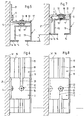
- the mounting rail 1 the carriages for hanging sliding doors, gates, Shutters or the like components has one essentially C-shaped cross section. It consists of a web 11 and a wall side Flange 12 and a front flange 13. At the ends of the flanges 12 and 13 bends 14 and 15 are provided, which are the treads for the roles of Form carriages.
- the mounting rails 1 are with mounting angles 2 spaced apart from one another attached to a wall W.
- Each support bracket consists of a vertical one Leg 21 and a horizontal leg 22.
- the mounting rail 1 is fastened to the horizontal Leg 22 of the support bracket 2 by means of a screw 3.
- the thread for this Screw 3 is preferably in a threaded hole in the horizontal leg 22 executed.
- the mounting rail 1 is mounted on the wall W as follows:
- At least two support brackets 2 are attached to the web 11 of the support rail 1 fastened by means of a screw 3 such that the vertical leg 21st the support bracket 2 points upwards, as in FIGS. 1 and 2 show.
- the mounting rail 1 is horizontal on the wall W aligned and pre-assembled using the wall screws 4, an amount x of the respective height of the fastening is to be deducted.
- the holes for the wall screws 4 in the wall W drilled.
- the screws 3 are then removed and the wall screws 4 loosened and the support bracket 2 rotated by 180 ° such that its vertical leg 21st now points downwards.
- the wall screws 4 Support bracket 2 attached.
- the mounting rail 1 with the screws 3 under the horizontal legs 22 of the support bracket 2 are screwed.
- the mounting rail 1 is therefore at the correct height on the wall W, which is around the amount x differs from the pre-assembly position.
- a profile piece 16 molded onto the wall-side flange 12 serves to additionally support the mounting rail 1 on the wall W.
- Flange 13 of the mounting rail 1 is provided with an extension 17, at least covers the end face of the horizontal leg 22. A sight of the Attachment of the mounting rail 1 serving mounting bracket 2 is thus out of the normal Viewing position impossible.
- the extension is 17th provided with a cover leg 19 pointing at right angles to the wall W, which together with the web 11 forms a cavity in which the horizontal Leg 22 of the support bracket 2 is arranged.
- one is from the bottom accessible screw 3 for fastening the mounting rail 1 to the mounting brackets 2 used.
- FIG. 9 also shows that the mounting rail 1 with the side in addition to the roles of the carriages formed cavities 6 can, in which wire ropes 7 are used for driving the carriage Wire rope deflections are housed.
Landscapes
- Engineering & Computer Science (AREA)
- Mechanical Engineering (AREA)
- Support Devices For Sliding Doors (AREA)
Applications Claiming Priority (2)
| Application Number | Priority Date | Filing Date | Title |
|---|---|---|---|
| DE20306219U | 2003-04-19 | ||
| DE20306219U DE20306219U1 (de) | 2003-04-19 | 2003-04-19 | Tragschiene |
Publications (1)
| Publication Number | Publication Date |
|---|---|
| EP1469152A1 true EP1469152A1 (fr) | 2004-10-20 |
Family
ID=7981578
Family Applications (1)
| Application Number | Title | Priority Date | Filing Date |
|---|---|---|---|
| EP04003102A Withdrawn EP1469152A1 (fr) | 2003-04-19 | 2004-02-12 | Rail |
Country Status (2)
| Country | Link |
|---|---|
| EP (1) | EP1469152A1 (fr) |
| DE (1) | DE20306219U1 (fr) |
Cited By (2)
| Publication number | Priority date | Publication date | Assignee | Title |
|---|---|---|---|---|
| EP3195773B1 (fr) * | 2014-12-03 | 2023-04-05 | Gebr. Willach GmbH | Porte coulissante en verre |
| EP4582658A1 (fr) | 2024-01-08 | 2025-07-09 | Griesser Holding AG | Dispositif de guidage de volet coulissant et volet coulissant le comprenant |
Families Citing this family (3)
| Publication number | Priority date | Publication date | Assignee | Title |
|---|---|---|---|---|
| DE20316490U1 (de) * | 2003-10-24 | 2004-01-08 | Hespe & Woelm Gmbh & Co. Kg | Aufhängevorrichtung für Schiebetüren |
| DE202004010518U1 (de) * | 2004-07-06 | 2004-09-09 | Hespe & Woelm Gmbh & Co. Kg | Tragschiene für Laufwagen zum Aufhängen von Schiebetüren, Toren, Fensterläden o.dgl. |
| FR3078736B1 (fr) * | 2018-03-12 | 2020-12-25 | Optimum | Ensemble de guidage pour battant d’une porte coulissante |
Citations (3)
| Publication number | Priority date | Publication date | Assignee | Title |
|---|---|---|---|---|
| US4476652A (en) * | 1981-08-05 | 1984-10-16 | Fermod | Device for suspending a slidable sealed door |
| FR2631072A1 (fr) * | 1988-05-04 | 1989-11-10 | Fermod | Dispositif de suspension de porte coulissante |
| US20020044824A1 (en) * | 2000-10-13 | 2002-04-18 | Hawa Ag | Fixing device for a rail |
Family Cites Families (2)
| Publication number | Priority date | Publication date | Assignee | Title |
|---|---|---|---|---|
| DE29906739U1 (de) | 1999-04-15 | 1999-07-08 | ABO System-Elemente GmbH, 42579 Heiligenhaus | Aufhängevorrichtung für ein verschiebbares Schließelement, insbesondere einen Schiebeladen, ein Schiebefenster, eine Schiebewand oder -tür, und eine Zwischenschiene hierfür |
| DE20204672U1 (de) | 2001-07-18 | 2002-07-11 | Hespe & Woelm GmbH & Co KG, 42579 Heiligenhaus | Halterung für eine langgestreckte Profilschiene aus einem nach unten hin offenen C-Profil |
-
2003
- 2003-04-19 DE DE20306219U patent/DE20306219U1/de not_active Expired - Lifetime
-
2004
- 2004-02-12 EP EP04003102A patent/EP1469152A1/fr not_active Withdrawn
Patent Citations (3)
| Publication number | Priority date | Publication date | Assignee | Title |
|---|---|---|---|---|
| US4476652A (en) * | 1981-08-05 | 1984-10-16 | Fermod | Device for suspending a slidable sealed door |
| FR2631072A1 (fr) * | 1988-05-04 | 1989-11-10 | Fermod | Dispositif de suspension de porte coulissante |
| US20020044824A1 (en) * | 2000-10-13 | 2002-04-18 | Hawa Ag | Fixing device for a rail |
Cited By (2)
| Publication number | Priority date | Publication date | Assignee | Title |
|---|---|---|---|---|
| EP3195773B1 (fr) * | 2014-12-03 | 2023-04-05 | Gebr. Willach GmbH | Porte coulissante en verre |
| EP4582658A1 (fr) | 2024-01-08 | 2025-07-09 | Griesser Holding AG | Dispositif de guidage de volet coulissant et volet coulissant le comprenant |
Also Published As
| Publication number | Publication date |
|---|---|
| DE20306219U1 (de) | 2003-06-12 |
Similar Documents
| Publication | Publication Date | Title |
|---|---|---|
| DE10338816B3 (de) | Halterung für eine Platte, insbesondere für eine Glasscheibe | |
| DE10329518B4 (de) | Führungseinrichtung für eine Schiebetür | |
| DE19733367A1 (de) | Flügel für eine Tür, ein Fenster oder dergleichen | |
| DE4323098A1 (de) | Dachreling für Fahrzeuge | |
| DE68911670T2 (de) | Beschlag für Schiebetüren. | |
| DE2844396A1 (de) | Schiebetuerschrank | |
| DE4335393A1 (de) | Blendeneinstellelement zur Neigungsverstellung der Frontplatte von Schubladen, Auszügen u. dgl. | |
| DE102014119145A1 (de) | Schiebetor und Baukastensystem für ein Schiebetor | |
| EP1469152A1 (fr) | Rail | |
| EP1568838A2 (fr) | Rail de guidage pour portes coulissantes ou portes coulissantes et pliantes | |
| DE2365225A1 (de) | Haengefoerderbahn | |
| DE3105277C2 (de) | Trennwand für Dusche | |
| EP1614843A2 (fr) | Rail de soutien pour chariots supportant des portes coulissantes, des portails, des volets ou similaires | |
| DE4229786C2 (de) | Sektionaltor oder Deckengliedertor | |
| EP0760416B1 (fr) | Portail coulissant | |
| DE69603523T2 (de) | Befestigungsvorrichtung am Deckenunterbau für tragende Geländerpfosten | |
| DE8115218U1 (de) | "schiebetuer fuer den einbau in eine maueraussparung o.dgl." | |
| DE9105425U1 (de) | Behängungsausbau für Frachtbehälter aller Art | |
| DE19935529C2 (de) | Befestigungsvorrichtung für die Laufschiene eines Fahrwerks | |
| DE29808586U1 (de) | Duschabtrennung | |
| DE20204495U1 (de) | Toranlage mit einem entlang mindestens eines ortsfesten Rollenbocks geführten Tragprofil | |
| DE102019120584A1 (de) | Beschlag für eine Schiebetür | |
| DE2821101A1 (de) | Moebel-auszugfuehrung | |
| EP3211162B1 (fr) | Système de porte coulissante | |
| DE29618677U1 (de) | Schiebebeschlag für Türen, Fenster o.dgl. |
Legal Events
| Date | Code | Title | Description |
|---|---|---|---|
| PUAI | Public reference made under article 153(3) epc to a published international application that has entered the european phase |
Free format text: ORIGINAL CODE: 0009012 |
|
| 17P | Request for examination filed |
Effective date: 20040820 |
|
| AK | Designated contracting states |
Kind code of ref document: A1 Designated state(s): AT BE BG CH CY CZ DE DK EE ES FI FR GB GR HU IE IT LI LU MC NL PT RO SE SI SK TR |
|
| AX | Request for extension of the european patent |
Extension state: AL LT LV MK |
|
| 17Q | First examination report despatched |
Effective date: 20050228 |
|
| AKX | Designation fees paid |
Designated state(s): AT BE BG CH CY CZ DE DK EE ES FI FR GB GR HU IE IT LI LU MC NL PT RO SE SI SK TR |
|
| RAP1 | Party data changed (applicant data changed or rights of an application transferred) |
Owner name: WOELM GESELLSCHAFT MIT BESCHRAENKTER HAFTUNG |
|
| STAA | Information on the status of an ep patent application or granted ep patent |
Free format text: STATUS: THE APPLICATION HAS BEEN WITHDRAWN |
|
| 18W | Application withdrawn |
Effective date: 20060131 |