EP1469183B1 - Steuervorrichtung für einen piezoelektrischen Ultraschallaktuator sowie Betriebsverfahren - Google Patents
Steuervorrichtung für einen piezoelektrischen Ultraschallaktuator sowie Betriebsverfahren Download PDFInfo
- Publication number
- EP1469183B1 EP1469183B1 EP04300205A EP04300205A EP1469183B1 EP 1469183 B1 EP1469183 B1 EP 1469183B1 EP 04300205 A EP04300205 A EP 04300205A EP 04300205 A EP04300205 A EP 04300205A EP 1469183 B1 EP1469183 B1 EP 1469183B1
- Authority
- EP
- European Patent Office
- Prior art keywords
- switch
- terminal
- voltage
- parallel
- piezo
- Prior art date
- Legal status (The legal status is an assumption and is not a legal conclusion. Google has not performed a legal analysis and makes no representation as to the accuracy of the status listed.)
- Expired - Lifetime
Links
- 238000000034 method Methods 0.000 title claims description 4
- 230000005284 excitation Effects 0.000 claims description 21
- 239000000446 fuel Substances 0.000 claims description 7
- 239000000919 ceramic Substances 0.000 claims description 6
- 239000003990 capacitor Substances 0.000 claims description 3
- 238000002604 ultrasonography Methods 0.000 claims 9
- 238000010586 diagram Methods 0.000 description 4
- 238000007599 discharging Methods 0.000 description 2
- 235000021183 entrée Nutrition 0.000 description 2
- 238000001914 filtration Methods 0.000 description 2
- 230000001939 inductive effect Effects 0.000 description 2
- 238000002347 injection Methods 0.000 description 2
- 239000007924 injection Substances 0.000 description 2
- 230000003321 amplification Effects 0.000 description 1
- 238000002485 combustion reaction Methods 0.000 description 1
- 230000008878 coupling Effects 0.000 description 1
- 238000010168 coupling process Methods 0.000 description 1
- 238000005859 coupling reaction Methods 0.000 description 1
- 238000002955 isolation Methods 0.000 description 1
- 238000011068 loading method Methods 0.000 description 1
- 238000003199 nucleic acid amplification method Methods 0.000 description 1
- 239000007921 spray Substances 0.000 description 1
- 230000002123 temporal effect Effects 0.000 description 1
- 238000009834 vaporization Methods 0.000 description 1
- 230000008016 vaporization Effects 0.000 description 1
Images


Classifications
-
- H—ELECTRICITY
- H02—GENERATION; CONVERSION OR DISTRIBUTION OF ELECTRIC POWER
- H02N—ELECTRIC MACHINES NOT OTHERWISE PROVIDED FOR
- H02N2/00—Electric machines in general using piezoelectric effect, electrostriction or magnetostriction
- H02N2/02—Electric machines in general using piezoelectric effect, electrostriction or magnetostriction producing linear motion, e.g. actuators; Linear positioners ; Linear motors
- H02N2/06—Drive circuits; Control arrangements or methods
- H02N2/065—Large signal circuits, e.g. final stages
- H02N2/067—Large signal circuits, e.g. final stages generating drive pulses
-
- F—MECHANICAL ENGINEERING; LIGHTING; HEATING; WEAPONS; BLASTING
- F02—COMBUSTION ENGINES; HOT-GAS OR COMBUSTION-PRODUCT ENGINE PLANTS
- F02D—CONTROLLING COMBUSTION ENGINES
- F02D41/00—Electrical control of supply of combustible mixture or its constituents
- F02D41/20—Output circuits, e.g. for controlling currents in command coils
- F02D41/2096—Output circuits, e.g. for controlling currents in command coils for controlling piezoelectric injectors
-
- F—MECHANICAL ENGINEERING; LIGHTING; HEATING; WEAPONS; BLASTING
- F02—COMBUSTION ENGINES; HOT-GAS OR COMBUSTION-PRODUCT ENGINE PLANTS
- F02D—CONTROLLING COMBUSTION ENGINES
- F02D41/00—Electrical control of supply of combustible mixture or its constituents
- F02D41/20—Output circuits, e.g. for controlling currents in command coils
- F02D2041/2003—Output circuits, e.g. for controlling currents in command coils using means for creating a boost voltage, i.e. generation or use of a voltage higher than the battery voltage, e.g. to speed up injector opening
- F02D2041/201—Output circuits, e.g. for controlling currents in command coils using means for creating a boost voltage, i.e. generation or use of a voltage higher than the battery voltage, e.g. to speed up injector opening by using a boost inductance
-
- F—MECHANICAL ENGINEERING; LIGHTING; HEATING; WEAPONS; BLASTING
- F02—COMBUSTION ENGINES; HOT-GAS OR COMBUSTION-PRODUCT ENGINE PLANTS
- F02D—CONTROLLING COMBUSTION ENGINES
- F02D41/00—Electrical control of supply of combustible mixture or its constituents
- F02D41/20—Output circuits, e.g. for controlling currents in command coils
- F02D2041/2003—Output circuits, e.g. for controlling currents in command coils using means for creating a boost voltage, i.e. generation or use of a voltage higher than the battery voltage, e.g. to speed up injector opening
- F02D2041/2013—Output circuits, e.g. for controlling currents in command coils using means for creating a boost voltage, i.e. generation or use of a voltage higher than the battery voltage, e.g. to speed up injector opening by using a boost voltage source
Definitions
- the present invention relates to a device for controlling an electrically controlled ultrasonic piezoelectric actuator, and more particularly to a piezoelectric stage fuel injector controlled by the electric injection computer of an internal combustion engine in a motor vehicle. It also relates to a method of implementing the device.
- an ultrasonic injector comprises, inter alia, a cylindrical nozzle supplied with fuel and at the end of which is provided an injection orifice, and means for cyclically vibrating the nozzle, such as a transducer, comprising a piezo ceramic stage.
- a piezoelectric injector ceramic is first-order equivalent to a capacitance whose charging voltage is high, greater than a hundred volts.
- the supply voltage is 12 or 42 volts, which involves increasing this voltage to ensure the charging and discharge of the ceramic.
- the first stage of generation of a high voltage is constituted by a first branch comprising a first inductor L 1 connected to a switching switch S 1 , mounted in antiparallel with a diode d 1 free wheel, and a second branch connected in parallel to the switching switch S 1 and comprising a diode D connected to a filtering capacitor C, one of the terminals of said diode D being connected to the junction point J 1 of the inductor L 1 and the switch S 1 of the first branch, the high supply voltage being delivered across the capacitor C.
- the second generation stage of a current source it is constituted by a branch comprising a second inductor L 2 connected to a switching switch S 2 mounted antiparallel with a diode d 2 freewheel, said inductor L 2 of value determined to achieve an oscillating circuit with each driven injector being connected on one side to the junction point J 2 of the diode D with the filtering capacity of the first stage and the other side to the switch S 2
- the document DE 196 32 872 A1 discloses a control device comprising a DC voltage source, a resonance inductance in series with a set of two branches in parallel, each comprising a first thyristor type switch, the two switches being mounted head to tail, connected by a point of junction with a diode mounted in antiparallel with the piezoelectric actuator, and a second thyristor type switch mounted in parallel with the set of two branches.
- the document DE 198 27 170 A1 proposes a control device which comprises a DC voltage source, a resonance inductance in series with a set of two branches in parallel, each comprising a first switch in series with a diode respectively, the two diodes being mounted head to tail, connected by a junction point to a diode mounted in antiparallel with the piezoelectric actuator.
- the object of the invention is to propose a new transformerless topology, simplified with respect to the prior art, having only one inductive element for generating an AC voltage across an injector from a source DC voltage.
- a first object of the invention is a device for controlling at least one ultrasonic piezoelectric actuator, electronically controlled from a control computer and a DC voltage source, the device being powered by the voltage source delivering a DC output voltage E between two extreme terminals B + and B - , and having, connected in parallel with said terminals, a resonance inductance L p in series with a set of two branches in parallel, each comprising a first switch P 11 and P 12 in series with a diode d 1 and d 2 respectively, the two diodes being mounted head to tail, connected by a junction point J to the actuator A i , characterized in that a second switch P 2 mounted anti-parallel with a diode D and delivering at its terminals a high-voltage alternating DC component serving as excitation voltage is connected in parallel to the actuator.
- the resonance inductance Lp is connected in series between the terminal B + of the voltage source and the set of two branches, itself connected by the junction point J to a first terminal of the second switch P 2 mounted in antiparallel with a diode D whose other terminal is connected to terminal B- of the voltage source, the actuator being connected in parallel between the junction point J and the terminal B-of the source.
- the resonance inductor Lp is connected in series between terminal B + of the voltage source and a first terminal of the second switch P 2 connected in anti-parallel with the diode D, whose second terminal is connected by the junction point J to a first terminal of the set of two branches whose other terminal is connected to the terminal B- of the voltage source, the actuator being mounted in parallel between the junction point between the inductance L p and the switch on the one hand and the junction point J on the other.
- the invention consists in generating a high-voltage sinusoidal signal, greater than a hundred volts, and a high frequency, greater than about ten kilohertz, on the piezoelectric cell of each fuel injector of a vehicle from a DC voltage source, ie the battery.
- a control device topology of an actuator ensuring the excitation of said piezoelectric ceramics, through an inductor to form a resonant circuit.
- These structures are valid from 1 to N injectors, N being an integer preferably equal to 4, 5, 6, 8, 10 or 12.
- the number of injectors ordered is 4 in the following description.
- the device for controlling a piezoelectric actuator A i is powered by a DC voltage source, such as an electric battery 12 Volts or 42 Volts of the vehicle, or a DC-DC converter, which delivers a DC voltage E between its two extreme terminals B- and B +.
- a DC voltage source such as an electric battery 12 Volts or 42 Volts of the vehicle, or a DC-DC converter, which delivers a DC voltage E between its two extreme terminals B- and B +.
- a resonance inductance L p in series with a set of two branches in parallel which each comprise a first switch P 11 and P 12 in series with a diode d 1 and d 2 respectively, these diodes being mounted head-to-tail relative to each other.
- junction point J of these two branches which is not connected to the inductance L p , is connected to a first terminal of a second switch P 2 , mounted in antiparallel with a diode D, and whose second terminal is connected to the terminal B- of the voltage source E.
- At least one actuator A i is mounted between the terminals of said second switch P 2 which delivers a high excitation alternating voltage V pi with a DC component.
- the resonance inductance L p is dimensioned so that its resonant frequency with the input capacitance of the piezoelectric actuator is greater than the frequency of recurrence of the switches, ie the ultrasonic piloting frequency of the piezoelectric injectors.
- the principle of operation of the device is based both on the reactive nature of the inductance L p and the selected actuator input impedance, as well as the fast charging and discharging of the piezoelectric by an inductance dimensioned so that its resonance with the input capacitance of the injector takes place at a frequency greater than the frequency of repetition of the desired voltage pattern.
- the cycle is repeated until another actuator is selected, for which the cycle will be the same.
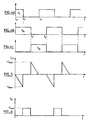
- Figure 4a shows the control signals of the second switch P 2 in anti-parallel with the diode D and Figures 4 b and 4 c illustrate the opening command signal and closing respectively of first switches P 11 and P 12 two branches in parallel.
- the current I LP increases in absolute value in the inductance L p up to a maximum value -I max of charge of the inductor and then drops sharply to the zero value at time t 1 of discharge start of the inductance in the actuator A i .
- the switch P 2 being open, the voltage V pi is zero across the actuator but at time t 1 it goes to the value V max for exciter.
- the switch P 12 is closed, the excitation voltage V pi becomes zero and the actuator A i discharges into the inductance L p , creating a current I LP in the inductor, of contrary to the charging current and maximum value + I max during step D).
- the voltage V pi is zero because the switch P 2 is closed.
- the inductance L p is connected in series between the terminal B + of the voltage source E and a first terminal of the second switch P 2 mounted in antiparallel. with the diode D, at the terminals of which is obtained the excitation voltage of the actuator selected.
- the second terminal is connected by the junction point J to a first terminal of the set of two branches whose other terminal is connected to the terminal B- of the voltage source.
- Actuator A is connected in parallel between the junction point J and the point connecting the inductance L p and the switch P 2 .
- FIG. 2 represents a device for controlling four piezoelectric ceramic actuators A 1 to A 4 connected in parallel across the switch P 2 , each piezoelectric actuator A 1 to A 4 being connected in series with a selection switch S 1 to S 4 , driven by the engine control computer which selects the piezoelectric injector to be excited.
- the switches of the two branches can be of the MOSFET type with intrinsic diode or of the IGBT or transistor type.
- One of the advantages of the invention is to propose a control topology of piezoelectric injectors which uses a reduced number of inductive components, in this case a single inductance which allows the fast loading and unloading of the piezoelectric washers. electric in relation to the frequency of repetition of the command.
Landscapes
- Engineering & Computer Science (AREA)
- Chemical & Material Sciences (AREA)
- Combustion & Propulsion (AREA)
- Mechanical Engineering (AREA)
- General Engineering & Computer Science (AREA)
- Fuel-Injection Apparatus (AREA)
- General Electrical Machinery Utilizing Piezoelectricity, Electrostriction Or Magnetostriction (AREA)
Claims (8)
- Vorrichtung zur Steuerung mindestens eines piezoelektrischen Ultraschallaktuators, der von einem Steuergerät und einer Gleichspannungsquelle elektronisch gesteuert wird, wobei die Vorrichtung von der Spannungsquelle versorgt wird, die zwischen zwei Endanschlüssen (B-, B+) eine Ausgangsgleichspannung (E) abgibt, und eine mit diesen Anschlüssen parallel geschaltete Resonanzinduktivität (Lp) umfasst, die mit einem Satz aus zwei parallel geschalteten zweigen in Reihe geschaltet ist, jeder umfassend einen ersten Schalter (P11 und P12), der jeweils mit einer Diode (d1 und d2) in Reihe geschaltet ist, wobei die zwei Dioden entgegengesetzt angeordnet sind, durch eine Verbindungsstelle (J) mit dem Aktor (Ai) verbunden sind, dadurch gekennzeichnet, dass ein zweiter Schalter (P2), der mit einer Diode (D) antiparallel geschaltet ist und an seinen Anschlüssen eine Wechselhochspannung mit Gleichstromkomponente abgibt, die als Erregungsspannung dient, mit dem Aktor parallelgeschaltet ist.
- Vorrichtung zur Steuerung mindestens eines piezoelektrischen Ultraschallaktuators nach Anspruch 1, dadurch gekennzeichnet, dass die Resonanzinduktivität (Lp) zwischen dem Anschluss (B+) der Spannungsquelle (E) und dem Satz der zwei Zweige in Reihe geschaltet ist, der seinerseits durch die Verbindungsstelle (J) mit einem ersten Anschluss des zweiten Schalters (P2) verbunden ist, der mit einer Diode (D) antiparallel geschaltet ist, deren anderer Anschluss mit dem Anschluss (B-) der Spannungsquelle verbunden ist, wobei der Aktor zwischen der Verbindungsstelle (J) und dem Anschluss (B-) der Quelle parallel geschaltet ist.
- Vorrichtung zur Steuerung mindestens eines piezoelektrischen Ultraschallaktuators nach Anspruch 1, dadurch gekennzeichnet, dass die Resonanzinduktivität (Lp) zwischen dem Anschluss (B+) der Spannungsquelle und einem ersten Anschluss des zweiten Schalters (P2) mit der Diode (D) antiparallel geschaltet ist, deren zweiter Anschluss durch die Verbindungsstelle (J) mit einem ersten Anschluss des Satzes der zwei Zweige verbunden ist, dessen anderer Anschluss mit dem Anschluss (B-) der Spannungsquelle verbunden ist, wobei der Aktor zwischen der Verbindungsstelle zwischen der Induktivität (Lp) und dem Schalter einerseits und der Verbindungsstelle (J) andererseits parallel geschaltet ist.
- Vorrichtung zur Steuerung mindestens eines piezoelektrischen Ultraschallaktuators nach einem der Ansprüche 1, 2 oder 3, dadurch gekennzeichnet, dass die Resonanzinduktivität (Lp) dimensioniert ist, damit ihre Resonanzfrequenz mit der Eingangskapazität des piezoelektrischen Aktors (Ai) größer ist als die Wiederholungsfrequenz der Schalter, das heißt, die Ultraschall-Steuerfrequenz der piezoelektrischen Einspritzdüsen.
- Vorrichtung zur Steuerung mindestens eines piezoelektrischen Ultraschallaktuators nach einem der Ansprüche 1 bis 4, dadurch gekennzeichnet, dass zur Steuerung der vier Aktoren aus piezoelektrischer Keramik (A1 bis A4) diese mit den Anschlüssen des zweiten Schalters (P2) parallel geschaltet sind, der mit der Diode (D) antiparallel geschaltet ist, wobei jeder mit einem vom elektronischen Motorsteuergerät gesteuerten Wählschalter (S1 bis S4) verbunden ist, der die Einspritzdüse wählt, die erregt werden soll, damit sie den Kraftstoff in den jeweiligen Zylinder einspritzt.
- Vorrichtung zur Steuerung mindestens eines piezoelektrischen Ultraschallaktuators nach einem der vorherigen Ansprüche, dadurch gekennzeichnet, dass die Gleichspannungsquelle eine 12 oder 42 Volt-Niederspannungsbatterie oder eine Lichtmaschine ist.
- Vorrichtung zur Steuerung mindestens eines piezoelektrischen Ultraschallaktuators nach einem der vorherigen Ansprüche, dadurch gekennzeichnet, dass der Schalter (P2), der eine Erregungsspannung (Vpi) an den mit seinen Anschlüssen verbundenen Aktor abgibt, vom Typ MOSFET mit eigenleitender Diode oder vom Typ IGBT oder Transistor ist.
- Verfahren zum Betreiben einer Vorrichtung zur Steuerung mindestens eines piezoelektrischen Ultraschallaktuators nach einem der Ansprüche 1 bis 6, dadurch gekennzeichnet, dass das Steuergerät die folgenden Schritte durchführt, um an den Anschlüssen der piezoelektrischen Einspritzdüse eine Wechselspannung mit Gleichstromkomponente zu erzeugen:- A) das gleichzeitige Schließen eines ersten Schalters (P11) eines Zweigs des Satzes, der mit der Resonanzinduktivität (Lp) verbunden ist, zum einen, und des zweiten Schalters (P2), der dazu bestimmt ist, eine Erregungsspannung an die Einspritzdüse abzugeben, zum anderen, damit der Strom (ILP) in die Induktivität fließt und die Energie in dieser gespeichert wird, während der andere erste Schalter (P12) des anderen Zweigs offen ist;- B) das Öffnen des zweiten Schalters (P2), während der erste Schalter (P11) eines Zweigs noch geschlossen ist und der (P12) des anderen Zweigs noch offen ist, damit der Strom (ILP) in der Induktivität in den gewählten Aktor (Ai) fließt und die Induktivität (Lp) mit der Eingangskapazität des Aktors in Resonanz tritt, der sich dadurch auf die Erregungsspannung (Vpi) lädt, die an den Anschlüssen des Schalters (P2) vorliegt;- C) das Öffnen des ersten Schalters (P11) des Zweigs, der geschlossen war, und das gleichzeitige Schließen des Schalters (P12) des anderen Zweigs, während der zweite Schalter (P2) offen bleibt, um den piezoelektrischen Aktor in die Induktivität (Lp) zu entladen, deren Strom (ILP) in entgegengesetzter Richtung zum Ladestrom zunimmt;- D) das Schließen des zweiten Schalters (P2), während einer der ersten Schalter der Zweige (P11) offen ist und der andere Schalter (P12) geschlossen ist;- E) das Öffnen des geschlossenen Schalters (P12) und Schließen des anderen, offenen Schalters (P11) der zwei Zweige, um in der Induktivität (Lp) Energie zu speichern.
Applications Claiming Priority (2)
| Application Number | Priority Date | Filing Date | Title |
|---|---|---|---|
| FR0304706A FR2854005B1 (fr) | 2003-04-15 | 2003-04-15 | Dispositif de commande d'actionneur piezo-electrique ultrasonore et son procede de mise en oeuvre |
| FR0304706 | 2003-04-15 |
Publications (2)
| Publication Number | Publication Date |
|---|---|
| EP1469183A1 EP1469183A1 (de) | 2004-10-20 |
| EP1469183B1 true EP1469183B1 (de) | 2007-06-20 |
Family
ID=32893369
Family Applications (1)
| Application Number | Title | Priority Date | Filing Date |
|---|---|---|---|
| EP04300205A Expired - Lifetime EP1469183B1 (de) | 2003-04-15 | 2004-04-14 | Steuervorrichtung für einen piezoelektrischen Ultraschallaktuator sowie Betriebsverfahren |
Country Status (3)
| Country | Link |
|---|---|
| EP (1) | EP1469183B1 (de) |
| DE (1) | DE602004007059T2 (de) |
| FR (1) | FR2854005B1 (de) |
Families Citing this family (3)
| Publication number | Priority date | Publication date | Assignee | Title |
|---|---|---|---|---|
| DE102007029957A1 (de) * | 2007-06-28 | 2009-01-02 | Robert Bosch Gmbh | Ultraschallsensor mit reziproker Sende- und Empfangsschaltung |
| FR2937196B1 (fr) * | 2008-10-14 | 2010-10-29 | Renault Sas | Dispositif et procede de commande d'un injecteur piezoelectrique ultrasonore resonant. |
| CN105790632B (zh) * | 2015-12-17 | 2017-12-12 | 中国矿业大学 | 柔性梁振动主动控制中压电作动器控制电压的标定装置及方法 |
Family Cites Families (3)
| Publication number | Priority date | Publication date | Assignee | Title |
|---|---|---|---|---|
| DE19632872C2 (de) * | 1996-08-14 | 1998-08-13 | Siemens Ag | Vorrichtung und Verfahren zum Ansteuern eines kapazitiven Stellgliedes |
| DE19734895C2 (de) * | 1997-08-12 | 2002-11-28 | Siemens Ag | Vorrichtung und Verfahren zum Ansteuern wenigstens eines kapazitiven Stellgliedes |
| DE19827170A1 (de) * | 1998-06-18 | 1999-12-23 | Bosch Gmbh Robert | Verfahren und Vorrichtung zum Steuern eines piezoelektrischen Elements auf eine wunschgemäße Ausdehnung |
-
2003
- 2003-04-15 FR FR0304706A patent/FR2854005B1/fr not_active Expired - Lifetime
-
2004
- 2004-04-14 DE DE602004007059T patent/DE602004007059T2/de not_active Expired - Lifetime
- 2004-04-14 EP EP04300205A patent/EP1469183B1/de not_active Expired - Lifetime
Non-Patent Citations (1)
| Title |
|---|
| None * |
Also Published As
| Publication number | Publication date |
|---|---|
| FR2854005B1 (fr) | 2005-06-24 |
| DE602004007059D1 (de) | 2007-08-02 |
| EP1469183A1 (de) | 2004-10-20 |
| FR2854005A1 (fr) | 2004-10-22 |
| DE602004007059T2 (de) | 2008-02-14 |
Similar Documents
| Publication | Publication Date | Title |
|---|---|---|
| EP2005491B1 (de) | Vorrichtung und verfahren zum antrieb von mehreren ultraschall-piezoaktoren | |
| WO2004001868A2 (fr) | Procede de pilotage electronique d’un dispositif de commande d’un actuateur piezo-electrique ultrasonore | |
| EP1446843A2 (de) | Elektronische steuervorrichtung für einen piezoelektrischen ultraschallaktuator und deren betriebsverfahren | |
| EP1469183B1 (de) | Steuervorrichtung für einen piezoelektrischen Ultraschallaktuator sowie Betriebsverfahren | |
| EP1067608B1 (de) | Anordnung und Steuerschaltung eines piezoelektrisches Antriebs | |
| WO2003038918A2 (fr) | Dispositif de commande d'un actuateur piezo-electrique | |
| WO2010043808A1 (fr) | Dispositif et procede de commande d'un injecteur piezo-electrique ultrasonore resonant | |
| FR2829314A1 (fr) | Dispositif de commande d'un actuateur piezo-electrique et son procede de mise en oeuvre | |
| EP1422764B1 (de) | Steuervorrichtung für einen piezoelektrischen Ultraschallaktuator und Betriebsverfahren | |
| EP1528605B1 (de) | Steuervorrichtung für piezoelektrische Ultraschallaktoren | |
| EP1471239A1 (de) | Steuervorrichtung für einen piezoelektrischen Ultraschallaktuator und Betriebsverfahren | |
| FR2923664A1 (fr) | Generateur de train d'impulsion de tension, application a la commande d'injecteur piozoelectrique ultrasonore. | |
| EP1276159B1 (de) | Ansteuerschaltung für einen piezoelektrischen Aktuator sowie Betriebsverfahren | |
| EP2024627A1 (de) | Vorrichtung zur steuerung eines piezoelektrischen ultraschallinjektors | |
| FR2879255A1 (fr) | Procede de pilotage electronique d'un actionneur piezo-electrique ultrasonore | |
| EP1828584B1 (de) | Vorrichtung zur elektronischen steuerung von piezoelektrischen ultraschallaktuatoren | |
| FR2851378A1 (fr) | Etage de puissance de sortie pour charges capacitives | |
| FR2861919A1 (fr) | Dispositif de commande de plusieurs actionneurs piezo-electriques ultrasonores | |
| FR2813455A1 (fr) | Dispositif de commande d'une ceramique piezo-electrique, notamment pour un actionneur d'injecteur de moteur a combustion interne | |
| FR2846485A1 (fr) | Dispositif de commande electronique d'un actionneur piezoelectrique ultrasonore | |
| FR2879256A1 (fr) | Dispositif de commande electronique d'actionneurs piezo-electriques | |
| FR2884368A1 (fr) | Convertisseur tension-tension comportant un circuit d'aide la commutation et procede de fonctionnement dudit convertisseur tension-tension |
Legal Events
| Date | Code | Title | Description |
|---|---|---|---|
| PUAI | Public reference made under article 153(3) epc to a published international application that has entered the european phase |
Free format text: ORIGINAL CODE: 0009012 |
|
| AK | Designated contracting states |
Kind code of ref document: A1 Designated state(s): AT BE BG CH CY CZ DE DK EE ES FI FR GB GR HU IE IT LI LU MC NL PL PT RO SE SI SK TR |
|
| AX | Request for extension of the european patent |
Extension state: AL HR LT LV MK |
|
| 17P | Request for examination filed |
Effective date: 20050415 |
|
| AKX | Designation fees paid |
Designated state(s): BE DE ES GB IT |
|
| RBV | Designated contracting states (corrected) |
Designated state(s): BE DE ES GB IT |
|
| GRAP | Despatch of communication of intention to grant a patent |
Free format text: ORIGINAL CODE: EPIDOSNIGR1 |
|
| GRAS | Grant fee paid |
Free format text: ORIGINAL CODE: EPIDOSNIGR3 |
|
| GRAA | (expected) grant |
Free format text: ORIGINAL CODE: 0009210 |
|
| AK | Designated contracting states |
Kind code of ref document: B1 Designated state(s): BE DE ES GB IT |
|
| REG | Reference to a national code |
Ref country code: GB Ref legal event code: FG4D Free format text: NOT ENGLISH |
|
| REF | Corresponds to: |
Ref document number: 602004007059 Country of ref document: DE Date of ref document: 20070802 Kind code of ref document: P |
|
| GBT | Gb: translation of ep patent filed (gb section 77(6)(a)/1977) |
Effective date: 20070802 |
|
| PG25 | Lapsed in a contracting state [announced via postgrant information from national office to epo] |
Ref country code: ES Free format text: LAPSE BECAUSE OF FAILURE TO SUBMIT A TRANSLATION OF THE DESCRIPTION OR TO PAY THE FEE WITHIN THE PRESCRIBED TIME-LIMIT Effective date: 20071001 |
|
| PLBE | No opposition filed within time limit |
Free format text: ORIGINAL CODE: 0009261 |
|
| STAA | Information on the status of an ep patent application or granted ep patent |
Free format text: STATUS: NO OPPOSITION FILED WITHIN TIME LIMIT |
|
| PG25 | Lapsed in a contracting state [announced via postgrant information from national office to epo] |
Ref country code: IT Free format text: LAPSE BECAUSE OF FAILURE TO SUBMIT A TRANSLATION OF THE DESCRIPTION OR TO PAY THE FEE WITHIN THE PRESCRIBED TIME-LIMIT Effective date: 20070620 |
|
| 26N | No opposition filed |
Effective date: 20080325 |
|
| BERE | Be: lapsed |
Owner name: RENAULT S.A.S. Effective date: 20080430 |
|
| PG25 | Lapsed in a contracting state [announced via postgrant information from national office to epo] |
Ref country code: BE Free format text: LAPSE BECAUSE OF NON-PAYMENT OF DUE FEES Effective date: 20080430 |
|
| PGFP | Annual fee paid to national office [announced via postgrant information from national office to epo] |
Ref country code: DE Payment date: 20170419 Year of fee payment: 14 Ref country code: GB Payment date: 20170419 Year of fee payment: 14 |
|
| REG | Reference to a national code |
Ref country code: DE Ref legal event code: R119 Ref document number: 602004007059 Country of ref document: DE |
|
| GBPC | Gb: european patent ceased through non-payment of renewal fee |
Effective date: 20180414 |
|
| PG25 | Lapsed in a contracting state [announced via postgrant information from national office to epo] |
Ref country code: DE Free format text: LAPSE BECAUSE OF NON-PAYMENT OF DUE FEES Effective date: 20181101 |
|
| PG25 | Lapsed in a contracting state [announced via postgrant information from national office to epo] |
Ref country code: GB Free format text: LAPSE BECAUSE OF NON-PAYMENT OF DUE FEES Effective date: 20180414 |