EP1469190A1 - Système d'alimentation en carburant sous haute pression - Google Patents
Système d'alimentation en carburant sous haute pression Download PDFInfo
- Publication number
- EP1469190A1 EP1469190A1 EP04008866A EP04008866A EP1469190A1 EP 1469190 A1 EP1469190 A1 EP 1469190A1 EP 04008866 A EP04008866 A EP 04008866A EP 04008866 A EP04008866 A EP 04008866A EP 1469190 A1 EP1469190 A1 EP 1469190A1
- Authority
- EP
- European Patent Office
- Prior art keywords
- fuel
- pressure
- pressure fuel
- supply control
- pump
- Prior art date
- Legal status (The legal status is an assumption and is not a legal conclusion. Google has not performed a legal analysis and makes no representation as to the accuracy of the status listed.)
- Withdrawn
Links
- 239000000446 fuel Substances 0.000 title claims abstract description 269
- 238000007599 discharging Methods 0.000 claims abstract description 47
- 239000002828 fuel tank Substances 0.000 claims description 10
- 238000002485 combustion reaction Methods 0.000 claims description 4
- 238000002347 injection Methods 0.000 abstract description 30
- 239000007924 injection Substances 0.000 abstract description 30
- 230000001105 regulatory effect Effects 0.000 description 2
- 230000003247 decreasing effect Effects 0.000 description 1
- 238000004519 manufacturing process Methods 0.000 description 1
- 230000004048 modification Effects 0.000 description 1
- 238000012986 modification Methods 0.000 description 1
- 230000002093 peripheral effect Effects 0.000 description 1
Images


Classifications
-
- F—MECHANICAL ENGINEERING; LIGHTING; HEATING; WEAPONS; BLASTING
- F02—COMBUSTION ENGINES; HOT-GAS OR COMBUSTION-PRODUCT ENGINE PLANTS
- F02M—SUPPLYING COMBUSTION ENGINES IN GENERAL WITH COMBUSTIBLE MIXTURES OR CONSTITUENTS THEREOF
- F02M39/00—Arrangements of fuel-injection apparatus with respect to engines; Pump drives adapted to such arrangements
- F02M39/005—Arrangements of fuel feed-pumps with respect to fuel injection apparatus
-
- F—MECHANICAL ENGINEERING; LIGHTING; HEATING; WEAPONS; BLASTING
- F02—COMBUSTION ENGINES; HOT-GAS OR COMBUSTION-PRODUCT ENGINE PLANTS
- F02M—SUPPLYING COMBUSTION ENGINES IN GENERAL WITH COMBUSTIBLE MIXTURES OR CONSTITUENTS THEREOF
- F02M59/00—Pumps specially adapted for fuel-injection and not provided for in groups F02M39/00 -F02M57/00, e.g. rotary cylinder-block type of pumps
- F02M59/20—Varying fuel delivery in quantity or timing
- F02M59/34—Varying fuel delivery in quantity or timing by throttling of passages to pumping elements or of overflow passages, e.g. throttling by means of a pressure-controlled sliding valve having liquid stop or abutment
-
- F—MECHANICAL ENGINEERING; LIGHTING; HEATING; WEAPONS; BLASTING
- F02—COMBUSTION ENGINES; HOT-GAS OR COMBUSTION-PRODUCT ENGINE PLANTS
- F02M—SUPPLYING COMBUSTION ENGINES IN GENERAL WITH COMBUSTIBLE MIXTURES OR CONSTITUENTS THEREOF
- F02M63/00—Other fuel-injection apparatus having pertinent characteristics not provided for in groups F02M39/00 - F02M57/00 or F02M67/00; Details, component parts, or accessories of fuel-injection apparatus, not provided for in, or of interest apart from, the apparatus of groups F02M39/00 - F02M61/00 or F02M67/00; Combination of fuel pump with other devices, e.g. lubricating oil pump
- F02M63/02—Fuel-injection apparatus having several injectors fed by a common pumping element, or having several pumping elements feeding a common injector; Fuel-injection apparatus having provisions for cutting-out pumps, pumping elements, or injectors; Fuel-injection apparatus having provisions for variably interconnecting pumping elements and injectors alternatively
- F02M63/0225—Fuel-injection apparatus having a common rail feeding several injectors ; Means for varying pressure in common rails; Pumps feeding common rails
-
- F—MECHANICAL ENGINEERING; LIGHTING; HEATING; WEAPONS; BLASTING
- F02—COMBUSTION ENGINES; HOT-GAS OR COMBUSTION-PRODUCT ENGINE PLANTS
- F02M—SUPPLYING COMBUSTION ENGINES IN GENERAL WITH COMBUSTIBLE MIXTURES OR CONSTITUENTS THEREOF
- F02M53/00—Fuel-injection apparatus characterised by having heating, cooling or thermally-insulating means
-
- F—MECHANICAL ENGINEERING; LIGHTING; HEATING; WEAPONS; BLASTING
- F02—COMBUSTION ENGINES; HOT-GAS OR COMBUSTION-PRODUCT ENGINE PLANTS
- F02M—SUPPLYING COMBUSTION ENGINES IN GENERAL WITH COMBUSTIBLE MIXTURES OR CONSTITUENTS THEREOF
- F02M59/00—Pumps specially adapted for fuel-injection and not provided for in groups F02M39/00 -F02M57/00, e.g. rotary cylinder-block type of pumps
- F02M59/02—Pumps specially adapted for fuel-injection and not provided for in groups F02M39/00 -F02M57/00, e.g. rotary cylinder-block type of pumps of reciprocating-piston or reciprocating-cylinder type
- F02M59/10—Pumps specially adapted for fuel-injection and not provided for in groups F02M39/00 -F02M57/00, e.g. rotary cylinder-block type of pumps of reciprocating-piston or reciprocating-cylinder type characterised by the piston-drive
- F02M59/102—Mechanical drive, e.g. tappets or cams
-
- F—MECHANICAL ENGINEERING; LIGHTING; HEATING; WEAPONS; BLASTING
- F02—COMBUSTION ENGINES; HOT-GAS OR COMBUSTION-PRODUCT ENGINE PLANTS
- F02M—SUPPLYING COMBUSTION ENGINES IN GENERAL WITH COMBUSTIBLE MIXTURES OR CONSTITUENTS THEREOF
- F02M63/00—Other fuel-injection apparatus having pertinent characteristics not provided for in groups F02M39/00 - F02M57/00 or F02M67/00; Details, component parts, or accessories of fuel-injection apparatus, not provided for in, or of interest apart from, the apparatus of groups F02M39/00 - F02M61/00 or F02M67/00; Combination of fuel pump with other devices, e.g. lubricating oil pump
- F02M63/0001—Fuel-injection apparatus with specially arranged lubricating system, e.g. by fuel oil
Definitions
- the present invention relates to a high-pressure fuel supplying apparatus wherein a fuel from a fuel tank is highly pressurized and supplied to a common-rail.
- an accumulating fuel injection apparatus using a common-rail is known.
- the accumulating fuel injection apparatus is comprised of a common-rail for accumulating a high-pressure fuel, an injector for injecting the high-pressure fuel accumulated in the common-rail, and a high-pressure fuel supplying apparatus for highly pressurizing a fuel from a fuel tank and supplying the fuel to the common-rail.
- the high-pressure fuel supplying apparatus is comprised of a low-pressure fuel supplying system having a feed pump for supplying the fuel from the fuel tank to a high-pressure pump, a fuel supply control system having a fuel supply control valve for adjusting the amount of fuel to be supplied from the feed pump to the high-pressure pump, and a high-pressure fuel discharging system having the high-pressure pump for pressurizing the regulated low-pressure fuel and discharging the high-pressure fuel to the common-rail.
- the low-pressure fuel supplying system, the fuel supply control system and the high-pressure fuel discharging system are integrally formed as a fuel injection pump. In the fuel injection pump, described below, the low-pressure fuel supplying system, the fuel supply control system and the high-pressure fuel discharging system are integrally provided.
- the high-pressure pump mounted on the fuel injection pump requires a large driving torque so as to pressurize the fuel to a high pressure.
- an internal-combustion engine hereinafter referred to as an engine
- the fuel injection pump is mounted directly to the engine or in the vicinity thereof.
- the feed pump, the fuel supply control valve, and the high-pressure pump, provided in the fuel injection pump are specially designed for the types or kinds of the fuel injection pump. Accordingly, the feed pump, the fuel supply control valve and the high-pressure pump are each expensive, thus resulting in an increase in the manufacturing cost of the fuel injection pump (high-pressure fuel supplying apparatus).
- the size of the low-pressure fuel supplying system, the size of the fuel supply control system and the size of the high-pressure fuel discharging system, independently from one another, can be reduced relative to the size of the fuel injection pump.
- the low-pressure fuel supplying system and the fuel supply control system have no restriction in mounting and they can be mounted in any empty space.
- the size of the integrally provided low-pressure fuel supplying system and fuel supply control system can be reduced relative to the fuel injection pump.
- the size of the separate high-pressure fuel discharging system can be reduced relative to the fuel injection pump.
- the integrally provided low-pressure fuel supplying system and fuel supply control system have no restriction in mounting, they can be mounted in any empty space.
- the fuel supply control valve of the high-pressure fuel supplying apparatus is an electromagnetic fuel supply control valve which opens/closes a fuel passage, for feeding the fuel to the high-pressure pump, in response to an electric signal.
- the fuel supply control valve By using the electromagnetic fuel supply control valve, which can be activated without using the output of the engine, the fuel supply control valve can be located in any place.
- the fuel supply control valve 6 controls the fuel amount to be fed to the high-pressure pump 2
- the fuel amount discharged from the high-pressure pump 2 is controlled, and the fuel pressure of the common-rail is controlled.
- the high-pressure pump 2 is comprised of one or a plurality of plunger pumps driven by the engine.
- a part of the fuel supplied to the high-pressure fuel discharging system 3 is supplied to a cam compartment 22 which surrounds the periphery of the cam ring 15 through an orifice 21, and surplus fuel in the cam compartment 22 is returned to the fuel tank 1 through the fuel pipe 23 for returning the fuel.
- the low-pressure fuel supplying system 5 the fuel supply control system 7 and the high-pressure fuel discharging system 3 are independently provided as separate pieces, and are connected by the fuel pipe 23.
- the size of the low-pressure fuel supplying system 5, the fuel supply control system 7 and the high-pressure fuel discharging system 3, independently from one another, can be reduced relative to the fuel injection pump.
- the high-pressure fuel discharging system 3 is smaller than the fuel injection pump, it is much easier to provide a space for mounting the high-pressure fuel discharging system 3 near the engine than to provide a space for mounting the fuel injection pump, which is hard to downsize, near the engine.
- the feed pump is driven by an electric motor, the feed pump 4 can be located at any place with no restriction. Also, use of the fuel supply control valve 6 in the form of an electromagnetic fuel supply control valve makes it possible to mount the fuel supply control valve 6 at any place.
- the mountability to a vehicle is extremely increased compared to the prior arts.
- general-purpose devices can be used for all (or some) of the feed pump 4, the fuel supply control valve 6 and the high-pressure pump 2.
- the total cost for the feed pump 4, the fuel supply control valve 6 and the high-pressure pump 2 can be kept low, and a low-price high-pressure fuel supplying apparatus can be provided.
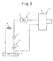
- the low-pressure fuel supplying system 5, the fuel supply control system 7 and the high-pressure fuel discharging system 3 are independently provided as separate pieces.
- the low-pressure fuel supplying system 5 and the fuel supply control system 7 are integrated to be a low-pressure fuel supply control system 24.
- the high-pressure fuel discharging system 3 is provided as a separate piece.
- the fuel supply control system 7 of the low-pressure fuel supply control system 24 is connected to the high-pressure fuel discharging system 3 by the fuel pipe 23.
- the low-pressure fuel supply control system 24 having, integral therewith, the low-pressure fuel supplying system 5 and the fuel supply control system 7 has no restriction in mounting, and it can be mounted in any empty space.
- the high-pressure fuel supplying apparatus of the second embodiment also has a good mountability to a vehicle, as in the first embodiment.
- general-purpose devices can be used for all (or some) of the feed pump 4, the fuel supply control valve 6 and the high-pressure pump 2.
- the total cost for the feed pump 4, the fuel supply control valve 6 and the high-pressure pump 2 can be kept low, and a low-price high-pressure fuel supplying apparatus can be provided.
- the fuel filter 9 is arranged on the suction side of the feed pump 4.
- the fuel filter 9 can be arranged between the feed pump 4 and the fuel supply control valve 6.
- the feed pump 4 is driven by the electric motor so that it can be mounted in any place.
- the feed pump 4 can be placed in that space and driven by the torque of the engine or the high-pressure pump 2 transmitted thereto through the power transmitting means such as a gear or a chain.
- a low-pressure fuel supplying system (5), a fuel supply control system (6) and a high-pressure fuel discharging system (3) are independently provided as separate pieces, and the low-pressure fuel supplying system (5), the fuel supply control system (7) and the high-pressure fuel discharging system (3) are connected by a fuel pipe.
- the high-pressure fuel discharging system (3) is small, relative to a fuel injection pump, it is easier to provide a space for mounting the high-pressure fuel discharging system (3) in the vicinity of the engine.
- the low-pressure fuel supplying system (5) and the fuel supply control system (7) have no restriction regarding mounting position, they can be mounted in any empty space in an engine room. Accordingly, the high-pressure fuel supplying apparatus has enhanced mountability on a vehicle.
Landscapes
- Engineering & Computer Science (AREA)
- Chemical & Material Sciences (AREA)
- Combustion & Propulsion (AREA)
- Mechanical Engineering (AREA)
- General Engineering & Computer Science (AREA)
- Fuel-Injection Apparatus (AREA)
Applications Claiming Priority (2)
| Application Number | Priority Date | Filing Date | Title |
|---|---|---|---|
| JP2003110261 | 2003-04-15 | ||
| JP2003110261A JP2004316518A (ja) | 2003-04-15 | 2003-04-15 | 高圧燃料供給装置 |
Publications (1)
| Publication Number | Publication Date |
|---|---|
| EP1469190A1 true EP1469190A1 (fr) | 2004-10-20 |
Family
ID=32906010
Family Applications (1)
| Application Number | Title | Priority Date | Filing Date |
|---|---|---|---|
| EP04008866A Withdrawn EP1469190A1 (fr) | 2003-04-15 | 2004-04-14 | Système d'alimentation en carburant sous haute pression |
Country Status (4)
| Country | Link |
|---|---|
| US (1) | US20040208753A1 (fr) |
| EP (1) | EP1469190A1 (fr) |
| JP (1) | JP2004316518A (fr) |
| CN (1) | CN1538053A (fr) |
Cited By (8)
| Publication number | Priority date | Publication date | Assignee | Title |
|---|---|---|---|---|
| EP1657434A1 (fr) * | 2004-11-12 | 2006-05-17 | C.R.F. Societa' Consortile per Azioni | Pompe à haute pression avec une installation pour régulation du débit pour un système d'injection de carburant |
| EP1674718A1 (fr) * | 2004-12-23 | 2006-06-28 | C.R.F. Società Consortile per Azioni | Système d'injection accumulateur pour moteur a combustion interne |
| EP1865193A1 (fr) * | 2006-06-09 | 2007-12-12 | CRF Societa'Consortile per Azioni | Dispositif d'injection de carburant pour un moteur à combustion interne |
| WO2009053364A1 (fr) * | 2007-10-26 | 2009-04-30 | Robert Bosch Gmbh | Système d'injection de carburant avec pompe à haute pression lubrifiée par le carburant, et unité de pompe associée |
| WO2011000599A1 (fr) * | 2009-06-30 | 2011-01-06 | Robert Bosch Gmbh | Système de carburant pour un moteur à combustion interne |
| EP2647824A1 (fr) * | 2012-04-05 | 2013-10-09 | Delphi Technologies Holding S.à.r.l. | Systèmes de pompe à injection et procédés de fonctionnement |
| ITMI20131923A1 (it) * | 2013-11-20 | 2015-05-21 | Bosch Gmbh Robert | Gruppo di pompaggio per alimentare combustibile, preferibilmente gasolio, da un serbatoio di contenimento ad un motore a combustione interna |
| CN109026470A (zh) * | 2018-09-04 | 2018-12-18 | 江苏农华智慧农业科技股份有限公司 | 一种上平衡轴插接输油泵的燃油高压供给系统 |
Families Citing this family (17)
| Publication number | Priority date | Publication date | Assignee | Title |
|---|---|---|---|---|
| JP3915718B2 (ja) * | 2003-03-11 | 2007-05-16 | 株式会社デンソー | 燃料供給ポンプ |
| JP4036197B2 (ja) * | 2003-04-03 | 2008-01-23 | 株式会社デンソー | 燃料供給ポンプ |
| DE102004002459A1 (de) * | 2004-01-16 | 2005-08-11 | Siemens Ag | Verfahren zur Einstellung der Fördermenge einer aus einem Kraftstofftank Kraftstoff ansaugenden Kraftstoffpumpeneinheit und Kraftstoffpumpeneinheit für das Verfahren |
| DE602005014283D1 (de) * | 2004-09-24 | 2009-06-10 | Denso Corp | Ventil zur Flusssteuerung |
| JP4450211B2 (ja) * | 2005-01-28 | 2010-04-14 | 株式会社デンソー | 燃料供給装置 |
| JP2008180208A (ja) * | 2006-12-27 | 2008-08-07 | Denso Corp | 燃料供給装置 |
| DE102007000855B4 (de) * | 2006-12-27 | 2020-06-10 | Denso Corporation | Kraftstofffördergerät und Speicherkraftstoffeinspritzsystem, das dieses aufweist |
| EP2063093A1 (fr) | 2007-11-26 | 2009-05-27 | Delphi Technologies, Inc. | Système d'injection de carburant |
| JP4475324B2 (ja) * | 2007-12-21 | 2010-06-09 | 株式会社デンソー | 燃料噴射ポンプ |
| ATE487053T1 (de) * | 2008-03-04 | 2010-11-15 | Magneti Marelli Spa | Common rail direkteinspritzanordnung mit einem absperrventil zur steuerung der förderung einer hochdruckkraftstoffpumpe |
| JP4930521B2 (ja) * | 2009-02-02 | 2012-05-16 | 株式会社デンソー | 燃料供給装置 |
| JP5267446B2 (ja) | 2009-12-22 | 2013-08-21 | 日産自動車株式会社 | 内燃機関の燃料供給装置 |
| DE102011089972A1 (de) * | 2011-12-27 | 2013-06-27 | Robert Bosch Gmbh | Kraftstoffüberströmventil für eine Kraftstoffeinspritzeinrichtung und Kraftstoffeinspritzeinrichtung mit Kraftstoffüberströmventil |
| JP5459330B2 (ja) * | 2012-01-31 | 2014-04-02 | 株式会社デンソー | 燃料供給ポンプ |
| ITMI20120892A1 (it) * | 2012-05-23 | 2013-11-24 | Bosch Gmbh Robert | Valvola di troppo pieno e impianto di iniezione di combustibile per un motore a combustione interna comprednente detta valvola di troppo pieno, |
| CN103807064B (zh) * | 2014-01-26 | 2017-05-10 | 奇瑞汽车股份有限公司 | 一种光学发动机的供油系统 |
| CN108862180B (zh) * | 2018-07-05 | 2024-03-08 | 珠海格力智能装备有限公司 | 供料系统 |
Citations (5)
| Publication number | Priority date | Publication date | Assignee | Title |
|---|---|---|---|---|
| EP0299337A2 (fr) * | 1987-07-08 | 1989-01-18 | IVECO FIAT S.p.A. | Système d'injection de carburant pour un moteur à combustion interne |
| DE4444417A1 (de) * | 1994-12-14 | 1996-06-20 | Bosch Gmbh Robert | Kraftstoffversorgungsanlage |
| EP0853194A2 (fr) * | 1996-12-23 | 1998-07-15 | ELASIS SISTEMA RICERCA FIAT NEL MEZZOGIORNO Società Consortile per Azioni | Dispositif de pompage pour transférer du carburant d'un réservoir vers un moteur à combustion interne |
| US6142747A (en) * | 1998-03-13 | 2000-11-07 | Robert Bosch Gmbh | Fuel pump assembly |
| EP1298316A2 (fr) * | 2001-09-26 | 2003-04-02 | DEUTZ Aktiengesellschaft | Système d'injection de carburant |
Family Cites Families (5)
| Publication number | Priority date | Publication date | Assignee | Title |
|---|---|---|---|---|
| JP2689226B2 (ja) * | 1994-12-02 | 1997-12-10 | 株式会社ゼクセル | 高圧燃料噴射装置用燃料ポンプ |
| KR100237535B1 (ko) * | 1996-02-29 | 2000-01-15 | 나까무라 히로까즈 | 내연기관용 연료공급장치 |
| DE19612412B4 (de) * | 1996-03-28 | 2006-07-06 | Siemens Ag | Regelung für ein Druckfluid-Versorgungssystem, insbesondere für den Hochdruck in einem Kraftstoff-Einspritzsystem |
| US6024064A (en) * | 1996-08-09 | 2000-02-15 | Denso Corporation | High pressure fuel injection system for internal combustion engine |
| FR2763100B1 (fr) * | 1997-05-09 | 1999-07-23 | Magneti Marelli France | By-pass de delestage pour pompe a injection directe a haute pression |
-
2003
- 2003-04-15 JP JP2003110261A patent/JP2004316518A/ja not_active Withdrawn
-
2004
- 2004-04-05 US US10/816,898 patent/US20040208753A1/en not_active Abandoned
- 2004-04-14 EP EP04008866A patent/EP1469190A1/fr not_active Withdrawn
- 2004-04-15 CN CNA2004100343845A patent/CN1538053A/zh active Pending
Patent Citations (5)
| Publication number | Priority date | Publication date | Assignee | Title |
|---|---|---|---|---|
| EP0299337A2 (fr) * | 1987-07-08 | 1989-01-18 | IVECO FIAT S.p.A. | Système d'injection de carburant pour un moteur à combustion interne |
| DE4444417A1 (de) * | 1994-12-14 | 1996-06-20 | Bosch Gmbh Robert | Kraftstoffversorgungsanlage |
| EP0853194A2 (fr) * | 1996-12-23 | 1998-07-15 | ELASIS SISTEMA RICERCA FIAT NEL MEZZOGIORNO Società Consortile per Azioni | Dispositif de pompage pour transférer du carburant d'un réservoir vers un moteur à combustion interne |
| US6142747A (en) * | 1998-03-13 | 2000-11-07 | Robert Bosch Gmbh | Fuel pump assembly |
| EP1298316A2 (fr) * | 2001-09-26 | 2003-04-02 | DEUTZ Aktiengesellschaft | Système d'injection de carburant |
Cited By (14)
| Publication number | Priority date | Publication date | Assignee | Title |
|---|---|---|---|---|
| EP1657434A1 (fr) * | 2004-11-12 | 2006-05-17 | C.R.F. Societa' Consortile per Azioni | Pompe à haute pression avec une installation pour régulation du débit pour un système d'injection de carburant |
| US7263979B2 (en) | 2004-11-12 | 2007-09-04 | C.R.F. Societa Consortile Per Azioni | High-pressure pump with a device for regulating the flow rate for a fuel-injection system |
| EP1674718A1 (fr) * | 2004-12-23 | 2006-06-28 | C.R.F. Società Consortile per Azioni | Système d'injection accumulateur pour moteur a combustion interne |
| US7228844B2 (en) | 2004-12-23 | 2007-06-12 | C.R.F. Societa Consortile Per Azioni | Internal combustion engine storage-volume fuel injection system |
| EP1865193A1 (fr) * | 2006-06-09 | 2007-12-12 | CRF Societa'Consortile per Azioni | Dispositif d'injection de carburant pour un moteur à combustion interne |
| US7395812B2 (en) | 2006-06-09 | 2008-07-08 | C.R.F. Societa Consortile Per Azioni | Fuel-injection system for an internal-combustion engine |
| WO2009053364A1 (fr) * | 2007-10-26 | 2009-04-30 | Robert Bosch Gmbh | Système d'injection de carburant avec pompe à haute pression lubrifiée par le carburant, et unité de pompe associée |
| WO2011000599A1 (fr) * | 2009-06-30 | 2011-01-06 | Robert Bosch Gmbh | Système de carburant pour un moteur à combustion interne |
| RU2556470C2 (ru) * | 2009-06-30 | 2015-07-10 | Роберт Бош Гмбх | Система питания двигателя внутреннего сгорания |
| EP2647824A1 (fr) * | 2012-04-05 | 2013-10-09 | Delphi Technologies Holding S.à.r.l. | Systèmes de pompe à injection et procédés de fonctionnement |
| ITMI20131923A1 (it) * | 2013-11-20 | 2015-05-21 | Bosch Gmbh Robert | Gruppo di pompaggio per alimentare combustibile, preferibilmente gasolio, da un serbatoio di contenimento ad un motore a combustione interna |
| WO2015074878A1 (fr) * | 2013-11-20 | 2015-05-28 | Robert Bosch Gmbh | Unité de pompage pour alimentation en carburant, de préférence en carburant diesel, depuis un réservoir de stockage vers un moteur à combustion interne |
| US10190553B2 (en) | 2013-11-20 | 2019-01-29 | Robert Bosch Gmbh | Pumping unit for feeding fuel, preferably diesel fuel, from a storage tank to an internal combustion engine |
| CN109026470A (zh) * | 2018-09-04 | 2018-12-18 | 江苏农华智慧农业科技股份有限公司 | 一种上平衡轴插接输油泵的燃油高压供给系统 |
Also Published As
| Publication number | Publication date |
|---|---|
| CN1538053A (zh) | 2004-10-20 |
| US20040208753A1 (en) | 2004-10-21 |
| JP2004316518A (ja) | 2004-11-11 |
Similar Documents
| Publication | Publication Date | Title |
|---|---|---|
| EP1469190A1 (fr) | Système d'alimentation en carburant sous haute pression | |
| KR100373616B1 (ko) | 고압 연료 펌프 및 고압 연료 펌프용 캠 | |
| US7044110B2 (en) | Fuel injection device for a combustion engine | |
| US7219654B2 (en) | Fuel injection device for an internal combustion engine | |
| US8205596B2 (en) | Fuel injection device for an internal combustion engine | |
| US7118350B2 (en) | Radial piston pump | |
| US6848423B2 (en) | Fuel injection system for an internal combustion engine | |
| US20110209687A1 (en) | High-pressure fuel pump for an internal combustion engine | |
| US9422897B2 (en) | Fuel system for an internal combustion engine | |
| US7128054B2 (en) | Fuel injection system for an internal combustion engine | |
| US6976473B2 (en) | Fuel injection system for an internal combustion engine | |
| JP4475324B2 (ja) | 燃料噴射ポンプ | |
| US7077107B2 (en) | Fuel-injection device for an internal combustion engine | |
| JP2002155824A (ja) | 内燃機関のための燃料供給装置 | |
| US6959694B2 (en) | Fuel injection system for an internal combustion engine | |
| US20050241616A1 (en) | Fuel injection device for an internal combustion engine | |
| US7850435B2 (en) | Fuel injection device for an internal combustion engine | |
| US20030010319A1 (en) | Fuel injection device | |
| US6966301B2 (en) | Accumulator fuel system | |
| JP4787444B2 (ja) | ラジアルピストンポンプ | |
| JP2001329926A (ja) | 燃料噴射システム | |
| US7406936B2 (en) | Accumulator fuel system | |
| JP4640387B2 (ja) | 高圧ポンプおよび内燃機関の燃料供給装置 | |
| JP4329755B2 (ja) | 内燃機関の高圧燃料ポンプ | |
| JP2007211653A (ja) | 内燃機関用燃料噴射装置 |
Legal Events
| Date | Code | Title | Description |
|---|---|---|---|
| PUAI | Public reference made under article 153(3) epc to a published international application that has entered the european phase |
Free format text: ORIGINAL CODE: 0009012 |
|
| AK | Designated contracting states |
Kind code of ref document: A1 Designated state(s): AT BE BG CH CY CZ DE DK EE ES FI FR GB GR HU IE IT LI LU MC NL PL PT RO SE SI SK TR |
|
| AX | Request for extension of the european patent |
Extension state: AL HR LT LV MK |
|
| 17P | Request for examination filed |
Effective date: 20041112 |
|
| 17Q | First examination report despatched |
Effective date: 20050208 |
|
| AKX | Designation fees paid |
Designated state(s): DE FR IT |
|
| STAA | Information on the status of an ep patent application or granted ep patent |
Free format text: STATUS: THE APPLICATION HAS BEEN WITHDRAWN |
|
| 18W | Application withdrawn |
Effective date: 20060126 |