EP1469209A2 - Kabelverbindung und Betätigungsgehäuse - Google Patents
Kabelverbindung und Betätigungsgehäuse Download PDFInfo
- Publication number
- EP1469209A2 EP1469209A2 EP04009225A EP04009225A EP1469209A2 EP 1469209 A2 EP1469209 A2 EP 1469209A2 EP 04009225 A EP04009225 A EP 04009225A EP 04009225 A EP04009225 A EP 04009225A EP 1469209 A2 EP1469209 A2 EP 1469209A2
- Authority
- EP
- European Patent Office
- Prior art keywords
- sleeve
- isolator
- cable
- opening
- housing
- Prior art date
- Legal status (The legal status is an assumption and is not a legal conclusion. Google has not performed a legal analysis and makes no representation as to the accuracy of the status listed.)
- Granted
Links
- 239000004033 plastic Substances 0.000 claims abstract description 13
- 229920003023 plastic Polymers 0.000 claims abstract description 13
- 229910000831 Steel Inorganic materials 0.000 claims abstract description 10
- 239000010959 steel Substances 0.000 claims abstract description 10
- 230000000284 resting effect Effects 0.000 claims description 2
- 230000033001 locomotion Effects 0.000 description 9
- 230000005540 biological transmission Effects 0.000 description 7
- 239000002184 metal Substances 0.000 description 7
- 239000004677 Nylon Substances 0.000 description 3
- 230000000712 assembly Effects 0.000 description 3
- 238000000429 assembly Methods 0.000 description 3
- 238000002788 crimping Methods 0.000 description 3
- 229920001778 nylon Polymers 0.000 description 3
- 238000002955 isolation Methods 0.000 description 2
- 230000008878 coupling Effects 0.000 description 1
- 238000010168 coupling process Methods 0.000 description 1
- 238000005859 coupling reaction Methods 0.000 description 1
- 229920001971 elastomer Polymers 0.000 description 1
- 239000000945 filler Substances 0.000 description 1
- 239000000446 fuel Substances 0.000 description 1
- 239000011521 glass Substances 0.000 description 1
- 239000000463 material Substances 0.000 description 1
- 239000002991 molded plastic Substances 0.000 description 1
- 229920002635 polyurethane Polymers 0.000 description 1
- 239000004814 polyurethane Substances 0.000 description 1
- 239000012858 resilient material Substances 0.000 description 1
- 239000005060 rubber Substances 0.000 description 1
- 229920002379 silicone rubber Polymers 0.000 description 1
- 239000004945 silicone rubber Substances 0.000 description 1
- 238000004804 winding Methods 0.000 description 1
Images



Classifications
-
- F—MECHANICAL ENGINEERING; LIGHTING; HEATING; WEAPONS; BLASTING
- F16—ENGINEERING ELEMENTS AND UNITS; GENERAL MEASURES FOR PRODUCING AND MAINTAINING EFFECTIVE FUNCTIONING OF MACHINES OR INSTALLATIONS; THERMAL INSULATION IN GENERAL
- F16C—SHAFTS; FLEXIBLE SHAFTS; ELEMENTS OR CRANKSHAFT MECHANISMS; ROTARY BODIES OTHER THAN GEARING ELEMENTS; BEARINGS
- F16C1/00—Flexible shafts; Mechanical means for transmitting movement in a flexible sheathing
- F16C1/26—Construction of guiding-sheathings or guiding-tubes
- F16C1/262—End fittings; Attachment thereof to the sheathing or tube
- F16C1/265—End fittings; Attachment thereof to the sheathing or tube with a swivel tube connected to the end-fitting of a sheathing, e.g. with a spherical joint
-
- F—MECHANICAL ENGINEERING; LIGHTING; HEATING; WEAPONS; BLASTING
- F16—ENGINEERING ELEMENTS AND UNITS; GENERAL MEASURES FOR PRODUCING AND MAINTAINING EFFECTIVE FUNCTIONING OF MACHINES OR INSTALLATIONS; THERMAL INSULATION IN GENERAL
- F16C—SHAFTS; FLEXIBLE SHAFTS; ELEMENTS OR CRANKSHAFT MECHANISMS; ROTARY BODIES OTHER THAN GEARING ELEMENTS; BEARINGS
- F16C1/00—Flexible shafts; Mechanical means for transmitting movement in a flexible sheathing
- F16C1/10—Means for transmitting linear movement in a flexible sheathing, e.g. "Bowden-mechanisms"
- F16C1/102—Arrangements to mount end fittings of the sheathings to support walls or brackets
-
- F—MECHANICAL ENGINEERING; LIGHTING; HEATING; WEAPONS; BLASTING
- F16—ENGINEERING ELEMENTS AND UNITS; GENERAL MEASURES FOR PRODUCING AND MAINTAINING EFFECTIVE FUNCTIONING OF MACHINES OR INSTALLATIONS; THERMAL INSULATION IN GENERAL
- F16C—SHAFTS; FLEXIBLE SHAFTS; ELEMENTS OR CRANKSHAFT MECHANISMS; ROTARY BODIES OTHER THAN GEARING ELEMENTS; BEARINGS
- F16C2361/00—Apparatus or articles in engineering in general
- F16C2361/61—Toothed gear systems, e.g. support of pinion shafts
-
- F—MECHANICAL ENGINEERING; LIGHTING; HEATING; WEAPONS; BLASTING
- F16—ENGINEERING ELEMENTS AND UNITS; GENERAL MEASURES FOR PRODUCING AND MAINTAINING EFFECTIVE FUNCTIONING OF MACHINES OR INSTALLATIONS; THERMAL INSULATION IN GENERAL
- F16C—SHAFTS; FLEXIBLE SHAFTS; ELEMENTS OR CRANKSHAFT MECHANISMS; ROTARY BODIES OTHER THAN GEARING ELEMENTS; BEARINGS
- F16C2361/00—Apparatus or articles in engineering in general
- F16C2361/65—Gear shifting, change speed gear, gear box
-
- F—MECHANICAL ENGINEERING; LIGHTING; HEATING; WEAPONS; BLASTING
- F16—ENGINEERING ELEMENTS AND UNITS; GENERAL MEASURES FOR PRODUCING AND MAINTAINING EFFECTIVE FUNCTIONING OF MACHINES OR INSTALLATIONS; THERMAL INSULATION IN GENERAL
- F16H—GEARING
- F16H61/00—Control functions within control units of change-speed- or reversing-gearings for conveying rotary motion ; Control of exclusively fluid gearing, friction gearing, gearings with endless flexible members or other particular types of gearing
- F16H61/26—Generation or transmission of movements for final actuating mechanisms
- F16H61/36—Generation or transmission of movements for final actuating mechanisms with at least one movement being transmitted by a cable
-
- Y—GENERAL TAGGING OF NEW TECHNOLOGICAL DEVELOPMENTS; GENERAL TAGGING OF CROSS-SECTIONAL TECHNOLOGIES SPANNING OVER SEVERAL SECTIONS OF THE IPC; TECHNICAL SUBJECTS COVERED BY FORMER USPC CROSS-REFERENCE ART COLLECTIONS [XRACs] AND DIGESTS
- Y10—TECHNICAL SUBJECTS COVERED BY FORMER USPC
- Y10T—TECHNICAL SUBJECTS COVERED BY FORMER US CLASSIFICATION
- Y10T74/00—Machine element or mechanism
- Y10T74/20—Control lever and linkage systems
- Y10T74/20396—Hand operated
- Y10T74/20402—Flexible transmitter [e.g., Bowden cable]
-
- Y—GENERAL TAGGING OF NEW TECHNOLOGICAL DEVELOPMENTS; GENERAL TAGGING OF CROSS-SECTIONAL TECHNOLOGIES SPANNING OVER SEVERAL SECTIONS OF THE IPC; TECHNICAL SUBJECTS COVERED BY FORMER USPC CROSS-REFERENCE ART COLLECTIONS [XRACs] AND DIGESTS
- Y10—TECHNICAL SUBJECTS COVERED BY FORMER USPC
- Y10T—TECHNICAL SUBJECTS COVERED BY FORMER US CLASSIFICATION
- Y10T74/00—Machine element or mechanism
- Y10T74/20—Control lever and linkage systems
- Y10T74/20396—Hand operated
- Y10T74/20402—Flexible transmitter [e.g., Bowden cable]
- Y10T74/2045—Flexible transmitter [e.g., Bowden cable] and sheath support, connector, or anchor
Definitions
- Motion-transmitting remote control cable assemblies are used for transmitting both force and motion along a curved path in aircraft, automotive, and marine environments.
- Known cable assemblies can be used for transmitting load and motion in both push and pull type applications.
- typical applications include but are not limited to parking brakes, accelerators, hood releases, brake releases, trunk releases, park lock, tilt wheel controls, fuel filler doors, transmission shifter cables, and hydraulic control cables.
- One specific use of such remote control cable assemblies is positioning transmission shift members in automobiles.
- These cables include an inner core wire used to execute the actuation motion, and an outer case held stationary.
- the outer case typically includes a liner tube and a wire windings around the tube creating a strong case, which is then coated with nylon to provide an outer covering.
- This invention concerns connectors for shift cables used to operate automatic transmissions, four wheel drive transfer cases, etc., by movement of a shift lever in the driver's compartment.
- the shift lever is usually connected to various linkage components contained in a shifter housing including a base housing and a cover. Such connections must prevent moisture from entering the housing and the transmission of sound and vibrations to the housing, as well as to establish a mechanical coupling of the operating cable thereto.
- a connector was separately assembled to the cable, and then the connector was assembled to the shifter base housing. This separate assembly necessitated a separate seal to the housing and a number of other manually installed components to couple the connector to the base housing in addition to the components necessary to isolate and seal the connector to the cable, which added components created significant labor and component costs.
- An elastomeric isolator enclosing one end of a metal sleeve is inserted into a generally cylindrical bore in the protrusion from the outside of the housing, abutted against shoulders form in the inside of the protrusion bore, the isolator is also formed with an integral partially spherical seat which is abutted against a ball end of the swivel tube.
- a cap is installed in place over the end of the protrusion compressing the protruding end of the isolator, the cap having one or more wing features snap fit over an exterior shoulder on the housing protrusion to capture and hold these components in position.
- the isolator provides a moisture seal and sound vibration isolation between the housing and the connector and the cable to minimize the number of components, which also may be very quickly assembled to the housing base to connect and seal the cable thereto.
- the isolator is assembled or overmolded onto the one end of the metal steel sleeve to enclose the same, a flanged tubular plastic insert also previously molded or assembled to the end of the steel sleeve, forming a single unitary piece.
- the base housing is formed with an internal tubular protrusion configured to receive a swivel tube inserted from outside the housing, the swivel tube having a ball end which comes to rest in a partially spherical seat molded into the protrusion when the swivel tube is inserted into a concentric hole aligned with the seat, the hole allowing the body of the swivel tube to pass into the interior of the base housing.
- the metal sleeve is crimped to an operator cable case, while the cable core wire passes through the sleeve, through a guide opening in the plastic tube insert, and thence through a hole in the partially spherical seat in the isolator which holds the ball end of the swivel against the partially spherical seat molded into the housing protrusion.
- the cable core wire also extends through the swivel tube and is fixed to one end of a rod to be connected to linkage components driven by a shift lever, which rod is slidably received in the other end of the swivel tube.
- a cable shifter housing assembly 10 includes an operator cable 12 and base housing member 14.
- the cable 12 has a fitting assembly 16 for connection to a vehicle drive unit to be controlled (not shown), including an end piece 18 received on a control element of the unit to be controlled.
- the cable 12 includes an outer case 20 and a core wire 22 which moves within the case 20 to carry out the actuating movement required to operate the controlled unit, in the well known manner.
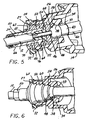
- the cable 12 is secured to the base housing 14 by an integrated connector-isolator assembly 24 fit within a generally cylindrical opening 56 ( Figure 5) over a protrusion 26 of the base housing 14.
- the base housing 14 is installed in the vehicle passenger compartment and houses a steel shift rod 28 having an eye 30 at its free end to be able to be connected to various linkage components (not shown) enclosed within the base housing 14 and moved by a control lever (also not shown) accessible in the passenger compartment so that the driver can operate the controlled unit.
- a cover would normally overlie the interior of the base housing 14, secured to housing flange 32.
- FIG. 2 shows further details of the integrated connector isolator assembly 24.
- the base housing 14 which may be constructed of a suitable molded structural plastic, such as a glass filled nylon, includes the generally cylindrical protrusion 26 which functions as an integrated cable connector housing.
- An inner projecting tube portion 34 has a partially spherical seat 38 concentric to a central bore through which the body 42 of a plastic swivel tube 40 passes in extending into the interior space 44 of the base housing 14.
- a reduced diameter land 43 of the body 42 is provided to increase clearance with a flared wall 39 and to increase the spherical area of the ball head 48 of the swivel tube 40.
- the partially spherical seat 38 engages the generally spherical ball head 48 of the swivel tube 40 integral with the body 42 to prevent movement of the swivel tube 40 into the interior space 44 of the basing housing 14 while allowing a limited tilting of the rod 28 which is slidably fit therein to accommodate the lengthwise movement induced by movement of the connected linkage components.
- a flared wall 39 around the seat 38 accommodates the tilting of the swivel rod 40 to increase the extent of tilting possible.
- the cable core wire 22 passes through an opening 46 in the swivel tube 40 with a generous clearance to avoid contact therewith, and the end extends into a hole in the end of the rod 28, in which it is fixedly connected as by a crimping or staking at the inserted end of the rod 28.
- the swivel tube 40 provides lateral support for the rod 28 as it undergoes telescoping sliding movement therein and limited tilting caused by operation of the linkage components (not shown).
- a metal sleeve 50 has an isolator 52 assembled over one end of the sleeve 50 to enclose the same.
- a plastic flanged tubular insert 54 is molded or assembled to the same one end of the sleeve 50 lining the inside of the one end of the sleeve 50.
- the one end of the sleeve 50 is inserted into a generally cylindrical opening 56 of the housing protrusion 26 after the addition of the isolator 52 and insert 54.
- the generally cylindrical opening 56 has two steps or shoulders 58, 60 and a tapered shoulder 62 molded therein against which are abutted corresponding features on the isolator 52.
- the isolator 52 may be molded in two or more transverse sectional parts to enable easy assembly over the flanges on the sleeve 50 and insert 54. Alternatively, the isolator 52 may be overmolded to the one end of the sleeve 50.
- the metal sleeve 50 is typically made of steel and has an intermediate flange 64 which acts to transmit the thrust exerted by the outer casing 20 when the cable 12 is operated into the isolator 52.
- the flange on the plastic tubular insert 54 also assists in this.
- the isolator 52 is designed to absorb any sound or vibrations transmitted along the cable 12 to prevent these from reaching the base housing 14 in the known manner, and also acts as a seal, and thus is constructed of a resilient material such as polyurethane, rubber, silicone rubber or similar materials.
- a hardness on the order of Shore A 50-60 is desirable to provide sufficient stiffness to hold the case 20 of the cable 12 while elastic enough to seal to the sleeve 50 and housing 14 and to absorb any sound or vibrations.
- the sleeve 50 is secured to the case 20 of the cable 12 as by hex crimping the ribbed end 66 to the case 20 in the known manner as depicted in Figure 6.
- a flange 49 on the sleeve 50 acts as a stop to locate the cable case 20 endwise when inserted therein prior to crimping.
- the isolator 52 is formed with a partially spherical seat 68 which captures the ball end 48 of the swivel tube 40, by abutting the same when the isolator 52 is inserted into the opening 56.
- the isolator 52 and metal sleeve 50 are inserted from the left as viewed in the drawings into the opening 56.
- the end face 70 of the isolator 52 projects slightly past the end 27 of the housing protrusion ( Figure 7).
- a snap cap 72 is then advanced onto a reduced diameter section 53 ( Figure 7) of the isolator 52 to compress the same slightly until wings 74 snap over a sloping ridge 76 to catch on the perpendicular rear face thereof. This secures the assemblage of these parts together.
- the isolator 52 acts as a seal against both the housing 14 and sleeve 50, as well as a sound/vibration isolator preventing transmission of sound or vibrations between the sleeve 50 and housing 14.
- the snap cap 72 is constructed of a molded plastic such as unfilled nylon to be strong enough to hold the parts together yet able to be deflected to be snap fit over the ridge 76.
- the cable 12 and base housing 14 form a single assembly, reducing the possibility of dislodgement, loosening or moisture leakage into the housing 14 while eliminating extra seals and other components necessary if the cable and connector 24 were assembled together separately from the housing 14.
- the isolator 52 end portion 53 protrudes through the hole 73 in the snap cap 72 to insure that no direct contact with the metal sleeve 50 occurs, assuring complete isolation between the sleeve 50 and housing 14 to prevent transmission of sound and vibration thereto.
- the plastic insert 54 has an aligned passage 55 which acts as a guide for the cable wire core 22, without causing undue wear as the wire core 22 is shifted back and forth to operate the transmission. There is sufficient clearance within the swivel tube 40 to insure minimal contact therewith to minimize wear.
- the swivel tube 40 is inserted into the housing through the bore 56 of the housing protrusion 26, the ball end 48 resting on the seat 38.
- the sleeve-isolator assemblage is then inserted into bore 56 and the cap 72 installed by snap fitting onto the protrusion 26.
- the cable 12 is then inserted to abut the case 20 against the flange 49, with the wire core 22 then advanced through the sleeve 50, insert 54 through the swivel tube 40, and the end thereof inserted into a hole in one end of the steel rod 28.
- the cable wire core 22 crimped or staked thereto or otherwise fixedly attached to the rod 28.
- the steel rod 20 is slid into the swivel tube 40 as the wire core 22 is retracted, the cable case 20 thereafter crimped to the steel sleeve 50.
Landscapes
- Engineering & Computer Science (AREA)
- General Engineering & Computer Science (AREA)
- Health & Medical Sciences (AREA)
- Oral & Maxillofacial Surgery (AREA)
- Mechanical Engineering (AREA)
- Flexible Shafts (AREA)
- Cable Accessories (AREA)
- Fluid-Damping Devices (AREA)
- Installation Of Indoor Wiring (AREA)
- Arrangement Or Mounting Of Control Devices For Change-Speed Gearing (AREA)
- Gear-Shifting Mechanisms (AREA)
- Details Of Connecting Devices For Male And Female Coupling (AREA)
Applications Claiming Priority (2)
| Application Number | Priority Date | Filing Date | Title |
|---|---|---|---|
| US46348903P | 2003-04-17 | 2003-04-17 | |
| US463489P | 2003-04-17 |
Publications (3)
| Publication Number | Publication Date |
|---|---|
| EP1469209A2 true EP1469209A2 (de) | 2004-10-20 |
| EP1469209A3 EP1469209A3 (de) | 2005-12-07 |
| EP1469209B1 EP1469209B1 (de) | 2010-08-18 |
Family
ID=32908755
Family Applications (1)
| Application Number | Title | Priority Date | Filing Date |
|---|---|---|---|
| EP04009225A Expired - Lifetime EP1469209B1 (de) | 2003-04-17 | 2004-04-19 | Kabelverbindung und Betätigungsgehäuse |
Country Status (4)
| Country | Link |
|---|---|
| US (1) | US7770489B2 (de) |
| EP (1) | EP1469209B1 (de) |
| AT (1) | ATE478266T1 (de) |
| DE (1) | DE602004028687D1 (de) |
Cited By (7)
| Publication number | Priority date | Publication date | Assignee | Title |
|---|---|---|---|---|
| US7353728B2 (en) * | 2004-08-31 | 2008-04-08 | Dura Global Technologies, Inc. | Conduit end fitting |
| WO2009128834A1 (en) * | 2008-04-18 | 2009-10-22 | Dura Global Technologies, Inc. | Transmission cable assembly for high temperature environments |
| WO2010068847A3 (en) * | 2008-12-12 | 2010-09-16 | Dura Global Technologies, Inc. | Cable assembly with retainer |
| CN101876371A (zh) * | 2009-05-01 | 2010-11-03 | 杜拉环球技术公司 | 换档拉索组件及用于该换档拉索组件的连接器 |
| US8857289B2 (en) | 2007-04-11 | 2014-10-14 | Dura Operating, Llc | Transmission cable assembly for high temperature environments |
| CN105240523A (zh) * | 2015-11-02 | 2016-01-13 | 重庆御捷汽车部件有限公司 | 带减震、减摩和过盈密封结构的汽车拉索 |
| CN105240522A (zh) * | 2015-11-02 | 2016-01-13 | 重庆御捷汽车部件有限公司 | 带减震和过盈密封结构的汽车拉索 |
Families Citing this family (10)
| Publication number | Priority date | Publication date | Assignee | Title |
|---|---|---|---|---|
| US7117740B2 (en) * | 2005-01-10 | 2006-10-10 | Honeywell International, Inc. | Remote visual liquid quantity indicator |
| US20060236804A1 (en) * | 2005-04-26 | 2006-10-26 | Ruhlander Gregory P | Shifter base with integrated receptacle for cable adjust assembly |
| US7753166B2 (en) * | 2005-12-08 | 2010-07-13 | Windsor Machine & Stamping Ltd | Resonant frequency adjustor and method of utilizing the same |
| US7465282B2 (en) | 2006-05-18 | 2008-12-16 | Schukra Of North America, Ltd. | Easy install hinge connection |
| US8245379B2 (en) * | 2007-10-24 | 2012-08-21 | Dura Global Technologies, Llc | Snap-together, two-piece guide tube for a push-pull cable assembly |
| GB0919682D0 (en) | 2009-11-11 | 2009-12-23 | Hi Lex Cable System Company Ltd | Damper |
| DE102013220409A1 (de) * | 2013-10-10 | 2015-04-16 | Zf Friedrichshafen Ag | Befestigungseinrichtung, Wählhebelgehäuse, Kraftübertragungselement, Schaltvorrichtung und Verfahren zum Befestigen einer Schaltvorrichtung |
| WO2017079446A1 (en) | 2015-11-03 | 2017-05-11 | Schlage Lock Company Llc | Adjustable length cable |
| KR102692280B1 (ko) * | 2019-03-25 | 2024-08-05 | 현대자동차주식회사 | 차량 도난 방지 장치 |
| USD1021826S1 (en) * | 2020-03-12 | 2024-04-09 | Tornatech Inc. | Mechanical activator for electrical contactor in a fire pump controller |
Citations (1)
| Publication number | Priority date | Publication date | Assignee | Title |
|---|---|---|---|---|
| US5884531A (en) | 1996-11-27 | 1999-03-23 | Dura Automotive Systems, Inc. | Low lash rotating conduit end fitting for a remote control cable assembly that isolates against vibration/noise transmission |
Family Cites Families (14)
| Publication number | Priority date | Publication date | Assignee | Title |
|---|---|---|---|---|
| US3101821A (en) * | 1958-04-09 | 1963-08-27 | Mcculloch Corp | Motor control |
| US4034622A (en) * | 1976-06-17 | 1977-07-12 | Caterpillar Tractor Co. | Infinitely adjustable cable controlled apparatus and method |
| US4348348A (en) * | 1980-06-23 | 1982-09-07 | Teleflex Incorporated | Method for making a remote control assembly with vibration dampener |
| US4793050A (en) * | 1986-07-14 | 1988-12-27 | Teleflex Incorporated | Remote control assembly with improved isolator |
| US5347882A (en) * | 1993-09-07 | 1994-09-20 | Fki Industries Inc. | Cable mounting construction |
| US5448926A (en) * | 1993-11-03 | 1995-09-12 | Teleflex Incorporated | Remote control assembly with vibration dampener |
| JPH07208443A (ja) * | 1994-01-25 | 1995-08-11 | Toyoda Gosei Co Ltd | ケーブルの案内支持部材 |
| US5662004A (en) * | 1995-01-19 | 1997-09-02 | Grand Haven Stamped Products, Div. Of Jsj Corporation | Vehicle shift cable connection |
| US5862710A (en) * | 1996-11-27 | 1999-01-26 | Dura Automotive Systems, Inc. | Zero lash joint for a rotating conduit fitting for a remote control cable assembly |
| ES2117956B1 (es) * | 1996-12-03 | 1999-04-01 | Fico Cables Sa | Terminal de funda para cables de mando. |
| IT1292041B1 (it) * | 1997-05-30 | 1999-01-25 | Brambilla Cornelia | Disposizione di aggancio rapipo di un comando a distanza mediante cavi flessibili singoli o plurimi |
| DE19946372A1 (de) * | 1998-11-16 | 2000-05-18 | United Parts Fhs Automobil Sys | Schnellbefestiger mit Drehfeder |
| US6119543A (en) * | 1999-06-01 | 2000-09-19 | Teleflex Incorporated | Swivel insert remote control assembly and method of making same |
| DE20115326U1 (de) * | 2001-09-17 | 2001-11-29 | United Parts FHS Automobil Systeme GmbH, 37586 Dassel | Schnellbefestiger |
-
2004
- 2004-04-16 US US10/826,133 patent/US7770489B2/en active Active
- 2004-04-19 AT AT04009225T patent/ATE478266T1/de not_active IP Right Cessation
- 2004-04-19 EP EP04009225A patent/EP1469209B1/de not_active Expired - Lifetime
- 2004-04-19 DE DE602004028687T patent/DE602004028687D1/de not_active Expired - Lifetime
Patent Citations (1)
| Publication number | Priority date | Publication date | Assignee | Title |
|---|---|---|---|---|
| US5884531A (en) | 1996-11-27 | 1999-03-23 | Dura Automotive Systems, Inc. | Low lash rotating conduit end fitting for a remote control cable assembly that isolates against vibration/noise transmission |
Cited By (10)
| Publication number | Priority date | Publication date | Assignee | Title |
|---|---|---|---|---|
| US7353728B2 (en) * | 2004-08-31 | 2008-04-08 | Dura Global Technologies, Inc. | Conduit end fitting |
| US8857289B2 (en) | 2007-04-11 | 2014-10-14 | Dura Operating, Llc | Transmission cable assembly for high temperature environments |
| WO2009128834A1 (en) * | 2008-04-18 | 2009-10-22 | Dura Global Technologies, Inc. | Transmission cable assembly for high temperature environments |
| WO2010068847A3 (en) * | 2008-12-12 | 2010-09-16 | Dura Global Technologies, Inc. | Cable assembly with retainer |
| CN102256833A (zh) * | 2008-12-12 | 2011-11-23 | 杜拉环球技术有限责任公司 | 具有保持器的缆索组件 |
| US8141454B2 (en) | 2008-12-12 | 2012-03-27 | Dura Automotive Systems, Llc | Cable assembly with retainer |
| CN102256833B (zh) * | 2008-12-12 | 2014-07-23 | 杜拉环球技术有限责任公司 | 具有保持器的缆索组件 |
| CN101876371A (zh) * | 2009-05-01 | 2010-11-03 | 杜拉环球技术公司 | 换档拉索组件及用于该换档拉索组件的连接器 |
| CN105240523A (zh) * | 2015-11-02 | 2016-01-13 | 重庆御捷汽车部件有限公司 | 带减震、减摩和过盈密封结构的汽车拉索 |
| CN105240522A (zh) * | 2015-11-02 | 2016-01-13 | 重庆御捷汽车部件有限公司 | 带减震和过盈密封结构的汽车拉索 |
Also Published As
| Publication number | Publication date |
|---|---|
| ATE478266T1 (de) | 2010-09-15 |
| EP1469209B1 (de) | 2010-08-18 |
| DE602004028687D1 (de) | 2010-09-30 |
| US20040255712A1 (en) | 2004-12-23 |
| EP1469209A3 (de) | 2005-12-07 |
| US7770489B2 (en) | 2010-08-10 |
Similar Documents
| Publication | Publication Date | Title |
|---|---|---|
| US7770489B2 (en) | Integrated cable connection and shifter housing | |
| US5884531A (en) | Low lash rotating conduit end fitting for a remote control cable assembly that isolates against vibration/noise transmission | |
| US8146455B2 (en) | Reverse clip cap terminal connector | |
| US5806139A (en) | Grommet assembly | |
| US6748820B2 (en) | Self-adjusting isolator for reducing cable lash in transmission shift systems | |
| EP0775840B1 (de) | Verbindungs- und Verstellvorrichtung für zwei Teile eines Bowdenzuges und Verfahren zum Zusammenbau | |
| JP4518950B2 (ja) | ボーデンケーブルのシース用アンカー手段 | |
| EP0651165B1 (de) | Feinbedienungseinrichtung mit Schwingungsdämpfer | |
| EP0753676B1 (de) | Bowdenzugvorrichtung | |
| US20090120231A1 (en) | Cable assembly | |
| US5862710A (en) | Zero lash joint for a rotating conduit fitting for a remote control cable assembly | |
| US7597027B2 (en) | Isolator for a motion transmitting remote control assembly | |
| WO1998023875A9 (en) | Zero lash joint for a rotating conduit fitting for a remote control cable assembly | |
| US7353728B2 (en) | Conduit end fitting | |
| US4419641A (en) | Solenoid | |
| EP2220386B1 (de) | Verbindungsvorrichtung für ein getriebekabel in einem fahrzeug | |
| EP0941412A1 (de) | Anschlussteil für eine betätigungszuganordnung mit dämpfung der vibrationsübertragung | |
| JPH03592Y2 (de) | ||
| EP3462047B1 (de) | Bowdenzuganordnung für ein doppelverriegelungssystem | |
| JPH10500476A (ja) | 流体クラッチ制御装置、特に自動車用に適する流体クラッチ制御装置 | |
| KR102490332B1 (ko) | 유압 제어 시스템용 리시버 유압 실린더 | |
| JP2002067726A (ja) | 変速機操作装置 | |
| JPH10274232A (ja) | コントロールケーブルの連結構造 | |
| HK1146104B (en) | Connecting device for transmission cable in vehicle |
Legal Events
| Date | Code | Title | Description |
|---|---|---|---|
| PUAI | Public reference made under article 153(3) epc to a published international application that has entered the european phase |
Free format text: ORIGINAL CODE: 0009012 |
|
| AK | Designated contracting states |
Kind code of ref document: A2 Designated state(s): AT BE BG CH CY CZ DE DK EE ES FI FR GB GR HU IE IT LI LU MC NL PL PT RO SE SI SK TR |
|
| AX | Request for extension of the european patent |
Extension state: AL HR LT LV MK |
|
| PUAL | Search report despatched |
Free format text: ORIGINAL CODE: 0009013 |
|
| AK | Designated contracting states |
Kind code of ref document: A3 Designated state(s): AT BE BG CH CY CZ DE DK EE ES FI FR GB GR HU IE IT LI LU MC NL PL PT RO SE SI SK TR |
|
| AX | Request for extension of the european patent |
Extension state: AL HR LT LV MK |
|
| RIC1 | Information provided on ipc code assigned before grant |
Ipc: 7F 16C 1/10 A Ipc: 7F 16H 59/02 B |
|
| 17P | Request for examination filed |
Effective date: 20060323 |
|
| AKX | Designation fees paid |
Designated state(s): AT BE BG CH CY CZ DE DK EE ES FI FR GB GR HU IE IT LI LU MC NL PL PT RO SE SI SK TR |
|
| 17Q | First examination report despatched |
Effective date: 20090223 |
|
| GRAP | Despatch of communication of intention to grant a patent |
Free format text: ORIGINAL CODE: EPIDOSNIGR1 |
|
| GRAS | Grant fee paid |
Free format text: ORIGINAL CODE: EPIDOSNIGR3 |
|
| GRAA | (expected) grant |
Free format text: ORIGINAL CODE: 0009210 |
|
| AK | Designated contracting states |
Kind code of ref document: B1 Designated state(s): AT BE BG CH CY CZ DE DK EE ES FI FR GB GR HU IE IT LI LU MC NL PL PT RO SE SI SK TR |
|
| REG | Reference to a national code |
Ref country code: GB Ref legal event code: FG4D |
|
| REG | Reference to a national code |
Ref country code: CH Ref legal event code: EP |
|
| REG | Reference to a national code |
Ref country code: IE Ref legal event code: FG4D |
|
| REF | Corresponds to: |
Ref document number: 602004028687 Country of ref document: DE Date of ref document: 20100930 Kind code of ref document: P |
|
| REG | Reference to a national code |
Ref country code: NL Ref legal event code: VDEP Effective date: 20100818 |
|
| PG25 | Lapsed in a contracting state [announced via postgrant information from national office to epo] |
Ref country code: FI Free format text: LAPSE BECAUSE OF FAILURE TO SUBMIT A TRANSLATION OF THE DESCRIPTION OR TO PAY THE FEE WITHIN THE PRESCRIBED TIME-LIMIT Effective date: 20100818 Ref country code: AT Free format text: LAPSE BECAUSE OF FAILURE TO SUBMIT A TRANSLATION OF THE DESCRIPTION OR TO PAY THE FEE WITHIN THE PRESCRIBED TIME-LIMIT Effective date: 20100818 |
|
| PG25 | Lapsed in a contracting state [announced via postgrant information from national office to epo] |
Ref country code: BG Free format text: LAPSE BECAUSE OF FAILURE TO SUBMIT A TRANSLATION OF THE DESCRIPTION OR TO PAY THE FEE WITHIN THE PRESCRIBED TIME-LIMIT Effective date: 20101118 Ref country code: PL Free format text: LAPSE BECAUSE OF FAILURE TO SUBMIT A TRANSLATION OF THE DESCRIPTION OR TO PAY THE FEE WITHIN THE PRESCRIBED TIME-LIMIT Effective date: 20100818 Ref country code: SI Free format text: LAPSE BECAUSE OF FAILURE TO SUBMIT A TRANSLATION OF THE DESCRIPTION OR TO PAY THE FEE WITHIN THE PRESCRIBED TIME-LIMIT Effective date: 20100818 Ref country code: CY Free format text: LAPSE BECAUSE OF FAILURE TO SUBMIT A TRANSLATION OF THE DESCRIPTION OR TO PAY THE FEE WITHIN THE PRESCRIBED TIME-LIMIT Effective date: 20100818 Ref country code: PT Free format text: LAPSE BECAUSE OF FAILURE TO SUBMIT A TRANSLATION OF THE DESCRIPTION OR TO PAY THE FEE WITHIN THE PRESCRIBED TIME-LIMIT Effective date: 20101220 |
|
| PG25 | Lapsed in a contracting state [announced via postgrant information from national office to epo] |
Ref country code: BE Free format text: LAPSE BECAUSE OF FAILURE TO SUBMIT A TRANSLATION OF THE DESCRIPTION OR TO PAY THE FEE WITHIN THE PRESCRIBED TIME-LIMIT Effective date: 20100818 Ref country code: SE Free format text: LAPSE BECAUSE OF FAILURE TO SUBMIT A TRANSLATION OF THE DESCRIPTION OR TO PAY THE FEE WITHIN THE PRESCRIBED TIME-LIMIT Effective date: 20100818 Ref country code: GR Free format text: LAPSE BECAUSE OF FAILURE TO SUBMIT A TRANSLATION OF THE DESCRIPTION OR TO PAY THE FEE WITHIN THE PRESCRIBED TIME-LIMIT Effective date: 20101119 Ref country code: NL Free format text: LAPSE BECAUSE OF FAILURE TO SUBMIT A TRANSLATION OF THE DESCRIPTION OR TO PAY THE FEE WITHIN THE PRESCRIBED TIME-LIMIT Effective date: 20100818 |
|
| PG25 | Lapsed in a contracting state [announced via postgrant information from national office to epo] |
Ref country code: DK Free format text: LAPSE BECAUSE OF FAILURE TO SUBMIT A TRANSLATION OF THE DESCRIPTION OR TO PAY THE FEE WITHIN THE PRESCRIBED TIME-LIMIT Effective date: 20100818 |
|
| PG25 | Lapsed in a contracting state [announced via postgrant information from national office to epo] |
Ref country code: CZ Free format text: LAPSE BECAUSE OF FAILURE TO SUBMIT A TRANSLATION OF THE DESCRIPTION OR TO PAY THE FEE WITHIN THE PRESCRIBED TIME-LIMIT Effective date: 20100818 Ref country code: EE Free format text: LAPSE BECAUSE OF FAILURE TO SUBMIT A TRANSLATION OF THE DESCRIPTION OR TO PAY THE FEE WITHIN THE PRESCRIBED TIME-LIMIT Effective date: 20100818 Ref country code: SK Free format text: LAPSE BECAUSE OF FAILURE TO SUBMIT A TRANSLATION OF THE DESCRIPTION OR TO PAY THE FEE WITHIN THE PRESCRIBED TIME-LIMIT Effective date: 20100818 Ref country code: RO Free format text: LAPSE BECAUSE OF FAILURE TO SUBMIT A TRANSLATION OF THE DESCRIPTION OR TO PAY THE FEE WITHIN THE PRESCRIBED TIME-LIMIT Effective date: 20100818 Ref country code: IT Free format text: LAPSE BECAUSE OF FAILURE TO SUBMIT A TRANSLATION OF THE DESCRIPTION OR TO PAY THE FEE WITHIN THE PRESCRIBED TIME-LIMIT Effective date: 20100818 |
|
| PLBE | No opposition filed within time limit |
Free format text: ORIGINAL CODE: 0009261 |
|
| STAA | Information on the status of an ep patent application or granted ep patent |
Free format text: STATUS: NO OPPOSITION FILED WITHIN TIME LIMIT |
|
| PG25 | Lapsed in a contracting state [announced via postgrant information from national office to epo] |
Ref country code: ES Free format text: LAPSE BECAUSE OF FAILURE TO SUBMIT A TRANSLATION OF THE DESCRIPTION OR TO PAY THE FEE WITHIN THE PRESCRIBED TIME-LIMIT Effective date: 20101129 |
|
| 26N | No opposition filed |
Effective date: 20110519 |
|
| REG | Reference to a national code |
Ref country code: DE Ref legal event code: R097 Ref document number: 602004028687 Country of ref document: DE Effective date: 20110519 |
|
| PG25 | Lapsed in a contracting state [announced via postgrant information from national office to epo] |
Ref country code: MC Free format text: LAPSE BECAUSE OF NON-PAYMENT OF DUE FEES Effective date: 20110430 |
|
| REG | Reference to a national code |
Ref country code: CH Ref legal event code: PL |
|
| PG25 | Lapsed in a contracting state [announced via postgrant information from national office to epo] |
Ref country code: CH Free format text: LAPSE BECAUSE OF NON-PAYMENT OF DUE FEES Effective date: 20110430 Ref country code: LI Free format text: LAPSE BECAUSE OF NON-PAYMENT OF DUE FEES Effective date: 20110430 |
|
| REG | Reference to a national code |
Ref country code: IE Ref legal event code: MM4A |
|
| PG25 | Lapsed in a contracting state [announced via postgrant information from national office to epo] |
Ref country code: IE Free format text: LAPSE BECAUSE OF NON-PAYMENT OF DUE FEES Effective date: 20110419 |
|
| PG25 | Lapsed in a contracting state [announced via postgrant information from national office to epo] |
Ref country code: LU Free format text: LAPSE BECAUSE OF NON-PAYMENT OF DUE FEES Effective date: 20110419 |
|
| PG25 | Lapsed in a contracting state [announced via postgrant information from national office to epo] |
Ref country code: TR Free format text: LAPSE BECAUSE OF FAILURE TO SUBMIT A TRANSLATION OF THE DESCRIPTION OR TO PAY THE FEE WITHIN THE PRESCRIBED TIME-LIMIT Effective date: 20100818 |
|
| PG25 | Lapsed in a contracting state [announced via postgrant information from national office to epo] |
Ref country code: HU Free format text: LAPSE BECAUSE OF FAILURE TO SUBMIT A TRANSLATION OF THE DESCRIPTION OR TO PAY THE FEE WITHIN THE PRESCRIBED TIME-LIMIT Effective date: 20100818 |
|
| REG | Reference to a national code |
Ref country code: DE Ref legal event code: R082 Ref document number: 602004028687 Country of ref document: DE Representative=s name: SCHAUMBURG & PARTNER PATENTANWAELTE GBR, DE Ref country code: DE Ref legal event code: R082 Ref document number: 602004028687 Country of ref document: DE Representative=s name: SCHAUMBURG UND PARTNER PATENTANWAELTE MBB, DE |
|
| REG | Reference to a national code |
Ref country code: FR Ref legal event code: PLFP Year of fee payment: 13 |
|
| REG | Reference to a national code |
Ref country code: FR Ref legal event code: PLFP Year of fee payment: 14 |
|
| REG | Reference to a national code |
Ref country code: FR Ref legal event code: PLFP Year of fee payment: 15 |
|
| PGFP | Annual fee paid to national office [announced via postgrant information from national office to epo] |
Ref country code: FR Payment date: 20230626 Year of fee payment: 20 Ref country code: DE Payment date: 20230626 Year of fee payment: 20 |
|
| PGFP | Annual fee paid to national office [announced via postgrant information from national office to epo] |
Ref country code: GB Payment date: 20230627 Year of fee payment: 20 |
|
| REG | Reference to a national code |
Ref country code: DE Ref legal event code: R071 Ref document number: 602004028687 Country of ref document: DE |
|
| REG | Reference to a national code |
Ref country code: GB Ref legal event code: PE20 Expiry date: 20240418 |
|
| PG25 | Lapsed in a contracting state [announced via postgrant information from national office to epo] |
Ref country code: GB Free format text: LAPSE BECAUSE OF EXPIRATION OF PROTECTION Effective date: 20240418 |
|
| PG25 | Lapsed in a contracting state [announced via postgrant information from national office to epo] |
Ref country code: GB Free format text: LAPSE BECAUSE OF EXPIRATION OF PROTECTION Effective date: 20240418 |