EP1469232A2 - Differentiel - Google Patents
Differentiel Download PDFInfo
- Publication number
- EP1469232A2 EP1469232A2 EP04008982A EP04008982A EP1469232A2 EP 1469232 A2 EP1469232 A2 EP 1469232A2 EP 04008982 A EP04008982 A EP 04008982A EP 04008982 A EP04008982 A EP 04008982A EP 1469232 A2 EP1469232 A2 EP 1469232A2
- Authority
- EP
- European Patent Office
- Prior art keywords
- output shaft
- differential
- differential apparatus
- motor
- axle shafts
- Prior art date
- Legal status (The legal status is an assumption and is not a legal conclusion. Google has not performed a legal analysis and makes no representation as to the accuracy of the status listed.)
- Withdrawn
Links
- 239000000463 material Substances 0.000 claims description 5
- 229910001018 Cast iron Inorganic materials 0.000 claims description 3
- 238000010586 diagram Methods 0.000 description 3
- 238000005304 joining Methods 0.000 description 3
- 238000003754 machining Methods 0.000 description 2
- 229910001141 Ductile iron Inorganic materials 0.000 description 1
- -1 and preferably Inorganic materials 0.000 description 1
- 230000005540 biological transmission Effects 0.000 description 1
- 239000004020 conductor Substances 0.000 description 1
- 230000006698 induction Effects 0.000 description 1
- 238000004519 manufacturing process Methods 0.000 description 1
- 238000000034 method Methods 0.000 description 1
- 238000003466 welding Methods 0.000 description 1
Images

Classifications
-
- B—PERFORMING OPERATIONS; TRANSPORTING
- B60—VEHICLES IN GENERAL
- B60K—ARRANGEMENT OR MOUNTING OF PROPULSION UNITS OR OF TRANSMISSIONS IN VEHICLES; ARRANGEMENT OR MOUNTING OF PLURAL DIVERSE PRIME-MOVERS IN VEHICLES; AUXILIARY DRIVES FOR VEHICLES; INSTRUMENTATION OR DASHBOARDS FOR VEHICLES; ARRANGEMENTS IN CONNECTION WITH COOLING, AIR INTAKE, GAS EXHAUST OR FUEL SUPPLY OF PROPULSION UNITS IN VEHICLES
- B60K17/00—Arrangement or mounting of transmissions in vehicles
- B60K17/04—Arrangement or mounting of transmissions in vehicles characterised by arrangement, location or kind of gearing
- B60K17/16—Arrangement or mounting of transmissions in vehicles characterised by arrangement, location or kind of gearing of differential gearing
-
- F—MECHANICAL ENGINEERING; LIGHTING; HEATING; WEAPONS; BLASTING
- F16—ENGINEERING ELEMENTS AND UNITS; GENERAL MEASURES FOR PRODUCING AND MAINTAINING EFFECTIVE FUNCTIONING OF MACHINES OR INSTALLATIONS; THERMAL INSULATION IN GENERAL
- F16H—GEARING
- F16H57/00—General details of gearing
- F16H57/02—Gearboxes; Mounting gearing therein
- F16H57/037—Gearboxes for accommodating differential gearings
-
- H—ELECTRICITY
- H02—GENERATION; CONVERSION OR DISTRIBUTION OF ELECTRIC POWER
- H02K—DYNAMO-ELECTRIC MACHINES
- H02K7/00—Arrangements for handling mechanical energy structurally associated with dynamo-electric machines, e.g. structural association with mechanical driving motors or auxiliary dynamo-electric machines
- H02K7/006—Structural association of a motor or generator with the drive train of a motor vehicle
-
- H—ELECTRICITY
- H02—GENERATION; CONVERSION OR DISTRIBUTION OF ELECTRIC POWER
- H02K—DYNAMO-ELECTRIC MACHINES
- H02K7/00—Arrangements for handling mechanical energy structurally associated with dynamo-electric machines, e.g. structural association with mechanical driving motors or auxiliary dynamo-electric machines
- H02K7/10—Structural association with clutches, brakes, gears, pulleys or mechanical starters
- H02K7/116—Structural association with clutches, brakes, gears, pulleys or mechanical starters with gears
- H02K7/1163—Structural association with clutches, brakes, gears, pulleys or mechanical starters with gears where at least two gears have non-parallel axes without having orbital motion
-
- F—MECHANICAL ENGINEERING; LIGHTING; HEATING; WEAPONS; BLASTING
- F16—ENGINEERING ELEMENTS AND UNITS; GENERAL MEASURES FOR PRODUCING AND MAINTAINING EFFECTIVE FUNCTIONING OF MACHINES OR INSTALLATIONS; THERMAL INSULATION IN GENERAL
- F16H—GEARING
- F16H48/00—Differential gearings
- F16H48/06—Differential gearings with gears having orbital motion
- F16H48/08—Differential gearings with gears having orbital motion comprising bevel gears
-
- F—MECHANICAL ENGINEERING; LIGHTING; HEATING; WEAPONS; BLASTING
- F16—ENGINEERING ELEMENTS AND UNITS; GENERAL MEASURES FOR PRODUCING AND MAINTAINING EFFECTIVE FUNCTIONING OF MACHINES OR INSTALLATIONS; THERMAL INSULATION IN GENERAL
- F16H—GEARING
- F16H48/00—Differential gearings
- F16H48/38—Constructional details
- F16H48/40—Constructional details characterised by features of the rotating cases
Definitions
- the present invention relates to a differential apparatus for vehicles, and in particular, to a joining structure for an output shaft, which outputs torque produced by a driving source, and a differential case.
- a differential apparatus for vehicles transmits torque produced by an engine to left and right axle shafts (wheel drive shafts), which respectively transmit the torque to left and right drive wheels.
- a conventional differential apparatus is disclosed, for example, in Japanese Laid-Open Patent Publication No. 9-229162.
- the conventional differential apparatus includes a gear case and a ring gear that are integrally formed from the same material.
- Such an integral structure eliminates the need for assembling the gear case and the ring gear. This improves productivity of the differential apparatus and prevents noise and vibrations, which are produced when the axis of the gear case is misaligned from the axis of the teeth in the ring gear.
- Fig. 2 illustrates a differential apparatus 100 that transmits torque produced by a motor to left and right axle shafts.
- the differential apparatus 100 transmits torque produced by the motor 150, which includes a stator core 152 and a rotor core 154, to a left axle shaft 102 and a right axle shaft 104 while causing a rotational difference between the left axle shaft 102 and the right axle shaft 104.
- the differential apparatus 100 includes a pair of side gears 106, each of which is arranged at one end of either the left axle shaft 102 or the right axle shaft 104.
- a pair of differential pinions 108 and a pinion shaft 110 are meshed with the pair of side gears 106 to automatically generate a rotational difference.
- the pinion shaft 110 extends through a gear case 112.
- torque of a motor output shaft 156 is transmitted to the left axle shaft 102 and the right axle shaft 104.
- the differential apparatus 100 does not need to have a ring gear for transmitting torque from the motor output shaft 156 to the gear case 112. Therefore, the gear case 112 does not have to be assembled with a ring gear, and there are no problems caused by the assembled gear case 112 and ring gear.
- One end of the motor output shaft 156 is inserted in the gear case 112 so that internal splines 114 formed around the outer surface of the motor output shaft 156 and external splines 116 formed around the inner surface of the gear case 112 are engaged with one another.
- the gear case 112 which is joined with the motor output shaft 156 by the internal and external splines 114 and 116, must be positioned at the same time as when the motor output shaft 156 is positioned.
- the axis of the motor output shaft 156 and the axis of the gear case 112 may not be aligned with each other. This may produce noise and vibrations.
- the internal splines 114 and the external splines 116 occupy space in the axial direction of the motor 150 (see dimension H). This restricts the maximum size of the mountable motor 150.
- the present invention provides a differential apparatus for transmitting torque from an output shaft of a driving source to two axle shafts while producing a rotational difference between the two axle shafts.
- the differential apparatus includes a differential case coaxially and integrally joined with the output shaft.
- a further aspect of the present invention is a differential apparatus, arranged between two axle shafts, for rotating the two axle shafts at different speeds or at the same speed.
- the differential apparatus includes differential gears for connecting the two axle shafts to each other, an output shaft member having a differential case portion for accommodating the differential gears and an output shaft portion integrally formed with the differential case portion from the same material, and a driving source that supplies the output shaft member with torque.
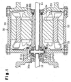
- Fig. 1 is a cross-sectional diagram of a differential apparatus 10 according to a preferred embodiment of the present invention.
- the differential apparatus 10 is mounted, for example, on a battery-operated forklift and transmits torque produced by a motor 50 to a left axle shaft 12 and a right axle shaft 14.
- the left axle shaft 12 and the right axle shaft 14 are connected to a left front wheel and a right front wheel of the forklift, respectively.
- the differential apparatus 10 absorbs the rotational difference produced between the left and right wheels when the forklift turns.
- the motor 50 is, for example, a three-phase induction motor that produces torque when energized.
- the motor 50 includes a stator, a rotor, and a cylindrical motor case 55.
- the stator produces a rotating magnetic field and includes a stator coil 51 and a stator core 52.
- the rotor through which secondary current is conducted, includes a rotor conductor 53 and a rotor core 54.
- the motor case 55 accommodates the stator and the rotor.
- Torque produced by the motor 50 is output by a cylindrical motor output shaft portion 56.
- the right axle shaft 14 rotatably extends through the motor output shaft portion 56.
- a side gear 16 is arranged on one end of each of the left axle shaft 12 and the right axle shaft 14.
- a pair of upper and lower differential pinions 18 meshes with the pair of side gears 16.
- the pinion shaft 20 extends through a gear case portion 22.
- the torque of the motor output shaft portion 56 is transmitted to the left axle shaft 12 and the right axle shaft 14 by the gear case portion 22.
- the differential apparatus 10 in the differential apparatus 10, the torque of the motor output shaft portion 56 is transmitted to the left axle shaft 12 and the right axle shaft 14 by the side gears 16, the differential pinions 18, and the pinion shaft 20 so as to cause the axle shafts 12 and 14 to rotate at a different speed but in the same direction as the motor output shaft portion 56.
- the differential apparatus 10 generates a rotational difference corresponding to a torque difference between the left and right wheels acting on the left axle shaft 12 and the right axle shaft 14.
- the motor output shaft portion 56 and the gear case portion 22 of the differential apparatus 10 are integrally cast with each other to form a single output shaft member. Such an integral structure eliminates the need for joining the motor output shaft 156 and the gear case 112 with the splines 114 and 116 as in the prior art example of Fig. 2. Further, the need for machining and connecting the joining portions of the motor output shaft 156 and the gear case 112 is eliminated. This reduces the manufacturing cost of the differential apparatus 10.
- the motor output shaft portion 56 and the gear case portion 22 are made of a material that may be cast, such as cast iron, and preferably, cast iron material having high ductility and high mechanical strength, such as ductile cast iron (FCD).
- the output shaft member having the motor output shaft portion 56 and the gear case portion 22 is supported in a smoothly rotatable manner by two bearings 30a and 30b.
- the bearing 30a is arranged adjacent to the gear case portion 22, and the bearing 30b is arranged on one end of the motor output shaft portion 56.
- the motor output shaft portion 56 and the gear case portion 22 are integrally cast with each other so that their axes are aligned with each other. Accordingly, the laborious process of aligning the rotation axes of the motor output shaft portion 56 and the gear case portion 22 with each other is not required when the output shaft member is attached to the bearings 30a and 30b. Further, the motor output shaft portion 56 and the gear case portion 22 remain coaxial even when the motor 50 generates high speed rotation. Thus, noise, vibrations, or frictional heat that would otherwise be caused by the motor output shaft portion 56, the gear case portion 22, and the bearings 30a and 30b are not produced.
- the rotation axis of the motor output shaft 156 and the rotation axis of the gear case 112 need to be precisely aligned with each other when the motor output shaft 156 and the gear case 112 are attached to two bearings. Without the precise alignment, the axes of the motor output shaft 156 and the gear case 112 may be misaligned from each other. This would produce noise, vibration, or frictional heat between the motor output shaft 156, the gear case 112 and the two bearings when the motor 150 generates high speed rotation.
- the differential apparatus 10 does not require the splines 114 and 116 to be formed. Thus, there is no spatial limitation in the axial direction of the motor in relation with dimension H in Fig. 2. This enables the size of the motor 50 to be increased compared with the prior art example of Fig. 2. As a result, a larger space may be provided for the stator coil 51 to increase the output of the motor 50.
- the present invention is not limited to such a structure.
- the motor output shaft portion 56 and the gear case portion 22 may be manufactured separately, and then integrally joined with each other through welding or the like with their rotation axes being aligned with each other. In other words, it is only required that a single integral member be used to function as the motor output shaft portion 56 and the gear case portion 22.
- the present invention is not limited to such a structure.
- the present invention is applicable to a case in which one or more transmission gears are provided between the motor 50 and the motor output shaft portion 56.
- the power source that produces torque for rotating the axle shafts may be a gasoline engine or a diesel engine instead of the motor 50.
- the present invention is applied to the differential apparatus 10, which is used for a front-wheel drive battery-operated forklift in the preferred embodiment, the present invention is not limited to such a structure.
- the present invention may be applied to a differential apparatus used in a rear-wheel drive vehicle, such as another type of an industrial vehicle or an automobile.
- the present invention relates to an improvement for a differential apparatus (10) that transmits torque produced by a motor (50) to two axle shafts (12, 14).
- a motor output shaft portion (56) is formed coaxially and integrally with a gear case (22).
Landscapes
- Engineering & Computer Science (AREA)
- Mechanical Engineering (AREA)
- Power Engineering (AREA)
- General Engineering & Computer Science (AREA)
- Chemical & Material Sciences (AREA)
- Combustion & Propulsion (AREA)
- Transportation (AREA)
- Retarders (AREA)
- Motor Power Transmission Devices (AREA)
- General Details Of Gearings (AREA)
Applications Claiming Priority (2)
| Application Number | Priority Date | Filing Date | Title |
|---|---|---|---|
| JP2003114410A JP2004316847A (ja) | 2003-04-18 | 2003-04-18 | ディファレンシャル装置 |
| JP2003114410 | 2003-04-18 |
Publications (2)
| Publication Number | Publication Date |
|---|---|
| EP1469232A2 true EP1469232A2 (fr) | 2004-10-20 |
| EP1469232A3 EP1469232A3 (fr) | 2010-04-07 |
Family
ID=32906094
Family Applications (1)
| Application Number | Title | Priority Date | Filing Date |
|---|---|---|---|
| EP04008982A Withdrawn EP1469232A3 (fr) | 2003-04-18 | 2004-04-15 | Differentiel |
Country Status (3)
| Country | Link |
|---|---|
| US (1) | US7220207B2 (fr) |
| EP (1) | EP1469232A3 (fr) |
| JP (1) | JP2004316847A (fr) |
Cited By (2)
| Publication number | Priority date | Publication date | Assignee | Title |
|---|---|---|---|---|
| EP3438502A1 (fr) * | 2011-02-24 | 2019-02-06 | Tai-Her Yang | Machine électrique double commande dotée d'un ensemble à engrenages d'épicycle contrôlable |
| DE102021004151A1 (de) | 2021-08-12 | 2023-02-16 | Mercedes-Benz Group AG | Antriebsvorrichtung zum elektrischen Antreiben eines Kraftwagens, insbesondere eines Personenkraftwagens |
Families Citing this family (9)
| Publication number | Priority date | Publication date | Assignee | Title |
|---|---|---|---|---|
| DE112010002682B4 (de) * | 2009-06-23 | 2023-01-12 | Karma Automotive LLC (n.d.Ges.d.Staates Delaware) | Antriebskonfiguration für ein Antriebssystem eines Hochgeschwindigkeitsmotors |
| CN102459957B (zh) | 2009-06-24 | 2015-05-06 | 菲斯科汽车科技集团有限公司 | 用于高混合动力串联/并联高速电机驱动系统的驱动配置 |
| JP2011046350A (ja) * | 2009-08-28 | 2011-03-10 | Showa Corp | モータ付デファレンシャル装置 |
| US8562470B2 (en) * | 2011-02-24 | 2013-10-22 | Tai-Her Yang | Dual-drive electric machine installed with epicycle gear type clutch |
| JP5617996B2 (ja) * | 2011-03-23 | 2014-11-05 | トヨタ自動車株式会社 | 車両用駆動装置 |
| JP5237424B2 (ja) * | 2011-09-27 | 2013-07-17 | 本田技研工業株式会社 | モータ式動力装置 |
| CN105291698A (zh) * | 2014-06-23 | 2016-02-03 | 杨皓捷 | 空心电机及空心电机电动车后桥 |
| CN106004424A (zh) * | 2016-07-20 | 2016-10-12 | 杭州傲拓迈科技有限公司 | 一种电动汽车同轴式减速机构驱动系统 |
| US12492742B2 (en) * | 2023-09-15 | 2025-12-09 | Borgwarner Inc. | Differentials with face gears for electrical drive systems |
Citations (4)
| Publication number | Priority date | Publication date | Assignee | Title |
|---|---|---|---|---|
| GB1209597A (en) | 1967-05-19 | 1970-10-21 | Internat Res And Dev Company L | Electric motor drive for a vehicle |
| JPH07156673A (ja) | 1993-12-01 | 1995-06-20 | Nissan Motor Co Ltd | 電気自動車用駆動装置 |
| EP0999083A2 (fr) | 1998-10-27 | 2000-05-10 | Röchling Getriebe KG | Axe d'entraínement avec moteur électrique incorporé |
| EP1274161A1 (fr) | 2001-07-04 | 2003-01-08 | The Electric Motor Company Limited | Moteur électrique avec un différentiel logé à l'intérieur du rotor du moteur |
Family Cites Families (13)
| Publication number | Priority date | Publication date | Assignee | Title |
|---|---|---|---|---|
| US2397357A (en) * | 1942-03-09 | 1946-03-26 | John J Kundig | Reaction turbine propeller |
| US4467230A (en) * | 1982-11-04 | 1984-08-21 | Rovinsky Robert S | Alternating current motor speed control |
| DE3675041D1 (de) * | 1985-03-19 | 1990-11-29 | Naotake Mohri | Differentialantrieb. |
| US5372213A (en) * | 1991-10-24 | 1994-12-13 | Aisin Aw Co., Ltd. | Oil circulating system for electric vehicle |
| US5396968A (en) * | 1992-03-18 | 1995-03-14 | Aisin Aw Co., Ltd. | Drive mechanism for electric car |
| JPH06098585A (en) * | 1992-09-14 | 1994-04-08 | Aisin Aw Co | Motor-driven vehicle |
| DE19524524A1 (de) * | 1995-07-05 | 1997-01-09 | Still Gmbh | Antriebsachse für ein Flurförderzeug |
| JPH0974713A (ja) * | 1995-09-04 | 1997-03-18 | Toyota Motor Corp | 電動モータ |
| JPH09229162A (ja) | 1996-02-26 | 1997-09-02 | Yanagawa Seiki Kk | デファレンシャル |
| US6402652B1 (en) * | 1999-10-15 | 2002-06-11 | New Venture Gear, Inc. | Continuously variable four-wheel drive transmission with traction control |
| JP2001132801A (ja) * | 1999-11-02 | 2001-05-18 | Mitsubishi Heavy Ind Ltd | 車両の動力伝達装置 |
| US6883235B2 (en) * | 2001-05-23 | 2005-04-26 | Meritor Heavy Vehicle Technology, Llc | Cast integral ring gear and differential case |
| US6940056B2 (en) * | 2003-10-09 | 2005-09-06 | Visteon Global Technologies, Inc. | Induction heat treatment method and coil and article treated thereby |
-
2003
- 2003-04-18 JP JP2003114410A patent/JP2004316847A/ja active Pending
-
2004
- 2004-04-15 EP EP04008982A patent/EP1469232A3/fr not_active Withdrawn
- 2004-04-15 US US10/826,041 patent/US7220207B2/en not_active Expired - Fee Related
Patent Citations (4)
| Publication number | Priority date | Publication date | Assignee | Title |
|---|---|---|---|---|
| GB1209597A (en) | 1967-05-19 | 1970-10-21 | Internat Res And Dev Company L | Electric motor drive for a vehicle |
| JPH07156673A (ja) | 1993-12-01 | 1995-06-20 | Nissan Motor Co Ltd | 電気自動車用駆動装置 |
| EP0999083A2 (fr) | 1998-10-27 | 2000-05-10 | Röchling Getriebe KG | Axe d'entraínement avec moteur électrique incorporé |
| EP1274161A1 (fr) | 2001-07-04 | 2003-01-08 | The Electric Motor Company Limited | Moteur électrique avec un différentiel logé à l'intérieur du rotor du moteur |
Cited By (3)
| Publication number | Priority date | Publication date | Assignee | Title |
|---|---|---|---|---|
| EP3438502A1 (fr) * | 2011-02-24 | 2019-02-06 | Tai-Her Yang | Machine électrique double commande dotée d'un ensemble à engrenages d'épicycle contrôlable |
| DE102021004151A1 (de) | 2021-08-12 | 2023-02-16 | Mercedes-Benz Group AG | Antriebsvorrichtung zum elektrischen Antreiben eines Kraftwagens, insbesondere eines Personenkraftwagens |
| WO2023016947A1 (fr) | 2021-08-12 | 2023-02-16 | Mercedes-Benz Group AG | Dispositif d'entraînement pour l'entrainement électrique d'un véhicule à moteur, plus particulièrement d'un véhicule à passagers |
Also Published As
| Publication number | Publication date |
|---|---|
| US20040209723A1 (en) | 2004-10-21 |
| US7220207B2 (en) | 2007-05-22 |
| EP1469232A3 (fr) | 2010-04-07 |
| JP2004316847A (ja) | 2004-11-11 |
Similar Documents
| Publication | Publication Date | Title |
|---|---|---|
| US6059684A (en) | Drive train for electric cars | |
| US7259493B2 (en) | Stator of two rotor single stator type electric motor | |
| US5396968A (en) | Drive mechanism for electric car | |
| CN102612614B (zh) | 具有行星齿轮组的电动机 | |
| US11293538B2 (en) | Vehicle drive device | |
| US6864607B2 (en) | Driving apparatus for vehicle | |
| US7717203B2 (en) | Wheel rotating apparatus and in-wheel motor vehicle | |
| US7220207B2 (en) | Differential apparatus | |
| JP2003191760A (ja) | 電動機付駆動装置 | |
| EP3783778A1 (fr) | Machine dynamo-électrique, et dispositif d'entraînement pour véhicule comprenant une machine dynamo-électrique | |
| US11015683B2 (en) | Vehicle driving device | |
| US20220161652A1 (en) | Front-and-rear-wheel-drive vehicle | |
| US11376952B1 (en) | In-wheel driving device and method for assembling the same | |
| EP3415353A1 (fr) | Voiture hybride et véhicule | |
| US11027616B2 (en) | Vehicle driving device | |
| US11241947B2 (en) | Vehicle driving device | |
| CN118355211A (zh) | 驱动装置 | |
| JP2008253004A (ja) | 車両用駆動装置 | |
| JP3693034B2 (ja) | 同軸回転電機 | |
| JP2016141198A (ja) | 車両の駆動装置 | |
| JP6365576B2 (ja) | ハイブリッド車及び車両 | |
| JP2017177965A (ja) | ハイブリッド車及び車両 | |
| JP2020167751A (ja) | 回転電機 | |
| JP2024039406A (ja) | 回転電機 | |
| WO2024202746A1 (fr) | Composant brasé et dispositif de conduite de véhicule |
Legal Events
| Date | Code | Title | Description |
|---|---|---|---|
| PUAI | Public reference made under article 153(3) epc to a published international application that has entered the european phase |
Free format text: ORIGINAL CODE: 0009012 |
|
| 17P | Request for examination filed |
Effective date: 20040415 |
|
| AK | Designated contracting states |
Kind code of ref document: A2 Designated state(s): AT BE BG CH CY CZ DE DK EE ES FI FR GB GR HU IE IT LI LU MC NL PL PT RO SE SI SK TR |
|
| AX | Request for extension of the european patent |
Extension state: AL HR LT LV MK |
|
| PUAL | Search report despatched |
Free format text: ORIGINAL CODE: 0009013 |
|
| AK | Designated contracting states |
Kind code of ref document: A3 Designated state(s): AT BE BG CH CY CZ DE DK EE ES FI FR GB GR HU IE IT LI LU MC NL PL PT RO SE SI SK TR |
|
| AX | Request for extension of the european patent |
Extension state: AL HR LT LV MK |
|
| 17Q | First examination report despatched |
Effective date: 20100408 |
|
| AKX | Designation fees paid |
Designated state(s): DE FR GB IT SE |
|
| STAA | Information on the status of an ep patent application or granted ep patent |
Free format text: STATUS: THE APPLICATION IS DEEMED TO BE WITHDRAWN |
|
| 18D | Application deemed to be withdrawn |
Effective date: 20111101 |