EP1469323A2 - Nebelvorhersagesystem - Google Patents
Nebelvorhersagesystem Download PDFInfo
- Publication number
- EP1469323A2 EP1469323A2 EP04101452A EP04101452A EP1469323A2 EP 1469323 A2 EP1469323 A2 EP 1469323A2 EP 04101452 A EP04101452 A EP 04101452A EP 04101452 A EP04101452 A EP 04101452A EP 1469323 A2 EP1469323 A2 EP 1469323A2
- Authority
- EP
- European Patent Office
- Prior art keywords
- control unit
- temperature
- change rate
- fog
- humidity
- Prior art date
- Legal status (The legal status is an assumption and is not a legal conclusion. Google has not performed a legal analysis and makes no representation as to the accuracy of the status listed.)
- Withdrawn
Links
- 238000012545 processing Methods 0.000 claims abstract description 11
- 239000003570 air Substances 0.000 claims description 30
- 238000012544 monitoring process Methods 0.000 claims description 8
- 230000009194 climbing Effects 0.000 claims description 5
- 230000005236 sound signal Effects 0.000 claims description 5
- 239000012080 ambient air Substances 0.000 claims description 2
- XLYOFNOQVPJJNP-UHFFFAOYSA-N water Substances O XLYOFNOQVPJJNP-UHFFFAOYSA-N 0.000 description 5
- 230000007423 decrease Effects 0.000 description 4
- 238000000034 method Methods 0.000 description 4
- 210000000707 wrist Anatomy 0.000 description 4
- 230000005540 biological transmission Effects 0.000 description 2
- 239000004973 liquid crystal related substance Substances 0.000 description 2
- 229920006395 saturated elastomer Polymers 0.000 description 2
- 230000002457 bidirectional effect Effects 0.000 description 1
- 230000036772 blood pressure Effects 0.000 description 1
- 239000003795 chemical substances by application Substances 0.000 description 1
- 230000000295 complement effect Effects 0.000 description 1
- 230000003247 decreasing effect Effects 0.000 description 1
- 230000001419 dependent effect Effects 0.000 description 1
- 238000010586 diagram Methods 0.000 description 1
- 230000000694 effects Effects 0.000 description 1
- 238000005259 measurement Methods 0.000 description 1
- 229910044991 metal oxide Inorganic materials 0.000 description 1
- 150000004706 metal oxides Chemical class 0.000 description 1
- 238000010295 mobile communication Methods 0.000 description 1
- 230000001681 protective effect Effects 0.000 description 1
- 239000004065 semiconductor Substances 0.000 description 1
Images
Classifications
-
- G—PHYSICS
- G04—HOROLOGY
- G04G—ELECTRONIC TIME-PIECES
- G04G21/00—Input or output devices integrated in time-pieces
- G04G21/02—Detectors of external physical values, e.g. temperature
-
- G—PHYSICS
- G01—MEASURING; TESTING
- G01W—METEOROLOGY
- G01W1/00—Meteorology
- G01W1/17—Catathermometers for measuring "cooling value" related either to weather conditions or to comfort of other human environment
Definitions
- the invention relates to a portable personal data processing device.
- a portable personal data processing device is, for example, a wrist-worn measuring device, a heart rate monitor, a subscriber terminal of a radio system, or a sports watch for use as an instrument in sports, hiking, sailing, mountain climbing and/or in snow sports.
- the object of the invention is to provide an improved portable personal data processing device.
- a portable personal data processing device comprising a control unit for controlling the device, a user interface coupled to the control unit for giving commands to the device and obtaining feedback on its operation, and a temperature sensor coupled to the control unit for measuring the ambient temperature.
- the device further comprises a humidity sensor coupled to the control unit for measuring the ambient humidity, and dependence information, which defines temperature values for the dew points corresponding to the humidity values, is stored in the device, and the control unit is configured to monitor the change rate of the measured temperature, to determine, on the basis of the change rate, the moment when the measured temperature reaches the temperature value of the dew point corresponding to the measured humidity on the basis of the dependence information, and to provide a forecast on fog appearance in relation to the moment employing the user interface.
- the device according to the invention provides several advantages. No portable personal data processing devices are known that could predict appearance of fog.
- the user receives information on fog appearance, and thus he can be prepare himself for it.
- the information on fog may have an effect on route selection or travel plans, for example.
- the device may help to avoid potential dangerous situations, such as falling or getting lost.
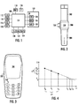
- the device comprises a control unit 100 for controlling the device, and a user interface 102 coupled to the control unit 100 for giving commands to the device and obtaining feedback on its operation.
- the device comprises an independent power source 110, for example a non-chargeable battery or a chargeable battery.
- a solar cell which generates energy from a light source and is either connected to the device or integrated into it, may also be utilized for obtaining power.
- Other prior art methods of generating power for a portable device may also be employed, such as a small-size generator, which produces power from movement and has been developed by watch producer Seiko@.
- the control unit 100 is usually implemented as a processor with software, but various hardware implementations are also feasible, such as a circuit consisting of logic components or one or more application-specific integrated circuits ASIC. A hybrid of these implementations is also possible. In selecting the implementation, a person skilled in the art will pay attention to the requirements set for the size and power consumption of the device, the required processing capacity and the production costs and volumes.
- the user interface 102 of the device typically comprises a display 104, a means 106 for producing sound and a keyboard 108.
- the display 104 may be a liquid crystal display, for example, but it can also be implemented by any appropriate prior art display technique.
- the means 106 for producing sound may be a loudspeaker or a simpler means for producing beeps or other sound signals.
- the keyboard 108 may even comprise a complete qwerty keyboard, a mere numeric keypad or only a few key buttons and/or rotary buttons.
- the user interface 102 may comprise other prior art user interface elements, for example various means for focusing a cursor (mouse, track ball, various arrow keys, etc.) or elements enabling audio control.
- the device further comprises two different sensors coupled to the control unit 100: a temperature sensor 120 for measuring the ambient temperature and a humidity sensor 122 for measuring the ambient humidity.
- a temperature sensor 120 for measuring the ambient temperature
- a humidity sensor 122 for measuring the ambient humidity.
- Such sensors are available from various producers. For example, Sensirion AG (whose web pages are found at the address www.sensirion.com) produces combined temperature and humidity sensors for this purpose which are implemented on one integrated CMOS circuit (complementary metal-oxide semiconductor circuit): the type of the surface mounting component is SHT1x and that of the component provided with a support SHT7x.
- CMOS circuit complementary metal-oxide semiconductor circuit
- Dependence information which defines the temperature values of dew points corresponding to the humidity values, is stored in the device.
- the dependence information can also be stored in the control unit 100 of the device.
- the information can be saved as tables or mathematical formulae, for instance.
- Air may contain only a certain maximum amount of water vapour, which is dependent on the air temperature. At a high temperature, air may contain more water vapour than at a low temperature. When air contains all the water it can retain, it is at a saturation point, i.e. its relative humidity is 100%. If the air temperature and humidity are measured, the dew point can be defined as the temperature to which the air temperature has to decrease so that air cannot retain all the water vapour. At the dew point, the humidity included in the air starts to condense into drops, i.e. a fog appears.
- An instrument called a psychometer is known to be used for determining the dew point. It comprises two standard thermometers in parallel: the bulb of one thermometer is in the air and the bulb of the other thermometer is in a wick wetted with water.
- the dew point can be calculated by the following formulae, for example.
- T dc -430,22+ 237,7*1n E -ln E +19,08 , where InE means the natural logarithm of number E.
- the control unit 100 is configured to monitor the rate of change of the measured temperature, to determine, on the basis of the rate of change, the moment when the measured temperature reaches the temperature value of the dew point corresponding to the measured humidity on the basis of the dependence information, and to provide a forecast on fog appearance in relation to the moment employing the user interface 102.
- the device of Figure 1 thus functions in such a manner that it measures the relative humidity of air by a humidity sensor 122 and the air temperature by a temperature sensor 120. After this, the device forms the dew point corresponding to the measured temperature and relative humidity. Then the device monitors the change rate of the air temperature employing the measurements carried out by the temperature sensor 120. Based on this change rate, the moment at which the air temperature reaches the dew point can be determined. Then a forecast can be provided on fog appearance in relation to this moment employing the user interface 102 of the device. Let us assume that in the example described above, where the starting temperature of air was 16.5 C and the dew point 4.3 C, the change rate of air temperature is 5 Celsius degrees per hour. In that case, the dew point is reached in 2.26 hours, i.e. in approximately two hours and sixteen minutes.
- Figure 4 illustrates the prediction of fog appearance: the horizontal axis describes the course of time and the vertical axis the decrease in temperature.
- the device measures the temperature To at moment to.
- the dew point T D is determined on the basis of this.
- the device monitors the change in temperature by measuring T 1 as the temperature at moment t 1 and T 2 as the temperature ad moment t 2 .
- T 1 the temperature at moment t 1
- T 2 the temperature ad moment t 2
- an estimate of how the temperature will drop can be formed.
- this first forecast is illustrated by a line where one point and one line alternate.
- the first forecast is linear as shown and the dew point T D is achieved at moment T F1 . According to the first forecast, fog will thus appear at moment T F1 .
- the control unit 100 is configured to show the amount of time left until the predicted fog appears in the user interface 102. This can be implemented for example by showing a decreasing counter on the display 104, the counter showing the time in hours and minutes within which fog will appear according to the forecast. The time when the fog will appear according to the forecast could also be shown on the display 104. In that case, the device could also include a clock 116, which would enable showing the actual time on the display 104.
- a separate clock circuit 116 is not necessarily needed, but when, for example, the control unit 100 is a processor with software, the clock can be implemented by forming the time by counting processor cycles by means of interruptions utilizing the software. If the device comprises a GPS receiver (Global Positioning System), the time information included in the GSP signal can be employed.
- GPS receiver Global Positioning System
- control unit 100 is configured to warn of approaching fog using a sound signal implemented by the user interface 102.
- the means 106 for producing sound is a loudspeaker, even clear words (either recorded words or words produced by a speech synthesizer) can be employed for warning of approaching fog.
- control unit 100 is configured to calculate the probability of fog appearance within a certain time based on a difference between the measured temperature and the temperature value of the dew point. In addition to the linear prediction described above, various heuristic rules, which will be described below, can be employed.
- the control unit 100 can be configured to present the probability of fog appearance as a percentage in the user interface 102. In an embodiment, the control unit 100 is configured to use one hour as the predetermined time. Thus, information according to which the probability of fog appearance within an hour is 90% can be shown on the display, for instance.
- control unit 100 is configured to take the time of the day into account in the monitoring of the temperature change rate. Temperature change rates in different seasons at certain places, e.g. at popular mountain climbing sites, can be stored in the control unit 100. In that case, the device should include calendar functions in addition to clock functions. According to a simple rule, the control unit 100 is configured to estimate that the direction of change in the temperature is descending and faster in the evening than in the day time: for example, in the afternoon the decrease rate of temperature may be 2 C/hour and in the evening 4 C/hour.
- the control unit 100 is configured to take the times of sunrise and sunset into account in monitoring the temperature change rate.
- the times of sunrise and sunset in certain areas may be stored in the control unit 100. If the device is provided with a GPS receiver, the control unit 100 may automatically retrieve the times of sunrise and sunset corresponding to the positioned location and the date retrieved from the calendar.
- the control unit 100 is configured to estimate that the temperature change rate is the highest at the sunrise and sunset.
- Figure 4 illustrates this second forecast improved on the basis of the sunset time by a line where two dots and one line alternate. The sun sets at moment t s , after which the air temperature decreases linearly as in the first forecast but steeper. According to the second forecast, fog appears at moment T F2 .
- the device further comprises an air pressure sensor 124 coupled to the control unit 100 for measuring the ambient air pressure, and the control unit 100 is configured to take account of the measured air pressure when monitoring the temperature change rate.
- the measured air pressure can be utilized by configuring the control unit 100 to estimate the cloudiness of the weather on the basis of the measured air pressure, for instance. According to a very rough rule, low air pressure would mean cloudy weather and high air pressure sunny weather.
- the control unit 100 is configured to estimate that the temperature change rate is lower in cloudy weather than in sunny weather.
- the control unit 100 is configured to estimate that the temperature change rate is slower when the sun sets in cloudy weather than when the sun sets in sunny weather.
- the device described in Figure 1 may be, for example, a wrist-worn measuring device shown in Figure 2.
- the electronics components shown in Figure 1, such as keys 108 and liquid crystal display 104 illustrated in Figure 2 are protected by a cover 200 (which is usually waterproof).
- the wrist-worn measuring device comprises a wristband 202, 204 for attaching the device to the wrist.
- the portable personal device may also be a sports watch intended to be used as an instrument in sports, hiking, sailing, mountain climbing and/or in snow sports.
- the sports watch may comprise an electronic compass 118 as shown in Figure 1.
- Sports watches are produced by Suunto®, for example (web pages at the address www.suunto.com).
- the device may also be a heart rate monitor for measuring the user's heart rate, and possibly other parameters that can be measured non-invasively (such as blood pressure).
- the device comprises a heart rate measuring unit 112 shown in Figure 1.
- a transmitter to be attached to the user's chest measures the user's ECG-accurate (electrocardiogram) heart rate and transmits the heart rate information telemetrically to the heart rate receiver attached to the user's wrist using magnetic coils in transmission.
- the heart rate monitor can also be implemented so that, instead of the solution consisting of a transmitter/receiver, the heart rate is measured directly from the wrist based on the pressure, for example.
- Other prior art methods for measuring the heart rate may also be employed, provided that they are suitable for use in a portable personal data processing device.
- Polar Electro® (web pages at the address www.polar.fi) designs and manufactures heart rate monitors which comprise an electrode transmitter belt worn around the chest and an actual heart rate monitor worn on the wrist.
- the electronics unit in the electrode transmitter belt receives heart rate information from electrodes, which are used for measuring one or more parameters of the heart rate information.
- the signal is transmitted to an ECG preamplifier, from which the signal is supplied to a transmitter via an AGC amplifier (Automatic Gain Control) and a power amplifier.
- the transmitter may be implemented as a coil, which transmits the heart rate information inductively to the receiver. For example, one burst of 5 kHz or a group of several bursts may correspond to one heartbeat.
- Information may be transmitted inductively or using another appropriate prior art data transmission method, for example over radio waves, optically or via a conduit.
- the receiver of the actual heart rate monitor can be implemented as a receiving coil, from which the received signal is transmitted via the signal receiver to the control unit 100, which controls and coordinates the function of the different components of the heart rate monitor.
- the heart rate monitor often comprises an interface 126 between the heart rate monitor and the outside world. Information stored in the heart rate monitor can be transmitted via the interface 126 to further processing, for example to a personal computer.
- the software of the heart rate monitor can also be updated via the interface 126.
- information required by some embodiments e.g. information on the sunrise and sunset times, can be loaded into the heart rate monitor via the interface 126.
- the device described in Figure 1 may also be a subscriber terminal of a radio system illustrated in Figure 3, for example a GSM (Global System for Mobile Communications) or a UMTS (Universal Mobile Telecommunications System) terminal.
- the electronics components/parts illustrated in Figure 1 are arranged inside a protective cover 300.
- the device comprises a radio transceiver 112 as shown in Figure 1 for implementing a bidirectional circuit-switched or packet-switched radio connection to a base station of the system. Using this radio connection, information required by some embodiments, for example sunrise and sunset times, can be loaded into the subscriber terminal.
- the control unit 100 of the device also includes a browser, the device user may retrieve required data from the web pages of the device producer using the radio connection, for instance.
Landscapes
- Environmental & Geological Engineering (AREA)
- Engineering & Computer Science (AREA)
- Life Sciences & Earth Sciences (AREA)
- Atmospheric Sciences (AREA)
- Biodiversity & Conservation Biology (AREA)
- Ecology (AREA)
- Environmental Sciences (AREA)
- Physics & Mathematics (AREA)
- General Physics & Mathematics (AREA)
- Electric Clocks (AREA)
Applications Claiming Priority (2)
| Application Number | Priority Date | Filing Date | Title |
|---|---|---|---|
| FI20030597A FI116098B (fi) | 2003-04-17 | 2003-04-17 | Kannettava henkilökohtainen tietojenkäsittelylaite |
| FI20030597 | 2003-04-17 |
Publications (3)
| Publication Number | Publication Date |
|---|---|
| EP1469323A2 true EP1469323A2 (de) | 2004-10-20 |
| EP1469323A9 EP1469323A9 (de) | 2005-01-19 |
| EP1469323A3 EP1469323A3 (de) | 2005-12-28 |
Family
ID=8565996
Family Applications (1)
| Application Number | Title | Priority Date | Filing Date |
|---|---|---|---|
| EP04101452A Withdrawn EP1469323A3 (de) | 2003-04-17 | 2004-04-08 | Nebelvorhersagesystem |
Country Status (3)
| Country | Link |
|---|---|
| US (1) | US7035736B2 (de) |
| EP (1) | EP1469323A3 (de) |
| FI (1) | FI116098B (de) |
Cited By (2)
| Publication number | Priority date | Publication date | Assignee | Title |
|---|---|---|---|---|
| EP2910938A1 (de) * | 2014-02-25 | 2015-08-26 | Sensirion AG | Tragbare elektronische Vorrichtung |
| US9671296B2 (en) | 2013-05-31 | 2017-06-06 | Sensirion Ag | Portable electronic device with integrated temperature sensor |
Families Citing this family (13)
| Publication number | Priority date | Publication date | Assignee | Title |
|---|---|---|---|---|
| JP5328159B2 (ja) | 2005-03-01 | 2013-10-30 | セルカコア・ラボラトリーズ・インコーポレーテッド | 多波長センサ発光体 |
| US20070117081A1 (en) * | 2005-10-31 | 2007-05-24 | Ford John H | System and Method for Delivering Information to Optimize Information Retention |
| WO2008112894A1 (en) * | 2007-03-15 | 2008-09-18 | Jiayi Li | Devices, systems, kits and methods for treatment of obesity |
| US20100004518A1 (en) | 2008-07-03 | 2010-01-07 | Masimo Laboratories, Inc. | Heat sink for noninvasive medical sensor |
| US8630691B2 (en) | 2008-08-04 | 2014-01-14 | Cercacor Laboratories, Inc. | Multi-stream sensor front ends for noninvasive measurement of blood constituents |
| US20100279822A1 (en) * | 2008-11-01 | 2010-11-04 | Ford John Hajime | Systems and methods for optimizing one or more audio tracks to a video stream |
| US9474953B1 (en) * | 2010-09-01 | 2016-10-25 | Jason Duke | System, method and processor-readable medium for wirelessly tracking basketball shots |
| US9687713B1 (en) | 2010-09-01 | 2017-06-27 | Jason Duke | System, method and processor-readable medium for wirelessly tracking basketball shots |
| US8845461B2 (en) * | 2010-09-01 | 2014-09-30 | Jason Duke | Hoop tracker |
| DE102018219370B3 (de) * | 2018-11-13 | 2019-10-24 | Robert Bosch Gmbh | Verfahren zur Erkennung eines Wassereintritts in einem Gehäuse, elektronische Schaltung zur Durchführung des Verfahrens, Gehäuse mit der elektronischen Schaltung und Fahrzeug mit dem Gehäuse |
| KR20220129033A (ko) | 2020-01-13 | 2022-09-22 | 마시모 코오퍼레이션 | 생리학적 파라미터 모니터링 기능이 있는 웨어러블 디바이스 |
| EP4370022A1 (de) | 2021-07-13 | 2024-05-22 | Masimo Corporation | Tragbare vorrichtung mit überwachung physiologischer parameter |
| US20250069490A1 (en) * | 2023-08-25 | 2025-02-27 | Saudi Arabian Oil Company | System and method for monitoring operational area |
Family Cites Families (11)
| Publication number | Priority date | Publication date | Assignee | Title |
|---|---|---|---|---|
| JPS607380A (ja) | 1983-06-28 | 1985-01-16 | Mitsubishi Heavy Ind Ltd | 海霧発生予測装置 |
| FI68734C (fi) | 1983-11-11 | 1985-10-10 | Seppo Saeynaejaekangas | Foerfarande och anordning foer telemetrisk maetning av hjaertslag och ekg-signal med anvaendande av ett magnetiskt naerfaelt |
| GB2190203A (en) | 1986-05-08 | 1987-11-11 | Protimeter Plc | Apparatus for use in diagnosing condensation or the likelihood thereof |
| GB9002685D0 (en) | 1990-02-07 | 1990-04-04 | Protimeter Plc | Fog warning device |
| EP0513420B1 (de) | 1991-05-17 | 1995-01-11 | Idt International Limited | Wettermelder |
| GB2261536B (en) | 1991-11-12 | 1995-03-15 | Norm Pacific Automat Corp | Automatic weather forecasting device |
| US6049069A (en) * | 1999-05-25 | 2000-04-11 | Valeo Electrical Systems, Inc. | Window fog detector |
| DE10021797A1 (de) | 2000-04-28 | 2001-10-31 | Norbert Scherer | Telefon, schnurloses Telefon oder tragbares Mobilhandtelefon |
| US6422062B1 (en) * | 2000-08-29 | 2002-07-23 | Delphi Technologies, Inc. | Integrated glass fog sensor unit |
| US6508408B2 (en) * | 2001-05-08 | 2003-01-21 | Delphi Technologies, Inc. | Automatic windglass fog prevention method for a vehicle climate control system |
| US6627851B2 (en) * | 2001-12-07 | 2003-09-30 | Delphi Technologies, Inc. | Power control method for a motor vehicle electric window heater |
-
2003
- 2003-04-17 FI FI20030597A patent/FI116098B/fi not_active IP Right Cessation
-
2004
- 2004-04-06 US US10/818,696 patent/US7035736B2/en not_active Expired - Lifetime
- 2004-04-08 EP EP04101452A patent/EP1469323A3/de not_active Withdrawn
Non-Patent Citations (1)
| Title |
|---|
| None * |
Cited By (3)
| Publication number | Priority date | Publication date | Assignee | Title |
|---|---|---|---|---|
| US9671296B2 (en) | 2013-05-31 | 2017-06-06 | Sensirion Ag | Portable electronic device with integrated temperature sensor |
| EP2910938A1 (de) * | 2014-02-25 | 2015-08-26 | Sensirion AG | Tragbare elektronische Vorrichtung |
| US9562869B2 (en) | 2014-02-25 | 2017-02-07 | Sensirion Ag | Portable electronic device |
Also Published As
| Publication number | Publication date |
|---|---|
| FI20030597L (fi) | 2004-10-18 |
| US20040220738A1 (en) | 2004-11-04 |
| US7035736B2 (en) | 2006-04-25 |
| EP1469323A3 (de) | 2005-12-28 |
| EP1469323A9 (de) | 2005-01-19 |
| FI116098B (fi) | 2005-09-15 |
| FI20030597A0 (fi) | 2003-04-17 |
Similar Documents
| Publication | Publication Date | Title |
|---|---|---|
| US7035736B2 (en) | Portable personal data processing device | |
| US12002341B2 (en) | Portable monitoring devices and methods of operating the same | |
| US11493637B2 (en) | Systems and methods for providing a health coaching message | |
| JP5505812B2 (ja) | 所要時間算出システム、所要時間算出プログラム及び所要時間算出方法 | |
| US20190240537A1 (en) | Exercise data display device, exercise data display method, and computer readable non-transitory storage medium with program stored thereon | |
| CN103919536A (zh) | 便携式生物计量监测装置及其操作方法 | |
| US20170273637A1 (en) | Information processing device and information processing method | |
| JP2023079989A (ja) | ランニングコース表示装置、及びプログラム | |
| JP5757982B2 (ja) | 活動支援装置、携帯端末、及び、活動支援システム | |
| JP2019125163A (ja) | 設定情報決定方法 | |
| JP2004038585A (ja) | 移動記録計 | |
| US12105208B2 (en) | Systems and methods for providing a health coaching message |
Legal Events
| Date | Code | Title | Description |
|---|---|---|---|
| PUAI | Public reference made under article 153(3) epc to a published international application that has entered the european phase |
Free format text: ORIGINAL CODE: 0009012 |
|
| AK | Designated contracting states |
Kind code of ref document: A2 Designated state(s): AT BE BG CH CY CZ DE DK EE ES FI FR GB GR HU IE IT LI LU MC NL PL PT RO SE SI SK TR |
|
| AX | Request for extension of the european patent |
Extension state: AL LT LV MK |
|
| PUAL | Search report despatched |
Free format text: ORIGINAL CODE: 0009013 |
|
| AK | Designated contracting states |
Kind code of ref document: A3 Designated state(s): AT BE BG CH CY CZ DE DK EE ES FI FR GB GR HU IE IT LI LU MC NL PL PT RO SE SI SK TR |
|
| AX | Request for extension of the european patent |
Extension state: AL LT LV MK |
|
| 17P | Request for examination filed |
Effective date: 20060213 |
|
| AKX | Designation fees paid |
Designated state(s): AT BE BG CH CY CZ DE DK EE ES FI FR GB GR HU IE IT LI LU MC NL PL PT RO SE SI SK TR |
|
| 17Q | First examination report despatched |
Effective date: 20070102 |
|
| STAA | Information on the status of an ep patent application or granted ep patent |
Free format text: STATUS: THE APPLICATION IS DEEMED TO BE WITHDRAWN |
|
| 18D | Application deemed to be withdrawn |
Effective date: 20081101 |