EP1469657A2 - Système d'appel téléphonique mains-libres - Google Patents
Système d'appel téléphonique mains-libres Download PDFInfo
- Publication number
- EP1469657A2 EP1469657A2 EP04008750A EP04008750A EP1469657A2 EP 1469657 A2 EP1469657 A2 EP 1469657A2 EP 04008750 A EP04008750 A EP 04008750A EP 04008750 A EP04008750 A EP 04008750A EP 1469657 A2 EP1469657 A2 EP 1469657A2
- Authority
- EP
- European Patent Office
- Prior art keywords
- call
- sound
- telephone line
- connection destination
- handset
- Prior art date
- Legal status (The legal status is an assumption and is not a legal conclusion. Google has not performed a legal analysis and makes no representation as to the accuracy of the status listed.)
- Granted
Links
Images


Classifications
-
- H—ELECTRICITY
- H04—ELECTRIC COMMUNICATION TECHNIQUE
- H04M—TELEPHONIC COMMUNICATION
- H04M1/00—Substation equipment, e.g. for use by subscribers
- H04M1/60—Substation equipment, e.g. for use by subscribers including speech amplifiers
- H04M1/6033—Substation equipment, e.g. for use by subscribers including speech amplifiers for providing handsfree use or a loudspeaker mode in telephone sets
-
- H—ELECTRICITY
- H04—ELECTRIC COMMUNICATION TECHNIQUE
- H04M—TELEPHONIC COMMUNICATION
- H04M1/00—Substation equipment, e.g. for use by subscribers
- H04M1/253—Telephone sets using digital voice transmission
- H04M1/2535—Telephone sets using digital voice transmission adapted for voice communication over an Internet Protocol [IP] network
Definitions
- the present invention relates to a call system for making a handsfree call using a microphone and a loudspeaker connected to an information terminal, and for making a handset call using a handset connected to the information terminal.
- IP Internet Protocol
- PSTN Public Switched Telephone Network
- SIP Session Initiation Protocol
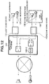
- a microphone see Fig. 1A
- a loudspeaker see Fig. 1B
- a handset is connected to the information terminal such as the personal computer by an interface such as a Universal Serial Bus (hereinafter, "USB"), and the information terminal and the handset thus connected can be used as a telephone set for handset call as a whole.
- USB Universal Serial Bus
- the handsfree call and the handset call cannot be freely changed over using the information terminal.
- an object of the present invention to provide a call system capable of freely changing over a handsfree call and a handset call using an information terminal.
- a call system comprising: a handsfree call microphone and a handsfree call loudspeaker; a first sound device that inputs and outputs a sound to the handsfree call microphone and the handsfree call loudspeaker, and that is included in an information terminal; a handset call microphone and a handset call loudspeaker; a second sound device that inputs and outputs the sound to the handset call microphone and the handset call loudspeaker; a handset connected to the information terminal; and selection means for selecting, as a connection destination on a transmitting end of a telephone line, at least one of the first sound device and the second device, and for selecting, as a connection destination on a receiving end the telephone line, at least one of the first sound device and the second sound device in accordance with a call state and an event, so as to set at least one of the handsfree call microphone and the handset call microphone as an input destination of the sound, and so as to set at least one of the handsfree call loudspeaker and the handset call loudspeak
- the handsfree loudspeaker may be set as the output destination of a ringer tone.
- the selection means may select the first sound device as the telephone line connection destination, and may change the call state to a handsfree call state.
- the selection means may select the second sound device as the telephone line connection destination, and may change the call state to a handset call state.
- the selection means may select neither the first nor second sound devices as the telephone line connection destination, and may change the call state to a waiting state.
- the selection means may select neither the first nor second sound devices as the telephone line connection destination, and may change the call state to a waiting state.
- the selection means may select the first sound device as the telephone line connection destination, and may change the call state to a handsfree call state.
- the selection means may select the second sound device as the telephone line connection destination, and may change the call state to a handset call state.
- the selection means may select the second sound device as the telephone line connection destination, and may change the call state to a handset call state.
- the selection means may select the first sound device as the telephone line connection destination, and may change the call state to a handsfree state.
- the selection means may select both the first sound device and the second sound device as the connection destination on the receiving end of the telephone line so as to set, as the output destination of the sound, both the handsfree call loudspeaker and the handset call loudspeaker.
- the selection means may select both the first sound device and the second sound device as the connection destination on the transmitting end of the telephone line so as to set, as the input destination of the sound, both the handsfree call microphone and the handset call microphone.
- the call system may further comprise: addition means for adding up the sound input from the handset call microphone through the second sound device and the sound input from the connection destination on the receiving end of the telephone line, and for outputting an addition value to the handsfree call loudspeaker through the first sound device.
- the call system may further comprise: recording means for recording a call; and addition means for adding up the sound input from the handset call microphone through the second sound device and the sound input from the connection destination on the receiving end of the telephone line, and for outputting an addition value to the recording means.
- the call system may further comprise: recording means for recording a call; and addition means for adding up the sound input from the handsfree call microphone through the first sound device and the sound input from the connection destination on the receiving end of the telephone line, and for outputting an addition value to the recording means.
- the call system may further comprise: gain control means for adjusting a level of the sound to be transmitted to the connection destination on the transmitting end of the telephone line.
- the call system may further comprise: gain control means for adjusting a level of the sound transmitted from the connection destination on the receiving end of the telephone line.
- the call system may further comprise: gain control means for adjusting a level of the sound transmitted from the connection destination on the receiving end of the telephone line, in accordance with the level of the sound to be transmitted to the connection destination on the transmitting end of the telephone line in a voiceless sound period.
- the call system may further comprise: semi-duplex communication means for permitting outputting the sound to be transmitted to the connection destination on the transmitting end of the telephone line and prohibiting outputting the sound transmitted from the connection destination on the receiving end of the telephone line when the sound to be transmitted is present at the connection destination on the transmitting end of the telephone line, and for prohibiting outputting a voiceless sound to the connection destination on the transmitting end of the telephone line and permitting outputting the sound transmitted from the connection destination on the receiving end of the telephone line when no sound to be transmitted is present at the connection destination on the transmitting end of the telephone line.
- the call system may further comprise: gain control means for increasing a gain of the sound to be transmitted to the connection destination on the transmitting end of the telephone line and reducing a gain of the sound transmitted from the connection destination on the receiving end of the telephone line when the sound to be transmitted is present at the connection destination on the transmitting end of the telephone line, and for reducing the gain of the sound to be transmitted to the connection destination on the transmitting end of the telephone line and increasing the gain of the sound transmitted from the connection destination on the receiving end of the telephone line when no sound to be transmitted is present at the connection destination on the transmitting end of the telephone line.
- the call system may further comprise: a plurality of the handsets; and connection means for connecting the plurality of handsets to different connection destinations, using a table that holds a correspondence between identification information on each of the plurality of handsets and the identification information on each of the different connection destinations.
- the present invention is characterized in that if an information terminal such as a personal computer or a Personal Digital Assistant (hereinafter, "PDA") is used for the IP telephone or the Internet telephone, one sound device that inputs and outputs a sound is automatically changed over to another sound device in accordance with a call state.
- PDA Personal Digital Assistant
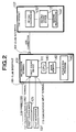
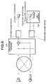
- an information terminal 101 is an information terminal such as a personal computer or a PDA, and includes a Central Processing Unit (hereinafter, "CPU") 141, a main memory 142 (e.g., a Dynamic Random Access Memory (hereinafter, "DRAM”)), and a first sound device 111 that inputs and outputs a sound.
- the first sound device 111 is a Peripheral Component Interconnect (hereinafter, "PCI") sound board or an onboard sound device, and includes a microphone input terminal 111-1 and a loudspeaker output terminal 111-2.
- a first microphone 131 is connected to the microphone input terminal 111-1.
- a first loudspeaker 121 is connected to the loudspeaker terminal 111-2.
- the first sound device 111 converts an analog sound input from the first microphone 131 into a digital sound and feeds the digitized sound to the CPU 141 or the like, and converts a digital sound input from the CPU 141 or the like into a digital sound and outputs the digital sound to the first loudspeaker 121.
- the information terminal 101 includes a Local Area Network (hereinafter, "LAN") interface 101-1 that connects the information terminal 101 to a LAN (not shown), and a USB interface 101-2 that connects the information terminal 101 to the USB.
- LAN Local Area Network
- An application program 143 for the IP telephone or the Internet telephone runs on the information terminal 101. Namely, the application program 143 stored in an external storage device or the like is temporarily stored in the main memory 142, read by the CPU 141, and executed.
- the LAN interface 101-1 is connected to the LAN, and the LAN is connected to the Internet through a router (not shown).
- the Internet is connected to the PSTN (not shown) through a gateway (not shown).
- another IP telephone set is connected to the Internet, and a conventional telephone set is connected to the PSTN.
- a USB handset 102 is connected to the information terminal 101 through the USB interface 101-2, and used by a user as a sound input and output device for the IP telephone or the Internet telephone.
- the USB handset 102 includes therein a second loudspeaker (receiver) 122, a second microphone (transmitter) 132, and a second sound device 112 for making calls.
- the second sound device 112 which is connected to the second microphone 132 and the second loudspeaker 122, converts an analog sound input from the second microphone 132 into a digital sound and feeds the digital sound to the USB, and converts a digital sound input from the USB into an analog sound and outputs the analog sound to the second loudspeaker 122.
- the application program 143 for the IP telephone or the Internet telephone that runs on the information terminal 101 can input and output a sound through the first sound device 111, the second sound device 112, a device driver, and the like.
- the application program 143 for the IP telephone or the Internet telephone that runs on the information terminal 101 holds information as to how a call state is, a waiting state, a handset call state, a handsfree call state, or the like in the main memory 142.
- the information terminal 101 is connected to a person on the other end of the line and changes the sound device for inputting and outputting the sound.
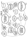
- Fig. 3 is a state transition view which illustrates a call state controlled by the application program 143 and the transition of the call state.
- call states include the waiting state S201, a call arrival state S202, the handsfree call state 203, the handset call state 204, a calling state S205 using the first sound device 111, and a calling state S206 using the second sound device 112.
- the application program 143 functions as selection means for selecting at least one of the first sound device 111 and the second sound device 112 as a telephone line connection destination so as to select at least one of the first microphone 131 and the second microphone 132 as a sound input destination and so as to select at least one of the first loudspeaker 121 and the second loudspeaker 122 as a sound output destination.
- the application program 143 makes selection as follows.
- the call state is changed to the call arrival state S202.
- the first sound device 111 produces a ringer tone from the first loudspeaker 121.
- a call button on the information terminal 101 is depressed while the call state is the call arrival state S202 (E252), then the telephone line connection destination is set at the first sound device and the call state is changed to the handsfree call state S203.
- the "depression of the call button on the information terminal 101" may be either the depression of a mechanical call button on the information terminal 101 or the depression of a visual call button displayed on a screen of the information terminal 101 by a keyboard or a mouse of the information terminal 101.
- USB handset 102 If the USB handset 102 is off hook while the call state is the call arrival state S202 (E253), then the telephone line connection destination is set at the second sound device 112 and the call state is changed to the handset call state S204.
- a disconnection button on the information terminal 101 is depressed while the call state is the handsfree call state S203 (E254), then no telephone line connection destination is set and the call state is changed to the waiting state S201.
- the "depression of the disconnection button on the information terminal 101" may be either the depression of a mechanical disconnection button on the information terminal 101 or the depression of a visual disconnection button displayed on the screen of the information terminal 101 by the keyboard or the mouse.
- USB handset 102 If the USB handset 102 is on hook while the call state is the handset call state S204 (E255), then no telephone line connection destination is set and the call state is changed to the waiting state S201.
- the call state is changed to the calling state S205 using the first sound device 111. If a telephone set of the person on the other end of the line is off hook after the call state is changed to the calling state S205 (E259), then the telephone line connection destination is set at the first sound device 111 and the call state is changed to the handsfree call state S203.
- USB handset 102 performs a calling operation while the call state is the waiting state S201 (E260), then the call state is changed to the calling state S206 using the second sound device 112. If the telephone set of the person on the other end of the line is off hook after the call state is changed to the calling state S206 (E261), then the telephone line connection destination is set at the second sound device 112 and the call state is changed to the handset call state S204.
- the telephone line connection destination is set at the second sound device 112 and the call state is changed to the handset call state S204.
- the telephone line connection destination is set at the first sound device 111 and the call state is changed to the handsfree call state S203.
- one sound device that inputs and outputs a sound is changed over to another sound device according to the call state. Therefore, differently from the conventional art, a disadvantage in that a ringer tone is inaudible since it is not output from the handset does not occur. In addition, the handset call and the handsfree call can be freely changed over on the application program 143.
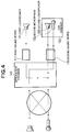
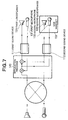
- the second embodiment is intended to improve a conventional disadvantage in that if a handset call is to be made, persons around the speaker or user cannot hear a sound of a person on the other end of the line, and to enable even those other than the user to hear the sound of the person on the other end of the line.
- the application program 143 distributes the sound of the person on the other end of the line that has been output only to the second sound device 112 so far, to both the first sound device 111 and the second sound device 112. By so distributing, the sound of the person on the other end of the line is output not only from the second loudspeaker 122 of the USB handset 102 but also from the first loudspeaker 121 for handsfree call.
- not only the sound input from the second sound device 112 but also the sound input from the first sound device 111 may be transmitted to the person on the other end of the line. If so, it is possible to transmit not only the sound input from the second microphone 132 of the USB handset 102 but also the sound input from the first microphone 131 for handsfree call to the person on the other end of the line. In this case, however, it is necessary to suppress each of an amplification gain of the sound to be output from the first loudspeaker 121 and an amplification gain of the sound input from the first microphone 131 to be a predetermined value or less so as to prevent a howl.
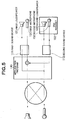
- the third embodiment is intended to improve a conventional disadvantage in that if a handset call is to be made, persons around the speaker or user cannot hear a conversation (dialogue), and to enable those other than the user to hear the conversation (dialogue).
- the application program 143 adds up the sound of the person on the other end of the line and the sound input from the second microphone 132, and outputs the added sound to the first sound device 111.
- the sound of the person on the other end of the line is output not only from the second loud speaker 122 of the USB handset 102 but also from the first loudspeaker 121 for handsfree call, and the sound input from the second microphone 132 of the USB handset 102 is output from the first loudspeaker 121 for handsfree call.
- not only the sound input from the second sound device 112 but also the sound input from the first sound device 111 may be transmitted to the person on the other end of the line.
- the sound input from the second microphone 132 of the USB handset 102 but also the sound input from the first microphone 131 for handsfree call can be transmitted to the person on the other end of the line.
- the application program 143 may add up the sound of the person on the other end of the line and the sound input from the second microphone 132 of the USB handset 102, and record the added sound in a recording section 151.
- the application program 143 may output the added sound either only to the recording section 151 or to both the recording section 151 and the first sound device 111.
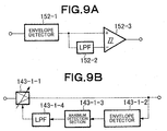
- a vocal sound/voiceless sound detection section 152 may be provided to detect whether there is a vocal sound or a voiceless sound.
- a control section 153 may be provided to stop a recording operation of the recording section 151 in the voiceless sound period, and to permit the recording operation only in a vocal sound period.
- the vocal sound/voiceless sound detection section 152 includes, for example, an envelope detector 152-1, a lowpass filter (hereinafter "LPF") 152-2, and a Schmidt trigger comparator 152-3.
- LPF lowpass filter
- the application program 143 may add up the sound of the person on the other end of the line and the sound input from the first microphone 131 for handsfree call, and record the added sound in the recording section 151.
- the fifth embodiment is intended to improve a conventional disadvantage in that if an absolute level of the sound input from the first microphone 131 for handsfree call or the second microphone 132 of the USB handset 102 is excessively high, a sound distortion occurs to the telephone set of the person on the other end of the line, and a conventional disadvantage in that if the absolute level is excessively low, the person on the other end of the line cannot hear the sound of the user even by setting a volume at a maximum on the side of the person on the other end of the line, and to enable automatically adjusting an input voice to a proper level.
- the application program 143 includes an automatic gain control (hereinafter "AGC") section 143-1.
- the AGC section 143-1 controls a gain of the sound input from the first microphone 131 for handsfree or that of the sound input from the second microphone 132 of the USB handset 102 so that a maximum of the absolute level of the sound input from the first microphone 131 for handsfree call or that input from the second microphone 132 of the USB handset 102 is constant.
- the AGC section 143-1 includes, for example, a variable gain amplifier 143-1-1, an envelope detector 143-1-2, a maximum detection section 143-1-3, and an LPF 143-1-4.
- the maximum detection section 143-1-3 may reduce a detected maximum with the passage of time.
- the sixth embodiment is intended to automatically adjust the correction of a volume of a received sound that has been conventionally made by the user himself or herself.
- the application program 143 includes an AGC section 143-2.
- the AGC 143-2 controls a gain of the volume of the sound transmitted from the person on the other end of the line so that the maximum of the absolute level of the sound transmitted from the person on the other end of the line is constant.
- the AGC section 143-2 includes, for example, the variable gain amplifier 143-1-1, the envelope detector 143-1-2, the maximum detection section 143-1-3, and the LPF 143-1-4.
- the maximum detection section 143-1-3 may reduce the detected maximum with the passage of time.
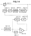
- the seventh embodiment is intended to correct the volume of the received sound (exercise gain control) based on a peripheral noise level, and to enable the user to always hear the sound with an audible volume.
- the application program 143 includes an AGC section 143-3.
- the AGC section 143-3 controls the gain of the volume of the sound transmitted from the person on the other end of the line so that a ratio of the maximum absolute level of the volume of the sound transmitted from the person on the other end of the line to the level of a peripheral noise collected by the first microphone 131 for handsfree call or the second microphone 132 of the USB handset 102 is a predetermined value.
- the AGC section 143-3 includes, for example, a variable gain amplifier 143-3-1, an envelope detector 143-3-2, a maximum detection section 143-3-3, an LPF 143-3-4, a divider 143-3-5, an envelope detector 143-3-6, an LPF 143-3-7, a Schmidt trigger comparator 143-3-8, a switch 143-3-9, and an LPF 143-3-10.
- the variable gain amplifier 143-3-1 is similar to the variable gain amplifier 143-1-1
- the envelope detector 143-3-2 is similar to the envelope detector 143-1-2.
- the maximum detection section 143-3-3 is similar to the maximum detection section 143-1-3
- the LPF 143-3-4 is similar to the LPF 141-1-4.
- the envelope detector 143-3-6 is similar to the envelope detector 152-1
- the LPF 143-3-7 is similar to the LPF 152-2
- the Schmidt trigger comparator 143-3-8 is similar to the Schmidt trigger comparator 152-3.
- the variable gain amplifier 143-3-1 amplifies an input sound signal transmitted from the person on the other end of the line by the gain so that a quotient output from the divider 143-3-5 is constant.
- the envelope detector 143-3-2 detects an envelope of an output of the variable gain amplifier 143-3-1.
- the maximum detection section 143-3-3 detects a maximum of an output of the envelope detector 143-3-2.
- the maximum detection section 143-3-3 may output the detected maximum while reducing it with the passage of time.
- the LPF 143-3-4 causes only low frequency components of an output of the maximum detection section 143-3-3 to pass.
- the divider 143-3-5 divides a level of an output of the LPF 143-3-4 by a level of an output of the LPF 143-3-10, and outputs the quotient to the variable gain amplifier 143-3-1.
- the envelope detector 143-3-6 detects an envelope of an input sound signal on the user's side.
- the LPF 143-3-7 causes only low frequency components of an output of the envelope detector 143-3-6 to pass.
- the Schmidt trigger comparator 143-3-8 compares a level of an output of the envelope detector 143-3-6 with that of the LPF 143-3-7, and outputs a comparison result.
- the Schmidt trigger comparator 143-3-8 has hysteresis characteristics.
- the switch 143-3-9 selects and outputs only the output of the envelope detector 143-3-6 in a voiceless sound period in accordance with an output of the Schmidt trigger comparator 143-3-8.
- the switch 143-3-0 holds a level of the output of the envelope detector 143-3-6 in a priority period just before a vocal sound period, in the vocal period.
- the LPF 143-3-10 causes only low frequency components of an output of the switch 143-3-9 to pass.
- the eighth embodiment is intended to make a semi-duplex communication handsfree call. If the user is to make a handsfree call, the first loudspeaker 121 and the first microphone 131 are used, positions of which are freely set. Therefore, if the first microphone 131 is disposed near the first loudspeaker 121, a howl often occurs.
- the eighth embodiment is intended to prevent the howl by holding a pseudo, semi-duplex communication while using full duplex lines.
- the application program 143 includes a vocal sound/voiceless sound detection section 143-4, and switches 143-5 and 143-6.
- the configuration of the vocal sound/voiceless sound detection section 143-4 is, for example, the same as that shown in Fig. 9A.
- the vocal sound/voiceless sound detection section 143-4 detects a vocal sound period and a voiceless sound period of a signal from the first microphone 131. In the vocal sound period, the vocal sound/voiceless sound detection section 143-4 turns on the switch 143-5 to transmit the sound from the first microphone 131 to the person on the other end of the line, and turns off the switch 143-6 so as not to output the sound of the person on the other end of the line to the first loudspeaker 121.
- the vocal sound/voiceless sound detection section 143-4 turns off the switch 143-5 so as not to transmit the sound from the first microphone 131 to the person on the other end of the line, and turns on the switch 143-6 to output the sound of the person on the other end of the line from the first loudspeaker 121.
- the ninth embodiment is equal to the eighth embodiment in that the both embodiments are intended to prevent the howl during a handsfree call but differs from the eighth embodiment in a method of realizing howl prevention.
- the application program 143 includes the vocal sound/voiceless sound detection section 143-4, and variable gain amplifiers 143-7 and 143-8.
- the configuration of the vocal sound/voiceless sound detection section 143-4 is, for example, the same as that shown in Fig. 9A.
- the vocal sound/voiceless sound detection section 143-4 detects the vocal sound period and the voiceless sound period of the signal from the first microphone 131. In the vocal sound period, the vocal sound/voiceless sound detection section 143-4 increases a gain of the variable gain amplifier 143-7 and reduces a gain of the variable gain amplifier 143-8. In the voiceless sound period, the vocal sound/voiceless sound detection section 143-4 reduces the gain of the variable gain amplifier 143-7 and increases the gain of the variable gain amplifier 143-8.
- the ninth embodiment differently from the eighth embodiment, even if the sound of the user is in the vocal sound period, the sound of the person on the other end of the line is audible.
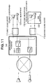
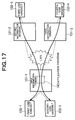
- the tenth embodiment is intended to connect a plurality of USB handsets to one information terminal, and to enable the respective USB handsets to make calls to different persons.
- Fig. 17 illustrates the form of connection according to the tenth embodiment.
- two USB handsets (a first USB handset 102-1 and a second USB handset 102-2), for example, are connected to a first information terminal 101-1.
- the first and second USB handsets 102-1 and 102-2 are connected to the application program 143.
- one USB handset (a third USB handset 102-3) is connected to a second information terminal 101-2, and one USB handset (a fourth USB handset 102-4) is connected to a third information terminal 101-3.
- the party on the other end of the line for the first USB handset 102-1 is the third USB handset 102-3, and that for the second USB handset 102-2 is the fourth USB handset 102-4.
- the first information terminal 101-1 discriminates the first USB handset 102-1 and the second USB handset 102-2 from each other by checking USB device numbers and channels allocated to the respective USB handsets 102-1 and 102-2.
- the first information terminal 101-1 discriminates the third USB handset 102-3 and the fourth USB handset 102-4 by checking pairs of IP addresses and Real-Time Transport Protocols (hereinafter, "RTP") allocated to the respective handsets 102-3 and 102-4.
- RTP Real-Time Transport Protocol
- the application program 143 holds an intra-application channel management table shown below.
- Each record of the intra-application channel management table includes such fields as a channel field, a USB device field, a counterpart IP address field, and an RTP port number field. One record is provided for each communication direction of each call.
- the intra-application channel management table is set as shown below.
- Intra-application channel management table of first information terminal Channel USB device Counterpart IP address RTP port number Channel 1 transmission USB device 1 Channel 1 reception USB device 1 Channel 2 transmission USB device 2 Channel 2 reception USB device 2
- Intra-application channel management table of first information terminal Channel USB device Counterpart IP address RTP port number Channel 1 transmission USB device 1 IP address of third information terminal Channel 1 reception USB device 1 IP address of third information terminal Channel 2 transmission USB device 2 Channel 2 reception USB device 2
- the intra-application channel management table is set as shown below.
- Intra-application channel management table of first information terminal Channel USB device Counterpart IP address RTP port number Channel 1 transmission USB device 1 IP address of third information terminal A Channel 1 reception USB device 1 IP address of third information terminal B Channel 2 transmission USB device 2 Channel 2 reception USB device 2
- the voice of the person on the other end of the line can be output from the handsfree call loudspeaker while a handset call is being made. Therefore, persons other than the user who is making the handset call can hear the sound of the person on the other end of the line.
- the sound input from the handsfree call microphone and the sound input from the microphone of the handset can be transmitted to the person on the other end of the line. Therefore, sounds of a plurality of people on the user's side can be transmitted to the person on the other end of the line.
- the voice of the person on the other end of the line and the voice picked up by the microphone of the hand set can be output from the handsfree call loudspeaker while a handset call is being made. Therefore, those other than the persons who are holding a telephone conversation can hear the sounds of the user and the person on the other end of the line.
- the sound of the person on the other end of the line and the sound input from the microphone of the handset can be recorded while a handset call is being made.
- the sound of the person on the other end of the line and the sound input from the handsfree call microphone can be recorded while a handsfree call is being made.
- the level of the sound to be transmitted to the connection destination on the transmitting end of the telephone line is adjusted. Therefore, the person on the other end of the line can hear the sound with an appropriate sound volume.
- the level of the sound transmitted from the connection destination on the receiving end of the telephone line is adjusted. Therefore, the user can hear the sound of the person on the other end of the line with an appropriate sound volume.
- the level of the sound transmitted from the connection destination on the receiving end of the telephone line is adjusted in accordance with the sound to be transmitted to the connection destination on the transmitting end of the telephone line in the voiceless sound period. Therefore, even if there is a background noise on the user's side, the user can hear the sound of the person on the other end of the line with an appropriate sound volume in accordance with a level of the background noise.
- the output of the sound to be transmitted to the connection destination on the transmitting end of the telephone line is permitted, and the output of the sound transmitted from the connection destination on the receiving end of the telephone line is prohibited when the sound to be transmitted is present at the connection destination on the transmitting end of the telephone line.
- the output of a voiceless sound to the connection destination on the transmitting end of the telephone line is prohibited, and the output of the sound transmitted from the connection destination on the receiving end of the telephone line is permitted when no sound to be transmitted is present at the connection destination on the transmitting end of the telephone line. Therefore, it is possible to prevent a howl.
- the gain of the sound to be transmitted to the connection destination on the transmitting end of the telephone line is increased, and the gain of the sound transmitted from the connection destination on the receiving end of the telephone line is reduced when the sound to be transmitted is present at the connection destination on the transmitting end of the telephone line.
- the gain of the sound to be transmitted to the connection destination on the transmitting end of the telephone line is reduced, and the gain of the sound transmitted from the connection destination on the receiving end of the telephone line is increased when no sound to be transmitted is present at the connection destination on the transmitting end of the telephone line. Therefore, it is possible to prevent a howl.
- the call system includes a plurality of the handsets, and the handsets are connected to different connection destinations using a table that holds a correspondence between identification information on each of the handsets and the identification information on each of the connection destinations. Therefore, it is possible to realize a plurality of calls using single information equipment.
Landscapes
- Engineering & Computer Science (AREA)
- Signal Processing (AREA)
- Telephone Function (AREA)
- Mobile Radio Communication Systems (AREA)
Applications Claiming Priority (2)
| Application Number | Priority Date | Filing Date | Title |
|---|---|---|---|
| JP2003111715 | 2003-04-16 | ||
| JP2003111715A JP4167533B2 (ja) | 2003-04-16 | 2003-04-16 | 通話システム |
Publications (3)
| Publication Number | Publication Date |
|---|---|
| EP1469657A2 true EP1469657A2 (fr) | 2004-10-20 |
| EP1469657A3 EP1469657A3 (fr) | 2010-07-21 |
| EP1469657B1 EP1469657B1 (fr) | 2015-02-18 |
Family
ID=32906041
Family Applications (1)
| Application Number | Title | Priority Date | Filing Date |
|---|---|---|---|
| EP04008750.4A Expired - Lifetime EP1469657B1 (fr) | 2003-04-16 | 2004-04-13 | Système d'appel téléphonique mains-libres |
Country Status (5)
| Country | Link |
|---|---|
| US (1) | US7206406B2 (fr) |
| EP (1) | EP1469657B1 (fr) |
| JP (1) | JP4167533B2 (fr) |
| AU (1) | AU2004201582B2 (fr) |
| CA (1) | CA2464076C (fr) |
Cited By (1)
| Publication number | Priority date | Publication date | Assignee | Title |
|---|---|---|---|---|
| EP2031843A3 (fr) * | 2007-08-30 | 2016-04-20 | Brother Kogyo Kabushiki Kaisha | Terminal de téléphonie IP, procédé de commande de celui-ci et support de stockage lisible sur ordinateur |
Families Citing this family (11)
| Publication number | Priority date | Publication date | Assignee | Title |
|---|---|---|---|---|
| US7280852B2 (en) * | 2002-09-30 | 2007-10-09 | Matsushita Electric Industrial Co., Ltd. | In-vehicle hands-free apparatus |
| USD525241S1 (en) * | 2003-11-17 | 2006-07-18 | Jabra Corporation | Portable speakerphone with a pivoting microphone boom |
| US8254898B2 (en) * | 2005-02-04 | 2012-08-28 | Avaya Inc. | Message handling based on the state of a telecommunications terminal |
| JP4688701B2 (ja) * | 2006-03-09 | 2011-05-25 | 富士通東芝モバイルコミュニケーションズ株式会社 | 通信端末 |
| JP4730964B2 (ja) * | 2006-09-15 | 2011-07-20 | 株式会社ナカヨ通信機 | 簡易電話会議装置 |
| JP2008092269A (ja) * | 2006-10-02 | 2008-04-17 | Matsushita Electric Ind Co Ltd | ハンズフリー通話装置 |
| JP4858479B2 (ja) * | 2007-08-30 | 2012-01-18 | ブラザー工業株式会社 | Ip電話端末、プログラム |
| JP2011124775A (ja) * | 2009-12-10 | 2011-06-23 | Hitachi Ltd | 通信システム |
| JP6155555B2 (ja) * | 2012-05-30 | 2017-07-05 | 日本電気株式会社 | 情報処理システム、情報処理方法、情報処理装置、携帯端末およびその制御方法と制御プログラム |
| US9104384B2 (en) * | 2013-05-13 | 2015-08-11 | International Microsystems, Inc. | Portable USB mass storage device |
| US10861463B2 (en) * | 2018-01-09 | 2020-12-08 | Sennheiser Electronic Gmbh & Co. Kg | Method for speech processing and speech processing device |
Family Cites Families (24)
| Publication number | Priority date | Publication date | Assignee | Title |
|---|---|---|---|---|
| CA1233925A (fr) * | 1985-05-10 | 1988-03-08 | Gordon J. Reesor | Telephone numerique a haut-parleur |
| US4790002A (en) * | 1986-08-08 | 1988-12-06 | Dictaphone Corporation | Telephone device and method for operating a telephone device |
| TW226510B (en) * | 1993-01-19 | 1994-07-11 | Novatel Comm Ltd | Wireline interface for cellular telephone |
| US5557653A (en) * | 1993-07-27 | 1996-09-17 | Spectralink Corporation | Headset for hands-free wireless telephone |
| US6081724A (en) * | 1996-01-31 | 2000-06-27 | Qualcomm Incorporated | Portable communication device and accessory system |
| JPH09224081A (ja) | 1996-02-15 | 1997-08-26 | Matsushita Graphic Commun Syst Inc | 家庭用情報通信装置 |
| JPH09289474A (ja) * | 1996-04-23 | 1997-11-04 | Saitama Nippon Denki Kk | ハンズフリー通話装置 |
| US5978689A (en) * | 1997-07-09 | 1999-11-02 | Tuoriniemi; Veijo M. | Personal portable communication and audio system |
| JPH11163762A (ja) * | 1997-11-28 | 1999-06-18 | Toshiba Corp | ハンズフリーユニット |
| DE19808254A1 (de) | 1998-02-27 | 1999-09-02 | Aventis Res & Tech Gmbh & Co | Chemische Verbindung |
| US5991398A (en) * | 1998-04-17 | 1999-11-23 | Ameritech Corporation | Telephone terminal apparatus and method |
| TW391592U (en) * | 1998-12-14 | 2000-05-21 | Inventec Corp | New telephone device |
| SE525728C2 (sv) | 1999-01-27 | 2005-04-12 | Ericsson Telefon Ab L M | Portabel telekommunikationsanordning för flera ljudtillbehör |
| US6792295B1 (en) * | 2000-01-12 | 2004-09-14 | General Motors Corporation | Wireless device for use with a vehicle embedded phone |
| EP1154621B1 (fr) * | 2000-05-11 | 2008-01-23 | Lucent Technologies Inc. | Terminal mobile pour système de télécommunication |
| US6731751B1 (en) * | 2000-06-27 | 2004-05-04 | Vxi Corporation | Apparatus for cordless computer telephony |
| JP3949886B2 (ja) | 2000-09-20 | 2007-07-25 | 株式会社東芝 | 携帯型オーディオ再生装置及び携帯型オーディオ再生装置の出力先制御方法 |
| US7340041B2 (en) * | 2000-11-17 | 2008-03-04 | Sanyo Electric Co., Ltd. | Telephone device having operation function by voice input |
| DE10120525A1 (de) * | 2001-04-26 | 2002-11-07 | Harman Audio Electronic Sys | Schaltungsanordnung zur Audiowiedergabe und zum Freisprechen in einem Kraftfahrzeug |
| JP2002345042A (ja) | 2001-05-22 | 2002-11-29 | Matsushita Electric Ind Co Ltd | 携帯情報端末及び携帯情報端末の出力制御方法 |
| JP2002368852A (ja) | 2001-06-08 | 2002-12-20 | Susumu Noguchi | インターネット接続サービス対応の専用電話機 |
| DE20200819U1 (de) * | 2001-09-10 | 2002-05-29 | Lee, Ching-Chuan, Taipeh/T'ai-pei | Freisprechvorrichtung für ein schnurloses Telefon |
| US6937854B2 (en) * | 2002-01-04 | 2005-08-30 | Vtech Telecommunications, Limited | Apparatus for conducting a conference call between a wireless line and a land line using customer premise equipment |
| US6792296B1 (en) * | 2002-10-01 | 2004-09-14 | Motorola, Inc. | Portable wireless communication device and methods of configuring same when connected to a vehicle |
-
2003
- 2003-04-16 JP JP2003111715A patent/JP4167533B2/ja not_active Expired - Lifetime
-
2004
- 2004-04-13 EP EP04008750.4A patent/EP1469657B1/fr not_active Expired - Lifetime
- 2004-04-13 CA CA002464076A patent/CA2464076C/fr not_active Expired - Lifetime
- 2004-04-14 US US10/823,739 patent/US7206406B2/en not_active Expired - Lifetime
- 2004-04-15 AU AU2004201582A patent/AU2004201582B2/en not_active Expired
Cited By (1)
| Publication number | Priority date | Publication date | Assignee | Title |
|---|---|---|---|---|
| EP2031843A3 (fr) * | 2007-08-30 | 2016-04-20 | Brother Kogyo Kabushiki Kaisha | Terminal de téléphonie IP, procédé de commande de celui-ci et support de stockage lisible sur ordinateur |
Also Published As
| Publication number | Publication date |
|---|---|
| US7206406B2 (en) | 2007-04-17 |
| JP4167533B2 (ja) | 2008-10-15 |
| CA2464076A1 (fr) | 2004-10-16 |
| EP1469657A3 (fr) | 2010-07-21 |
| US20040209656A1 (en) | 2004-10-21 |
| EP1469657B1 (fr) | 2015-02-18 |
| AU2004201582A1 (en) | 2004-11-04 |
| CA2464076C (fr) | 2008-04-08 |
| AU2004201582B2 (en) | 2008-11-06 |
| JP2004320457A (ja) | 2004-11-11 |
Similar Documents
| Publication | Publication Date | Title |
|---|---|---|
| US8868052B2 (en) | System and method for wireless conferencing | |
| CA2464076C (fr) | Systeme d'appel | |
| EP1336253B1 (fr) | Dispositif portable de communication | |
| JPH09261134A (ja) | 電話送受器インタフェース装置 | |
| US8483409B2 (en) | Volume adjustment for multiple voice over internet protocal streams | |
| KR101135382B1 (ko) | 통신기기의 음성신호 제어장치 및 그 제어방법 | |
| US6934383B2 (en) | Apparatus for reducing echoes and noises in telephone | |
| JP5040511B2 (ja) | 話者別受話音量調整機能を有する電話装置 | |
| US6101253A (en) | Ultra-slim telephone set | |
| JP2006270601A (ja) | ハンズフリー通話装置 | |
| US6845242B1 (en) | Cordless telephone system | |
| EP2056576A1 (fr) | Son amélioré dans une session de communication en conférence | |
| CN101379809B (zh) | 通信会议系统、语音变换装置以及信号转换适配器 | |
| KR100810371B1 (ko) | 휴대단말기 복합 충전 장치 | |
| JP2001094604A (ja) | マルチメディア情報通信システム及びコンピュータ装置 | |
| JP3047253B2 (ja) | 電話端末装置 | |
| US20080043994A1 (en) | Telephone having public-address system | |
| KR200254448Y1 (ko) | 전화기 음량 조절 장치 | |
| JPH10500813A (ja) | 電話切換えインターフェース | |
| JPS61212151A (ja) | ハンズフリ−機能付電話機 | |
| KR20080086800A (ko) | 개인용다자간통화기 | |
| JP2007318614A (ja) | 端末装置 | |
| JPH11220554A (ja) | 通話録音用アダプタ | |
| JPH0546141U (ja) | コードレス電話装置 | |
| AU2007203414A1 (en) | Telephone transmission distortion prevention method and apparatus |
Legal Events
| Date | Code | Title | Description |
|---|---|---|---|
| PUAI | Public reference made under article 153(3) epc to a published international application that has entered the european phase |
Free format text: ORIGINAL CODE: 0009012 |
|
| AK | Designated contracting states |
Kind code of ref document: A2 Designated state(s): AT BE BG CH CY CZ DE DK EE ES FI FR GB GR HU IE IT LI LU MC NL PL PT RO SE SI SK TR |
|
| AX | Request for extension of the european patent |
Extension state: AL HR LT LV MK |
|
| PUAL | Search report despatched |
Free format text: ORIGINAL CODE: 0009013 |
|
| AK | Designated contracting states |
Kind code of ref document: A3 Designated state(s): AT BE BG CH CY CZ DE DK EE ES FI FR GB GR HU IE IT LI LU MC NL PL PT RO SE SI SK TR |
|
| AX | Request for extension of the european patent |
Extension state: AL HR LT LV MK |
|
| 17P | Request for examination filed |
Effective date: 20100702 |
|
| 17Q | First examination report despatched |
Effective date: 20100831 |
|
| AKX | Designation fees paid |
Designated state(s): DE GB |
|
| GRAP | Despatch of communication of intention to grant a patent |
Free format text: ORIGINAL CODE: EPIDOSNIGR1 |
|
| INTG | Intention to grant announced |
Effective date: 20140919 |
|
| GRAS | Grant fee paid |
Free format text: ORIGINAL CODE: EPIDOSNIGR3 |
|
| GRAA | (expected) grant |
Free format text: ORIGINAL CODE: 0009210 |
|
| RIN1 | Information on inventor provided before grant (corrected) |
Inventor name: KITAMI, HIDEO Inventor name: KOBAYASHI, YOSHIKAZU |
|
| AK | Designated contracting states |
Kind code of ref document: B1 Designated state(s): DE GB |
|
| REG | Reference to a national code |
Ref country code: GB Ref legal event code: FG4D |
|
| REG | Reference to a national code |
Ref country code: DE Ref legal event code: R096 Ref document number: 602004046619 Country of ref document: DE Effective date: 20150326 |
|
| RAP2 | Party data changed (patent owner data changed or rights of a patent transferred) |
Owner name: NEC PLATFORMS, LTD. |
|
| REG | Reference to a national code |
Ref country code: DE Ref legal event code: R097 Ref document number: 602004046619 Country of ref document: DE |
|
| PLBE | No opposition filed within time limit |
Free format text: ORIGINAL CODE: 0009261 |
|
| STAA | Information on the status of an ep patent application or granted ep patent |
Free format text: STATUS: NO OPPOSITION FILED WITHIN TIME LIMIT |
|
| 26N | No opposition filed |
Effective date: 20151119 |
|
| PGFP | Annual fee paid to national office [announced via postgrant information from national office to epo] |
Ref country code: DE Payment date: 20230420 Year of fee payment: 20 |
|
| PGFP | Annual fee paid to national office [announced via postgrant information from national office to epo] |
Ref country code: GB Payment date: 20230419 Year of fee payment: 20 |
|
| REG | Reference to a national code |
Ref country code: DE Ref legal event code: R071 Ref document number: 602004046619 Country of ref document: DE |
|
| REG | Reference to a national code |
Ref country code: GB Ref legal event code: PE20 Expiry date: 20240412 |
|
| PG25 | Lapsed in a contracting state [announced via postgrant information from national office to epo] |
Ref country code: GB Free format text: LAPSE BECAUSE OF EXPIRATION OF PROTECTION Effective date: 20240412 |
|
| PG25 | Lapsed in a contracting state [announced via postgrant information from national office to epo] |
Ref country code: GB Free format text: LAPSE BECAUSE OF EXPIRATION OF PROTECTION Effective date: 20240412 |