EP1469703B1 - Method of processing an acoustical signal and a hearing instrument - Google Patents
Method of processing an acoustical signal and a hearing instrument Download PDFInfo
- Publication number
- EP1469703B1 EP1469703B1 EP20040405272 EP04405272A EP1469703B1 EP 1469703 B1 EP1469703 B1 EP 1469703B1 EP 20040405272 EP20040405272 EP 20040405272 EP 04405272 A EP04405272 A EP 04405272A EP 1469703 B1 EP1469703 B1 EP 1469703B1
- Authority
- EP
- European Patent Office
- Prior art keywords
- gain
- input signal
- signal
- room impulse
- value
- Prior art date
- Legal status (The legal status is an assumption and is not a legal conclusion. Google has not performed a legal analysis and makes no representation as to the accuracy of the status listed.)
- Expired - Lifetime
Links
Images


Classifications
-
- H—ELECTRICITY
- H04—ELECTRIC COMMUNICATION TECHNIQUE
- H04R—LOUDSPEAKERS, MICROPHONES, GRAMOPHONE PICK-UPS OR LIKE ACOUSTIC ELECTROMECHANICAL TRANSDUCERS; ELECTRIC HEARING AIDS; PUBLIC ADDRESS SYSTEMS
- H04R25/00—Electric hearing aids
- H04R25/50—Customised settings for obtaining desired overall acoustical characteristics
- H04R25/505—Customised settings for obtaining desired overall acoustical characteristics using digital signal processing
-
- H—ELECTRICITY
- H04—ELECTRIC COMMUNICATION TECHNIQUE
- H04R—LOUDSPEAKERS, MICROPHONES, GRAMOPHONE PICK-UPS OR LIKE ACOUSTIC ELECTROMECHANICAL TRANSDUCERS; ELECTRIC HEARING AIDS; PUBLIC ADDRESS SYSTEMS
- H04R2225/00—Details of deaf aids covered by H04R25/00, not provided for in any of its subgroups
- H04R2225/43—Signal processing in hearing aids to enhance the speech intelligibility
Definitions
- This invention is in the field of processing signals in or for hearing instruments. It more particularly relates to a method of converting an acoustic input signal into an output signal, a. hearing instrument, and to a method of manufacturing a hearing instrument.
- Reverberation is a major problem for hearing impaired persons.
- the reason is that, in addition to the missing spectral cues for speech intelligibility from the broadening of the auditory filters (i.e. the reduced spectral discrimination ability of the impaired ear, due to defect outer hair cells, resulting in less sharply tuned auditory filters in the impaired ear), the temporal cues also are mitigated by the reverberation. Onsets, speech pauses etc. are no longer perceivable. Thus, severe intelligibility reductions as well as comfort decreases occur.
- reverberation is a filtering (convolution) of the clean signal, for example a speech signal, with the room impulse response (RIR) from the speaker to the hearing impaired person.
- RIR room impulse response
- These room impulse responses tend to be very long, in the order of several hundred milliseconds up to several seconds for large cathedrals or main train stations. The long RIR thus slurs the speech pauses.
- 'de-convolution' i.e. the estimation and inversion of the RIR, with which the reverberated signal arriving at the Hearing Instrument (HI) can get filtered and thus perfectly restored to the original clean or 'dry' signal.
- deconvolution or inversion of a filter response is a well known process.
- the problems lie in the following points:
- P xx (t,f) is the power spectral density of a signal x(n).
- T is an (arbitrary) delay.
- the reverberation power at any time t is equal to the signal power of the speaker at an earlier time t-T, and attenuated by the exponential term e -2 ⁇ T .
- the reverberation time T r which is required in order to generate the exponential term in Eq. (2) for the reverberation power estimation, is hard to calculate: First, speech pauses are detected (which is rather difficult in a highly reverberated signal). During speech pauses, the exponential decay corresponds to a linear negative slope on a logarithmic scale. Then, within these signal segments the slope of the smoothed signal power envelope on a dB scale is extracted by linear regression, another quite expensive operation. Further averaging of the found slopes are used to come up with an improved estimate. From the slope estimate and the known sample time, T r can get extracted.
- a room impulse attenuation value is evaluated over a reasonably long observation time period. This is done for a converted acoustic input signal, i.e. a signal provided by a transducer and possibly also digitized, optionally split into frequency bands, smoothed and/or otherwise further processed.
- the room impulse attenuation value is a value that is determined for the converted input signal and is a measure of the maximum negative slope of its power on a logarithmic scale.
- a signal-to-reverberation-noise ratio is evaluated by comparing the signal evolution (i.e. its attenuation or increase) with the room impulse attenuation value. This signal-to-reverberation-noise ratio serves as basis for calculating a gain to be applied to the converted input signal, so that an output signal is obtained.
- This course of action is based on the insight that a signal that attenuates with the maximum attenuation rate is, with a high probability, caused by reverberation.
- the gain rule may be regarded to be based on a comparison between the room impulse attenuation being the maximal attenuation in the current environment, and the actually observed observation.
- a “Comparison” in this context is a mathematical operation operating on two input values (or their absolute values or envelopes, respectively) that yields an output value indicative of the relative size of one of the input values with respect to the other one. Examples of comparisons are a subtraction, a weighed subtraction, a division etc.
- signal power and “logarithm of the signal power” generally denote a value that is indicative of the signal power or signal 'strength', or its logarithm respectively. Such a value may be the physical signal power, the signal envelope or the absolute value of the signal etc..
- the gain as a function of the room impulse attenuation may be a monotonously increasing function.
- a monotonously increasing function g is a continuous or not continuous function if it fulfills g(x) ⁇ g(y) for all x>y.
- the gain may be at a maximum if the signal-to-reverberation noise ratio is large and small if the signal-to-reverberation noise ratio is small and may further be continuously and monotonously increasing as a function of the signal-to-reverberation-noise ratio in between. It may, as an alternative also be a monotonously increasing and stepped function of the reverberation signal-to-noise ratio.
- a measure of the signal evaluation may be obtained by calculating the difference between the converted signal input power and the converted signal input power delayed by a delay T. Then, the room impulse attenuation value may be chosen to be the maximum attenuation during a time span corresponding to T, as observed during a much larger time period I. In other words, the room impulse attenuation value RIatt used is the maximum negative slope multiplied by T. (The negative slope itself is not required and does not have to be calculated, though). Several maximum values during the time period I may get averaged to increase robustness.
- the delay time T may be set to a value between 5 ms and 100 ms, preferably between 10 ms and 50 ms.
- the time period I over which the room impulse attenuation value is evaluated, in addition to being larger than the delay T, is preferably also substantially larger than a typical speech pause. It may for example be between 1s and 20 s.
- the room attenuation value is only slowly time dependent. It gets regularly updated.
- the time window I, over which the maximum Room impulse attenuation Riatt is evaluated may, as an alternative to being rectangular, also be exponential or otherwise shaped, i.e. may weight maximum values lying further in the past less then more recent maximum values.
- the window may also be sliding instead of being fixed.
- the converted input signal power is smoothed before the Room Impulse attenuation value is determined. Smoothing methods as such known in the art may be used for this purpose.
- the time constants for the smoothing operation are smaller than T r , at least by a factor of 2 and preferably by a factor between 3 and 10.
- a feedback function may be provided. According to this feedback function, the determined room impulse attenuation value ⁇ or a quantity derived therefrom ⁇ is fed to the smoothing stage as filter constant setting value.
- the method according to the invention although its basic principle is comparable to the one of prior art methods, is surprisingly simple and computationally significantly cheaper. It makes use of quantities often already available in a hearing instrument, such as logarithmic signal power etc. Compared to the above described prior art method by K. Lebart et al., it avoids the explicit complex and computationally expensive estimation of the reverberation time T r in order to generate the exponential term in eq. (2) for the reverberation power estimation.
- the sensitivity on RIatt estimation errors is quite low, i.e. significant estimation errors in the order of ca. 20..40% are not readily audible.
- a simplified inversion algorithm for a calculation of 1/RIatt for a gain rule may get used as well. I.e., the inversion algorithm may be implemented with a simple lookup table with only a few entries and possibly even without interpolation in between.
- the invention next to providing a method of suppressing reverberation in a hearing instrument, also concerns a hearing instrument comprising means for implementing the above method and a method of manufacturing such a hearing instrument.
- hearing instrument or “hearing device”, as understood here, denotes on the one hand hearing aid devices that are therapeutic devices improving the hearing ability of individuals, primarily according to diagnostic results. Such hearing aid devices may be Outside-The-Ear hearing aid devices or In-The-Ear hearing aid devices. On the other hand, the term stands for devices which may improve the hearing of individuals with normal hearing e.g. in specific acoustical situations as in a very noisy environment or in concert halls, or which may even be used in context with remote communication or with audio listening, for instance as provided by headphones.
- the hearing devices addressed by the present invention are so-called active hearing devices which comprise at the input side at least one acoustical to electrical converter, such as a microphone, at the output side at least one electrical to mechanical converter, such as a loudspeaker, and which further comprise a signal processing unit for processing signals according to the output signals of the acoustical to electrical converter and for generating output signals to the electrical input of the electrical to mechanical output converter.
- the signal processing circuit may be an analog, digital or hybrid analog-digital circuit, and may be implemented with discrete electronic components, integrated circuits, or a combination of both.
- Figure 1 depicts, on a logarithmic scale, the signal power of a dry (not reverberated) speech signal as a function of time, showing the nonlinear negative slopes in the speech pauses.
- the speech pauses are pointed out by arrows.
- Figure 2 shows the corresponding plot of approximately the same speech signal, which however is reverberated.
- the approximately linear negative slopes may be seen.
- the blurring of speech pauses by reverberation may decrease speech intelligibility.
- RIatt (the Room Impulse ATTenuation) is defined to be the attenuation at places with maximum negative slopes during a time T, as shown in Fig. 3. Typical values of T are between 10 ms and 50 ms, for example 20 ms.
- logarithmic signal powers or levels used are also used for other purposes in a hearing instrument like gain computation, and are therefore readily available. This makes the above expression for a reverberation signal-to-noise ratio readily calculable.
- the reverberation SNR may be used for adjusting a gain according to an appropriate gain rule: If the observed attenuation comes close to the maximal attenuation, the reverberation portion of the total signal is high, and thus the signal is suppressed.
- An embodiment of a hearing instrument according to the invention is schematically shown in Figure 4.
- An input transducer 1 and an analog-to-digital converter 2 convert the acoustic input signal into a converted input signal S I , which is a digital electric signal.
- the converted input signal is processed by a digital signal processor (DSP) 3.
- DSP digital signal processor
- the output signal So of the DSP is fed to a Digital-to-Analog converter 4 and, after a possible amplification stage (not shown), fed to an output transducer 5.
- the signal path in the DSP includes a gain unit 11 for applying a reverberation-SNR dependent gain to the signal. It may include further signal processing stages 12 which may be arranged upstream of a branching point A for gain evaluating means, between the branching point A and the gain unit 11, as very schematically illustrated in the figure, and/or downstream of the gain unit 11.
- the further signal processing stages may comprise any signal processing algorithms known for hearing aids or yet to be invented. They are not subject of the present invention and will not be described any further here.
- the gain evaluating means 13 comprise a logarithmic power computing stage 14, preferably including smoothing means.
- smoothing means so called ,dual-slope-averagers' (DSA) (or dual-slope filters) may be used, which contain different parameters for the attack- and release time constants.
- DSAs can follow the natural shape of a signal envelope better than normal averagers.
- Typical attack times for evaluation of speech signals are in the order of 5-10ms, typical release times in the order of 50ms.
- the computation of the logarithmic signal power, the smoothing as well as further steps are preferably carried out in confined frequency bands, as explained in more detail further below.
- the logarithmic power computing and smoothing stage 14 may be provided with an already available logarithmic power signal instead of being fed by the converted signal S I .
- the smoothed logarithmic power signal is supplied to a delay element 16.
- the thus obtained delayed logarithmic power signal as well as the smoothed logarithmic power signal are fed to a first adder 17, where the delayed logarithmic power signal is subtracted from the logarithmic power signal.
- This difference is actual an attenuation value (or may be considered as a signal power development value). It is supplied to a room impulse attenuation evaluating unit 15, which evaluates, over a certain time period I, the maximum attenuation RIatt during the delay T.
- the calculated Room Impulse Attenuation value RIatt may be stored in a temporary store and continuously output from the room impulse attenuation evaluating unit 15.
- the RIatt value is added to the actual attenuation value obtained by the first adder.
- the thus obtained value is a signal-to-reverberation-noise ratio SNR.
- This SNR is fed to a gain rule unit 18, which, based on the signal-to-noise ratio and a gain rule, calculates a gain for the gain unit 11.
- the computed gain may be converted back into the linear domain for application onto the signal S I or a therefrom derived signal, as indicated by a conversion unit 20 in the figure.
- a "Gain unit” in this context relates to a unit that alters the incoming signal in a manner dependent on the reverberation SNR, for example by multiplying or amplifying it by a factor depending on said reverberation SNR.
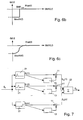
- FIG. 6a An example of a simple, but effective gain rule is depicted in Figure 6a :
- the gain as a function of the reverberation SNR increases linearly if the reverberation SNR is smaller than RIatt (i.e. if the signal power is constant or if it decreases), and the gain attains a constant maximal value if the signal power increases as a function of time.
- the maximal value is 0 (on a logarithmic scale).
- This equation contains the inversion of RIAtt(f), which can get computed at the same slow tick rate as RIAtt (f) itself, and is therefore computationally not expensive either. Likewise it can get approximated with a course lookup table method. Note also, that the max(.) operation is for robustness only, i.e. for negative values of SNR rev (t,f), which should not occur anyhow. The min(.) operation limits the gains to negative values, i.e. attenuations, such that no positive gains get applied for non-reverberation signals.
- the computed gain is then either combined with other gains computed for other means (not shown in figure 5) or independently converted back into linear domain for application onto the signal S I or a therefrom derived signal.
- FIGS. 6b and 6c show examples of further possible gain rules.
- the gain rule according to Fig. 6b simply cuts the signal off if the reverberation SNR is below a threshold value SNR THR .
- “Cut off”, in this context, means attenuation by a maximal attenuation rate MaxAtt. If the reverberation SNR is above the threshold value, the signal is not attenuated (the gain is 0 on a logarithmic scale). Other, more sophisticated stepped functions including a plurality of steps may be applied also.
- the gain rule according to Fig. 6c is, next to the one of Fig. 6a, an other example of a gain rule where the gain is a continuous function of the reverberation SNR.
- the logarithmic signal power (or level) as well as the term RIatt is computed in a plurality of frequency bands, and a gain factor is calculated in each band. Equations (1) to (5) are then all to be read as frequency dependent, as indicated by the variable f .
- Time domain or transformation based filter banks with uniform or non-uniform frequency band-width distribution for the individual bands may be used to divide the converted input signal into individual signals for each frequency band.
- transform based filterbanks comprise, but are not limited to, FFT, DCT, and Wavelet based filterbanks.
- Figure 7 very schematically depicts the embodiment where a gain factor is calculated in each frequency band.
- the converted input signal is fed to the filters 21 of the filterbank yielding a pluraltiy of input subsignals S I (f).
- a gain evaluating means 13 of the kind described above calculates a gain factor for a gain unit 11.
- Individual smoothing filter parameters may be used for each frequency band. Such individual smoothing filter parameters may be adapted to a frequency band specific room impulse attenuation value in each frequency band.
- the output sub-signals S O (f) obtained in each frequency band are added (or inverse transformed, respectively) by an adding stage 22 to provide an output signal So.
- the number of frequency bands is chosen to be between 10 and 36, however, the invention applies for any number of frequency bands.
- Frequency bands may be chosen to be uniformly spaced on a logarithmic scale.
- the following steps are applied.
- the first measured positive value of Att(t, f) is stored in a temporary store.
- Each subsequently measured value of Att(t, f) is compared with the stored value. If it is larger, the stored value is replaced by the measured value.
- the value remaining in the store after the time period I is defined to be RIatt. This procedure is repeated regularly (the repetition rate of the procedure is sometimes denoted "tick rate" in this text), and every time RIatt is evaluated anew.
- This procedure is founded on the assumption that the power signal is smooth on a time scale corresponding to T.
- the time constants of filters of the smoothing stages have to be chosen in the range of T or larger than T.
- the value Att(t,f) may be the result of an averaging of subsequent difference values.
- RIatt may be continually updated.
- Each value of Att(t, f) - evaluated according to (7) - is compared with the stored value as in the above procedure. If the measured value is higher than the stored value, the stored value is replaced by the measured value.
- the stored value is regularly lowered by an incremental value so that the system may not be trapped once the attenuation value is high, and may adapt to a situation where the hearing instrument user gets into a situation where reverberation is enhanced.
- time constants of the filters (averagers) of the smoothing stage may be adapted to the actual value of RIatt, or, via equation (3) to the value of T r , respectively. In Fig. 5, this is illustrated by a dashed arrow illustrating a feedback function. More concretely, time constants of the filters may for example be chosen to be proportional to T r and for example be between 1/2 and 1/20 of the value of T r, , preferably between 1/3 and 1/10 of the value of T r . According to a preferred embodiment, dual slope averagers are used, wherein time constants for the dual-slope filters are made adaptive in response to the room impulse attenuation values.
Landscapes
- Health & Medical Sciences (AREA)
- General Health & Medical Sciences (AREA)
- Neurosurgery (AREA)
- Otolaryngology (AREA)
- Physics & Mathematics (AREA)
- Engineering & Computer Science (AREA)
- Acoustics & Sound (AREA)
- Signal Processing (AREA)
- Circuit For Audible Band Transducer (AREA)
- Measurement Of Mechanical Vibrations Or Ultrasonic Waves (AREA)
Priority Applications (3)
| Application Number | Priority Date | Filing Date | Title |
|---|---|---|---|
| EP20040405272 EP1469703B1 (en) | 2004-04-30 | 2004-04-30 | Method of processing an acoustical signal and a hearing instrument |
| DE200460006912 DE602004006912T2 (de) | 2004-04-30 | 2004-04-30 | Verfahren zur Verarbeitung eines akustischen Signals und ein Hörgerät |
| DK04405272T DK1469703T3 (da) | 2004-04-30 | 2004-04-30 | Fremgangsmåde til behandling af et akustisk signal og et höreapparat |
Applications Claiming Priority (1)
| Application Number | Priority Date | Filing Date | Title |
|---|---|---|---|
| EP20040405272 EP1469703B1 (en) | 2004-04-30 | 2004-04-30 | Method of processing an acoustical signal and a hearing instrument |
Publications (3)
| Publication Number | Publication Date |
|---|---|
| EP1469703A2 EP1469703A2 (en) | 2004-10-20 |
| EP1469703A3 EP1469703A3 (en) | 2005-06-22 |
| EP1469703B1 true EP1469703B1 (en) | 2007-06-13 |
Family
ID=32893044
Family Applications (1)
| Application Number | Title | Priority Date | Filing Date |
|---|---|---|---|
| EP20040405272 Expired - Lifetime EP1469703B1 (en) | 2004-04-30 | 2004-04-30 | Method of processing an acoustical signal and a hearing instrument |
Country Status (3)
| Country | Link |
|---|---|
| EP (1) | EP1469703B1 (da) |
| DE (1) | DE602004006912T2 (da) |
| DK (1) | DK1469703T3 (da) |
Families Citing this family (11)
| Publication number | Priority date | Publication date | Assignee | Title |
|---|---|---|---|---|
| EP1772713A4 (en) * | 2004-07-29 | 2009-04-29 | Wakayama University | ACCORDING TO IMPULSE MEASURING PROCEDURE AND EQUIPMENT |
| DE102005037895B3 (de) * | 2005-08-10 | 2007-03-29 | Siemens Audiologische Technik Gmbh | Hörvorrichtung und Verfahren zum Bestimmen einer Information über eine Raumakustik |
| DE102008012993B4 (de) * | 2008-03-07 | 2013-02-21 | Siemens Medical Instruments Pte. Ltd. | Hörgerät mit drahtloser Signalübertragung und Verfahren zum Steuern einer Signalverarbeitung eines Hörgerätes |
| EP2596647B1 (en) | 2010-07-23 | 2016-01-06 | Sonova AG | Hearing system and method for operating a hearing system |
| JP5751110B2 (ja) | 2011-09-22 | 2015-07-22 | 富士通株式会社 | 残響抑制装置および残響抑制方法並びに残響抑制プログラム |
| DE102014218672B3 (de) | 2014-09-17 | 2016-03-10 | Sivantos Pte. Ltd. | Verfahren und Vorrichtung zur Rückkopplungsunterdrückung |
| GB2551499B (en) * | 2016-06-17 | 2021-05-12 | Toshiba Kk | A speech processing system and speech processing method |
| EP3337190B1 (en) | 2016-12-13 | 2021-03-10 | Oticon A/s | A method of reducing noise in an audio processing device |
| US10542354B2 (en) * | 2017-06-23 | 2020-01-21 | Gn Hearing A/S | Hearing device with suppression of comb filtering effect |
| DE102018210143A1 (de) | 2018-06-21 | 2019-12-24 | Sivantos Pte. Ltd. | Verfahren zur Unterdrückung eines akustischen Nachhalls in einem Audiosignal |
| CN113132882B (zh) * | 2021-04-16 | 2022-10-28 | 深圳木芯科技有限公司 | 多动态范围压扩方法和系统 |
Family Cites Families (1)
| Publication number | Priority date | Publication date | Assignee | Title |
|---|---|---|---|---|
| DK1522206T3 (da) * | 2002-07-12 | 2007-11-05 | Widex As | Höreapparat og en fremgangmsåde til at forbedre taleforståelighed |
-
2004
- 2004-04-30 DE DE200460006912 patent/DE602004006912T2/de not_active Expired - Lifetime
- 2004-04-30 EP EP20040405272 patent/EP1469703B1/en not_active Expired - Lifetime
- 2004-04-30 DK DK04405272T patent/DK1469703T3/da active
Also Published As
| Publication number | Publication date |
|---|---|
| DE602004006912D1 (de) | 2007-07-26 |
| EP1469703A3 (en) | 2005-06-22 |
| EP1469703A2 (en) | 2004-10-20 |
| DE602004006912T2 (de) | 2008-02-28 |
| DK1469703T3 (da) | 2007-10-08 |
Similar Documents
| Publication | Publication Date | Title |
|---|---|---|
| US7319770B2 (en) | Method of processing an acoustic signal, and a hearing instrument | |
| US6757395B1 (en) | Noise reduction apparatus and method | |
| US6219427B1 (en) | Feedback cancellation improvements | |
| US8351626B2 (en) | Audio amplification apparatus | |
| US8538052B2 (en) | Generation of probe noise in a feedback cancellation system | |
| KR101837331B1 (ko) | 보청기 시스템을 동작시키는 방법 및 보청기 시스템 | |
| JP6351538B2 (ja) | ディジタル音響信号用の多帯域信号プロセッサ | |
| KR101744464B1 (ko) | 보청기 시스템에서의 신호 프로세싱 방법 및 보청기 시스템 | |
| JP2003516003A (ja) | 信号処理技術を組込んだ補聴器 | |
| EP1469703B1 (en) | Method of processing an acoustical signal and a hearing instrument | |
| US11195539B2 (en) | Forced gap insertion for pervasive listening | |
| TWI623234B (zh) | 助聽器及其自動分頻濾波增益控制方法 | |
| US7756276B2 (en) | Audio amplification apparatus | |
| EP2869600B1 (en) | Adaptive residual feedback suppression | |
| JP2002223182A (ja) | 反響消去方法、その装置、そのプログラム及びその記録媒体 | |
| RU2589298C1 (ru) | Способ повышения разборчивости и информативности звуковых сигналов в шумовой обстановке | |
| EP3531719B1 (en) | Dereverberation device and hearing aid | |
| JP2004032387A (ja) | ハウリング制御装置及び補聴器 | |
| CN117714956B (zh) | 确定听力仪器的声学特性 | |
| Pandey et al. | Improving adaptive feedback cancellation in digital hearing aids through offending frequency suppression | |
| de Perez et al. | Noise reduction and loudness compression in a wavelet modelling of the auditory system | |
| Adrian et al. | An acoustic noise suppression system with reduced musical artifacts |
Legal Events
| Date | Code | Title | Description |
|---|---|---|---|
| PUAI | Public reference made under article 153(3) epc to a published international application that has entered the european phase |
Free format text: ORIGINAL CODE: 0009012 |
|
| AK | Designated contracting states |
Kind code of ref document: A2 Designated state(s): AT BE BG CH CY CZ DE DK EE ES FI FR GB GR HU IE IT LI LU MC NL PL PT RO SE SI SK TR |
|
| AX | Request for extension of the european patent |
Extension state: AL HR LT LV MK |
|
| PUAL | Search report despatched |
Free format text: ORIGINAL CODE: 0009013 |
|
| AK | Designated contracting states |
Kind code of ref document: A3 Designated state(s): AT BE BG CH CY CZ DE DK EE ES FI FR GB GR HU IE IT LI LU MC NL PL PT RO SE SI SK TR |
|
| AX | Request for extension of the european patent |
Extension state: AL HR LT LV MK |
|
| RIC1 | Information provided on ipc code assigned before grant |
Ipc: 7H 04R 25/00 A Ipc: 7G 10L 21/02 B |
|
| 17P | Request for examination filed |
Effective date: 20051203 |
|
| GRAP | Despatch of communication of intention to grant a patent |
Free format text: ORIGINAL CODE: EPIDOSNIGR1 |
|
| AKX | Designation fees paid |
Designated state(s): CH DE DK LI |
|
| GRAS | Grant fee paid |
Free format text: ORIGINAL CODE: EPIDOSNIGR3 |
|
| GRAA | (expected) grant |
Free format text: ORIGINAL CODE: 0009210 |
|
| AK | Designated contracting states |
Kind code of ref document: B1 Designated state(s): CH DE DK LI |
|
| REG | Reference to a national code |
Ref country code: CH Ref legal event code: EP |
|
| REF | Corresponds to: |
Ref document number: 602004006912 Country of ref document: DE Date of ref document: 20070726 Kind code of ref document: P |
|
| REG | Reference to a national code |
Ref country code: CH Ref legal event code: NV Representative=s name: FREI PATENTANWALTSBUERO AG |
|
| REG | Reference to a national code |
Ref country code: DK Ref legal event code: T3 |
|
| PLBE | No opposition filed within time limit |
Free format text: ORIGINAL CODE: 0009261 |
|
| STAA | Information on the status of an ep patent application or granted ep patent |
Free format text: STATUS: NO OPPOSITION FILED WITHIN TIME LIMIT |
|
| 26N | No opposition filed |
Effective date: 20080314 |
|
| PGFP | Annual fee paid to national office [announced via postgrant information from national office to epo] |
Ref country code: CH Payment date: 20140428 Year of fee payment: 11 |
|
| PGFP | Annual fee paid to national office [announced via postgrant information from national office to epo] |
Ref country code: DK Payment date: 20140425 Year of fee payment: 11 |
|
| REG | Reference to a national code |
Ref country code: DK Ref legal event code: EBP Effective date: 20150430 |
|
| REG | Reference to a national code |
Ref country code: CH Ref legal event code: PL |
|
| PG25 | Lapsed in a contracting state [announced via postgrant information from national office to epo] |
Ref country code: CH Free format text: LAPSE BECAUSE OF NON-PAYMENT OF DUE FEES Effective date: 20150430 Ref country code: LI Free format text: LAPSE BECAUSE OF NON-PAYMENT OF DUE FEES Effective date: 20150430 |
|
| PG25 | Lapsed in a contracting state [announced via postgrant information from national office to epo] |
Ref country code: DK Free format text: LAPSE BECAUSE OF NON-PAYMENT OF DUE FEES Effective date: 20150430 |
|
| REG | Reference to a national code |
Ref country code: DE Ref legal event code: R084 Ref document number: 602004006912 Country of ref document: DE |
|
| P01 | Opt-out of the competence of the unified patent court (upc) registered |
Effective date: 20230530 |
|
| PGFP | Annual fee paid to national office [announced via postgrant information from national office to epo] |
Ref country code: DE Payment date: 20230427 Year of fee payment: 20 |
|
| REG | Reference to a national code |
Ref country code: DE Ref legal event code: R071 Ref document number: 602004006912 Country of ref document: DE |