EP1469705B1 - Commande du fondu et de l'intensité d'un signal à effet spatial - Google Patents
Commande du fondu et de l'intensité d'un signal à effet spatial Download PDFInfo
- Publication number
- EP1469705B1 EP1469705B1 EP04100252A EP04100252A EP1469705B1 EP 1469705 B1 EP1469705 B1 EP 1469705B1 EP 04100252 A EP04100252 A EP 04100252A EP 04100252 A EP04100252 A EP 04100252A EP 1469705 B1 EP1469705 B1 EP 1469705B1
- Authority
- EP
- European Patent Office
- Prior art keywords
- control region
- control
- surround
- signals
- input signals
- Prior art date
- Legal status (The legal status is an assumption and is not a legal conclusion. Google has not performed a legal analysis and makes no representation as to the accuracy of the status listed.)
- Expired - Lifetime
Links
Images



Classifications
-
- H—ELECTRICITY
- H04—ELECTRIC COMMUNICATION TECHNIQUE
- H04S—STEREOPHONIC SYSTEMS
- H04S7/00—Indicating arrangements; Control arrangements, e.g. balance control
- H04S7/30—Control circuits for electronic adaptation of the sound field
-
- H—ELECTRICITY
- H04—ELECTRIC COMMUNICATION TECHNIQUE
- H04R—LOUDSPEAKERS, MICROPHONES, GRAMOPHONE PICK-UPS OR LIKE ACOUSTIC ELECTROMECHANICAL TRANSDUCERS; ELECTRIC HEARING AIDS; PUBLIC ADDRESS SYSTEMS
- H04R2499/00—Aspects covered by H04R or H04S not otherwise provided for in their subgroups
- H04R2499/10—General applications
- H04R2499/13—Acoustic transducers and sound field adaptation in vehicles
-
- H—ELECTRICITY
- H04—ELECTRIC COMMUNICATION TECHNIQUE
- H04S—STEREOPHONIC SYSTEMS
- H04S2400/00—Details of stereophonic systems covered by H04S but not provided for in its groups
- H04S2400/13—Aspects of volume control, not necessarily automatic, in stereophonic sound systems
Definitions
- This invention relates to audio systems, and more particularly to fading and signal level controls for surround sound audio systems.
- Audio systems with surround sound features are prevalent in theaters, home entertainment systems, and automobiles.
- surround sound features enhance the overall listening experience by increasing the aural stimulations associated with music, motion picture soundtracks, and other audio performances.
- the surround sound capability is provided by using a collection of spatially diverse speakers.
- primary (or front) speakers are located in front of the listener or audience and surround sound speakers are located behind and/or to the sides of the listener or audience.
- Surround sound processing of an audio input controls the signal that is sent to each speaker and causes each speaker to produce a different audio output.
- listeners may be presented with the sensation of being seemingly surrounded by sound and/or with the sensation of sound originating from a particular direction.
- US2001/022841 discloses a multi-channel sound system wherein appropriate output (balance and fader) control can be conducted without adversely affecting the program contents, and a sound system, which can reproduce a plurality of channel signals including at least left and right front channels and a center channel for forward-placed speakers, comprises a gain controller to control the gain of either left or right channel signal and a gain controller to control the gain of the center channel signal depending on the gain control of the left or right channel signal.
- a system for controlling fading and surround level for a surround sound system with a plurality of input signals and a plurality of spatially diverse transducers in a listening environment in which a signal processor is operable to process each of the plurality of input signals and provide each processed signal to a corresponding transducer in a first mode and to mix at least two of the input signals to generate a mixed signal for at least one of the transducers and provide the mixed signal to the corresponding transducer in a second mode; characterized by a memory for storing a plurality of control parameters for adjusting the relative strength of the input signals, wherein the control parameters are indexed according to a plurality of defined positions in a first control region and a second control region; a controller for operating in the first control region and the second control region; wherein the signal processor operates in the first mode based on the control parameters when the controller is operating in the first control region; and wherein the signal processor operates in the second mode based on the control parameters when the controller is operating in the second
- a first control region may control a strength of one or more audio surround source signals relative to one or more audio front source signals.
- a second control region may control mixing of the audio surround source signals and the audio front source signals in addition to controlling the relative strengths of the audio surround source signals and the audio front source signals.
- a relative strength of the selected input signals may be adjusted, the adjusted input signals mixed, and the mixed input signals applied to the transducer.
- Implementations may include one or more of the following features.
- the first control region and the second control region may include a discrete surround sound level control region as well as a forward fading control region and/or a backward fading control region.
- a first transition region may separate the surround sound level control region from the forward fading control region, and a second transition region may separate the surround sound level control region from the backward fading control region.
- the first transition region may include multiple positions for transitioning the adjusted input signals from the surround sound level control region to the forward fading control region, and the second transition region may include multiple positions for transitioning the adjusted input signals from the surround sound level control region to the backward fading control region.
- the first control region and the second control region may be further divided into multiple possible positions for a control device. Adjacent positions may be separated by a discrete step size.
- the discrete step size may represent a change by a predetermined value of the adjusted input signal strength relative to an original input signal strength.
- Adjusting the relative strength of the selected input signals may further include obtaining control parameters corresponding to the selected input signals and adjusting the signal strength of the selected input signals based on the control parameters.
- the control parameters may be stored in a table. Obtaining control parameters may further include setting the control parameters to satisfy predetermined criteria, which may relate to optimizing a perceived sound quality and/or maintaining a constant overall system output level.
- the invention also includes a method for controlling a surround sound system with a plurality of input signals and a plurality of spatially diverse transducers in a listening environment, including in a first mode, adjusting a relative strength of at least one of a plurality of input signals with respect to other input signals, and in a second mode, adjusting a relative output level of at least one of the spatially diverse transducers with respect to other transducers, wherein the signal provided to at least one of the spatially diverse transducers includes components of at least two of the input signals, characterized in by defining a plurality of control regions, each of which corresponds to a distinct position range on a single degree of freedom control; operating in the first mode when the control is in a first control region of the plurality of control regions; and operating in the second mode when the control is in a second control region of the plurality of control regions.
- Implementations may include one or more of the following features.
- the first control region may include a surround level control region.
- a relative strength of one or more surround signals may be adjusted when operating in the surround level control region.
- the second control region may include a front-rear fading control region. A relative output level of one or more transducers with respect to other transducers may be adjusted when operating in the second control region.
- the second control region may be further divided into a backward fading control region and a forward fading control region.
- a system for controlling fading and surround level may be provided for a surround sound system with multiple input signals and multiple spatially diverse transducers in a listening environment
- the system may include a memory for storing control parameters that are used for adjusting a relative strength of input signals.
- the control parameters may be indexed according to defined positions in a first control region and a second control region.
- the system may also include a controller for operating in the first control region and the second control region.
- a signal processor may be operable to process each of the input signals based on the control parameters and to provide each processed signal to a corresponding transducer when the controller is operating in the first control region.
- the signal processor may also be operable to mix two or more of the input signals based on the control parameters to generate a mixed signal for each transducer and to provide the mixed signal to the corresponding transducer when the controller is operating in the second control region.
- the listening environment may be an automotive listening environment or a room (e.g., in a theater, home, or other building).
- the signal processor may be operable to process each input signal by selecting one or more input signals and adjusting a strength of the selected input signals.
- the controller may be operable to tune to defined positions in the control regions.
- the controller may comprise a remote controller.
- the controller may also be mounted in the listening environment.
- the controller may comprise a rotary switch controller or an increment/decrement controller.
- a surround sound system with multiple input signals and multiple spatially diverse transducers in a listening environment may include a controller for operating in multiple control regions.
- a signal processor may be provided for adjusting a relative strength of one or more input signals with respect to other input signals when the controller is operating in a first control region.
- the signal processor may further adjust relative output levels of one or more transducers with respect to other transducers when the controller is operating in a second control region.
- the relative output levels of one or more transducers may include components of two or more of the input signals when the controller is operating in the second control region.
- the first control region may include a surround level control region for adjusting a relative strength of one or more surround signals.
- the second control region may include a front-rear fading control region for adjusting relative output levels between a front set of transducers and a rear set of transducers.
- the second control region may be further divided into a front-to-rear backward fading control region and a rear-to-front forward fading control region.
- the controller may be a remote controller or may be mounted in the listening environment.
- a system and method for controlling a surround sound system with multiple input signals and multiple spatially diverse transducers may involve defining a first control region and a second control region for a control device and receiving input signals.
- a first set of functions may be performed.
- relative strengths of the input signals may be selectively adjusted by adjusting a first subset of the input signals relative to a second subset of the input signals.
- the adjusted input signals may be applied to transducers, and each of the transducers may receive a corresponding number of input signals.
- a second set of functions may be performed.
- the relative strengths of the input signals may be selectively adjusted, and the adjusted input signals may be applied to the transducers.
- One or more of the transducers may receive a different number of input signals than when the control device is operating in the first control region.
- Implementations may include one or more of the following features.
- the first subset of input signals may include one or more surround audio source signals
- the second subset of input signals may include one or more front audio source signals.
- the transducers may include one or more front transducers and one or more surround transducers. Each front transducer may receive one or more front audio source signals and each surround transducer may receive one or more surround audio source signals when the control device is operating in the first control region. When the control device is operating in the second control region, one or more front transducers may receive components of a front audio source signal or signals and a surround audio source signal or signals.
- one or more surround transducers may receive components of a front audio source signal or signals and a surround audio source signal or signals when the control device is operating in the second control region.
- a system and method for controlling a surround sound system with multiple input signals and multiple spatially diverse transducers may involve defining a first control region and a second control region for a control device and receiving input signals.
- first control region relative strengths of a first number of the input signals may be selectively adjusted, and the adjusted input signals may be applied to transducers.
- second control region relative strengths of a second, different number of the input signals may be selectively adjusted, and the adjusted input signals may be applied to the transducers.
- Implementations may include one or more of the following features.
- the first number of input signals may include one or more surround audio source signals.
- the second number of input signals may include one or more surround audio source signals and one or more front audio source signals.
- Applying the adjusted input signals to the transducers when the control device is operating in the second control region may involve applying one or more adjusted surround audio source signals and one or more adjusted front audio source signals to a surround transducer.
- Applying the adjusted input signals to the transducers when the control device is operating in the second control region may also involve applying one or more adjusted surround audio source signals and one or more adjusted front audio source signals to a front transducer.
- a first function may be performed on a first set of signals over a first range of control positions, and one or more other functions may be performed on another set of signals in other ranges of control positions.
- the number of signals controlled in each range may be different.
- a single control device may be used to control both surround signal level and image fader functionality in a surround sound application.
- the control device performs surround signal level control over a first range of control operation, and performs a fader function over one or more other ranges of control operation.
- the control device operates only on the surround signal or signals over a portion of an operating range for the control device, and operates on the surround signals and other signals (which may include, e.g., front left, center, and front right signals) over other portions of the operating range.
- the control device accomplishes both functions in a natural and intuitive manner.
- the disclosed system and techniques will be described and illustrated assuming an automotive listening environment. However, the techniques may be applicable to other types of listening environments, such as a living room, theater, and the like.
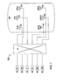
- FIG. 1 shows a block diagram of a multi-channel discrete surround sound system in an automotive listening environment.
- the surround sound system 150 uses a plurality of discrete surround sound source signals corresponding to a front left (FL) channel 10, a front right (FR) channel 20, a center (C) channel 30, a surround left (SL) channel 40, a surround right (SR) channel 50, and a bass or Low Frequency Effects (LFE) channel 60.
- FL front left
- FR front right
- C center
- SL surround left
- SR surround right
- LFE Low Frequency Effects
- the number of source signal channels may vary.
- the surround sound system 150 may not include a center channel 30 and/or an LFE channel 60.
- the surround sound system 150 may include a surround center channel (not shown).
- the number of source signal channels may be smaller than six or larger than six.
- the discrete signals 10-60 are received by a signal processor 70 for operating on the signals 10-60.
- the signal processor 70 may be implemented in the form of a digital signal processor (DSP) or in analog circuitry.
- DSP digital signal processor
- the signal processor 70 performs one or more functions on the various input signals 10-60 to create output signals.
- One function that may be performed by the signal processor 70 is alteration of signal gain.
- the signal processor 70 may either attenuate or boost (in either absolute or relative terms) one or more of signals 10-60 based on selected control parameters, as will be described in more detail below.
- the signals 10-60 may be mixed together in some fashion within signal processor 70, with variable relative or absolute gain.
- Signal mixing takes as input a plurality of input signals, mixes together one or more subsets of the input signals, and generates a plurality of output signals.
- Mixing may include attenuating or boosting the relative level of the input signal subsets to be mixed and summing together the adjusted input signals.
- Some or all of the output signals may contain components of multiple (i.e., more than one) input signals.
- the number of input signals may differ from the number of output signals. If the number of output signals is smaller than the number of input signals, the process is referred to as down-mixing. If the number of output signals is greater than the number of input signals, the process is referred to as up-mixing.
- the signal processor 70 may perform still other functions on the various input signals to create the output signals. For example, the difference between a pair of signals could be taken and output as a signal.
- the described techniques are not limited in the functions that can be performed on the input signals and are not limited in the number of input signals or output signals that may be present.
- the output signals from the signal processor 70 may be selectively sent to a plurality of spatially diverse loudspeakers.
- the loudspeakers may include a front left speaker (FL-S) 80, a center speaker (C-S) 90, a front right speaker ( FR-S) 100 , a surround left speaker (SL-S) 110, a low frequency effects speaker (LFE-S) 120, and a surround right speaker (SR-S) 130.
- the various speakers 80-130 may be installed in a vehicle 140. Similar to the number of source signals, the number of speakers can also be smaller than or larger than six.
- control parameters that may be used to adjust the input (source) signals, with or without mixing, may be selected depending on a variety of factors, such as the location of the loudspeakers and whether the purpose of the signal processing is for surround sound level control or image fading control.
- the control parameters may also depend on the acoustic characteristics of the listening environment.
- FIG. 2 shows a rotary control diagram for a single degree of freedom controller that may be used in a surround sound system.
- the described techniques are not restricted to a rotary control device, however.
- Other controls such as a slider, or +/- (increment/ decrement control) control set, may also be implemented.
- the control device may include some type of potentiometer for varying an analog signal or control voltage, or may be some type of encoder that outputs a digital code depending on position or actuation of the control device.
- a digital encoder (which may be rotary, linear, increment/decrement, or some other type of control device) may be used for digital (DSP) implementations.
- the control device can be in the form of a remote control or a controller mounted somewhere in the listening environment.
- the control device may also be located on a component of the surround sound system, such as the control interface unit for a vehicle audio system.
- a component of the surround sound system such as the control interface unit for a vehicle audio system.
- the total control region for the rotary control device is divided into a plurality of control regions.
- the rotary control device includes five control regions: a surround level control region 205 between positions 5 and 11 clockwise, a rear fading control region 210 between positions 12 and 15 clockwise, a front fading control region 215 between positions 1 and 4 clockwise, a first transition region 220 between positions 11 and 12 clockwise, and a second transition region 225 between positions 4 and 5 clockwise.
- a surround level control region 205 between positions 5 and 11 clockwise
- a rear fading control region 210 between positions 12 and 15 clockwise
- a front fading control region 215 between positions 1 and 4 clockwise
- a first transition region 220 between positions 11 and 12 clockwise
- a second transition region 225 between positions 4 and 5 clockwise.
- the surround sound level control region 205 could be located between positions 4 and 12 clockwise, and front fading and rear fading control regions 210 and 215 could be correspondingly smaller.
- the control regions could also be divided up asymmetrically, instead of symmetrically as shown in FIG. 2 . Greater or fewer numbers of tuning steps (a total of 15 are shown in FIG. 2 ) may also be used. In some implementations, the number of tuning steps may be sufficiently large that the difference between adjacent tuning steps is virtually imperceptible even when the entire range of tuning steps produces noticeably different audible results.
- some implementations may not include transition regions 220 and 225 and/or may include only one fading control region.
- each clockwise rotation step may increase the surround signal level by 1.5dB.
- the surround level control region 205 may simultaneously control a single monophonic surround signal, a stereo pair of surround signals, or multi-channel surround signal levels (e.g., left surround, left center surround, right center surround, and right surround, as might be present in a 7.1 channel implementation).
- a total level change (increase) of 9 dB (6*1.5) could be produced by clockwise rotation of the rotary control device from position 5 to position 11.
- position 8 may correspond to a 0db surround level adjustment relative to the original input surround signals
- position 11 may correspond to a +4.5dB adjustment relative to position 8 (each step, such as from positions 8 to 9, increases the level by 1.5 dB)
- position 5 may correspond to -4.5dB adjustment relative to position 8 (each step, such as from positions 8 to 7, decreases the level by 1.5 dB).
- the step sizes described here are used for illustrative purposes and, in actual implementations, can be varied as desired. Additionally, the level change with each step change need not be constant. The level change when moving from position 8 to position 9 may be different from the level change when moving from position 9 to position 10, and so on.
- the output level of the front speakers (FL-S 80, FR-S 100, and C-S 90) with respect to the rear speakers (SL-S 110, SR-S 130, and LFE-S 120) may be adjusted for each tuning step. This adjustment may be accomplished by operating on the signals that are applied to the different speakers. A different function may be performed when the control device is actuated over the rear fading region 210 portion of the rotary control device's operating range than is performed in the surround level control region 205 (e.g., over the range from positions 5 to 11). Furthermore, the rear fading control region 210 may control a different set of signals (e.g., levels of more than just surround signals may be adjusted).
- clockwise rotation of the control device in the rear fading region 210 may cause the signals fed to the rear speakers to be stronger than the signals fed to the front speakers (i.e., a rear fade function).
- the signals fed to the rear speakers may have components of the left front, center, and right front input signals.
- the signals fed to the front speakers may also contain information from the surround input signals.
- the signals fed to the front and/or rear speakers may also contain information from the low frequency effects input signals.
- fading can be accomplished by: 1) keeping signals fed to the front speakers unchanged and boosting signals fed to the rear speakers; 2) attenuating signals fed to the front speakers and keeping signals fed to the rear speakers unchanged; 3) attenuating signals fed to the front speakers and boosting signals fed to the rear speakers.
- the output level of the rear speakers (SL-S 110, SR-S 130, and LFE-S 120) with respect to the front speakers (FL-S 80, FR-S 100, and C-S 90) may be adjusted for each tuning step. This adjustment may be accomplished by operating on the signals that are applied to the different speakers.
- a different function may be performed when the control device is actuated over the front fading region 215 portion of the rotary control device's operating range than is performed in the surround level control region 205 (e.g., over the range from positions 5 to 11) and the rear fading region 210 (e.g., over the range from positions 12 to 15).
- the front fading control region 215 may control a different set of signals.
- the signals fed to the front speakers may be stronger than the signals fed to the rear speakers (i.e., a front fade function).
- the signals fed to the front speakers may have components of the left surround and right surround input signals.
- the signals fed to the rear speakers may also contain information from the front input signals.
- the signals fed to the front and/or rear speakers may also contain information from the low frequency effects input signals.
- the combination of signals may be performed in a different way for operation in the front fading region 215 as compared to operation in the rear fading region 210. For example, operation in the rear fading region 210 may result in signals being fed to the rear speakers that have significant front speaker components, while operation in the front fading region 215 may result in signals being fed to the front speakers that have relatively small surround speaker components.
- fading can be accomplished by: 1) keeping signals fed to the rear speakers unchanged and boosting signals fed to the front speakers; 2) attenuating signals fed to the rear speakers and keeping signals fed to the front speakers unchanged; 3) attenuating signals fed to the rear speakers and boosting signals fed to the front speakers.
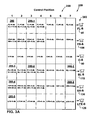
- FIG. 3 shows an illustrative control parameter chart 250 of the various input signals and signal levels applied to each speaker for each position of the control device shown in FIG. 2 .
- the control device may be used for a surround sound application in a vehicle, for example.
- the surround signal level fed to selected speakers is controlled over a first region of operation. Over other regions, various signals are mixed (summed) together using varying relative and absolute levels and then fed to selected speakers.
- the control parameter chart 250 of FIG. 3 provides the signal mixing and corresponding control parameter values for a six speaker surround sound configuration, as shown in FIG. 1 , that uses the rotary control device depicted in FIG. 2 .
- a horizontal axis 255 of the chart 250 represents the control position 1-15 as shown in FIG. 2 .
- a vertical axis 260 of the chart 250 represents the six speakers (FL-S 80, FR-S 100, C-S 90, SL-S 110, SR-S 130, and LFE-S 120), as shown in FIG. 1 .
- the chart 250 represents one possible implementation of a surround level and fading control system. Other signal mixing combinations and parameter values may be used.
- Each cell in FIG. 3 shows the discrete signals that are mixed together for each speaker and each control device position.
- Each cell also shows control parameters that are to be applied to the discrete signals for each speaker and each control device position.
- the control parameters represent gain changes relative to the original input signals. For example, for the front left speaker 80, when the control is set at position 1 (see FIG. 2 ), the discrete front left and surround left signals (FL and SL) are processed with particular gain changes, 0 dB and -1.5 dB respectively (as shown in cell 280), and then mixed together (summed). The mixed signal is fed to the front left speaker 80. For the left surround speaker 110, when the control device is set at position 12 (see FIG.
- discrete front left, center, and surround left signals FL, C, and SL
- discrete front left, center, and surround left signals FL, C, and SL
- specific gain changes -1.5 dB each (as shown in cell 290)
- the mixed signal is then fed to the left surround speaker 110.
- the value of the control parameters may be selected in accordance with certain criteria that relate to, for example, optimizing perceived sound quality and/or maintaining a constant overall system output level.
- the surround input signals and the front input signals are preserved as discrete. That is, no signal mixing takes place, and only gain changes of surround signals relative to the other signals are implemented.
- the control device is set at position 8, all of the discrete signals are passed to the corresponding speaker without any gain change.
- every clockwise rotation step increases the surround signal level or levels (SL and SR signals) by a predetermined amount, such as 1.5dB.
- the left and right surround signals (SL and SR) will have a gain increase of 1.5dB (see cells 287-1 and 287-2) while other discrete signals are passed through without modifications.
- Each additional clockwise rotation step results in a further gain increase for the left and right surround signals.
- both the left and right surround signals (SL and SR) have a 2 dB gain change when moving from position 10 to position 11.
- signal boosts or attenuations provided by each control step need not be constant.
- the values used in any particular implementation may be selected depending on expected system and listening environment specifications.
- every counterclockwise rotation step decreases the left and right surround signal level or levels (SL and SR signals) by a predetermined amount, such as 1.5dB.
- the left and right surround signals (SL and SR) have a gain change of -1.5dB (see cells 288-1 and 288-2) and all other signals are passed through without modification. Additional counterclockwise rotation steps results in a further gain attenuation for the left and right surround signals.
- the audio image is faded to the rear with each clockwise step rotation.
- the audio signals passed through the signal processing associated with the control device are no longer maintained as discrete.
- the audio does not represent discrete multi-channel surround sound, but instead input signals are mixed in some manner. However, all of the surround sound information is still present.
- every clockwise step rotation makes signals fed to the rear speakers 110 and 130 (SL-S and SR-S) relatively stronger than signals fed to the front speakers 80, 90, and 100 (FL-S, FR-S and C-S).
- SL-S and SR-S signals fed to the rear speakers 110 and 130
- FL-S, FR-S and C-S signals fed to the front speakers 80, 90, and 100
- adjusting relative signal strength between the front speakers and the rear speakers such as: 1) keeping signals fed to the front speakers unchanged and boosting signals fed to the rear speakers; 2) attenuating signals fed to the front speakers and keeping signals fed to the rear speakers unchanged; 3) attenuating signals fed to the front speakers and boosting signals fed to the rear speakers. Any of these methods, alone or in combination, may be used to effect a fade function.
- the illustrated example keeps the strength of the signals fed to the rear speakers unchanged and decreases the strength of the signals fed to the front speakers, for clockwise step rotations in the region from positions 12 to 15.
- the discrete front left signal (FL) is adjusted by being attenuated by 8 dB
- the discrete surround left signal (SL) is adjusted by being attenuated by 10 dB
- the two adjusted signals are mixed and fed to the front left speaker 80 (FL-S) (as shown at cell 295-1).
- the front left and surround left signals (FL and SL) may be attenuated by the same magnitude, such as 8 dB. In such a case, the signals could be mixed together before being attenuated, rather than after.
- the implementation can feed the front left and surround left signals (FL and SL) to the front left speaker (FL-S) without any pre-adjustment.
- the output of the front left speaker 80 may be adjusted to achieve the same 8db attenuation on both signals FL and SL.
- the signal adjustments for a mixing signal scenario can be performed either in the signal processor or in the speakers to which the signals are fed if the adjustment amounts for all the mixed signals are the same.
- the signal adjustments for a discrete signal scenario (such as for the signal fed to the center speaker 90 (C-S)) can be performed either in the signal processor or in the speakers to which the signal is fed.
- the discrete front left signal (FL) is adjusted by being attenuated by 1.5 dB
- discrete center signal (C) is adjusted by being attenuated by 1.5 dB
- discrete surround left signal (SL) is adjusted by being attenuated by 1.5 dB
- the three adjusted signals are mixed and fed to the left surround speaker 110 (SL-S) (as shown at cell 295-2).
- the audio image is faded to the front with each counterclockwise step rotation.
- the audio signals that pass through the signal processing associated with the control device are not maintained as discrete.
- the audio is not discrete multi-channel surround sound, but instead uses input signals that are mixed in some manner. However, all of the surround sound information is still present.
- every counterclockwise step rotation makes signals fed to the front speakers 80, 90, and 100 (FL-S, FR-S and C-S) relatively stronger than signals fed to the rear speakers 110 and 130 (SL-S and SR-S).
- the strength of the front signals (FL and FR) fed to the front speakers remains unchanged while the strength of the surround signals (SL and SR) fed to the front speakers generally increases with each counterclockwise step rotation.
- the strength of the signals fed to the rear speakers is decreased for counterclockwise step rotations in the region from position 4 to 1.
- a discrete front left signal (FL) passes through without any adjustment (having 0 dB control parameter), discrete surround left signal (SL) is adjusted by being attenuated by 3 dB, and the two adjusted signals are mixed and fed to the front left speaker 80 (FL-S) (as shown in cell 285-1).
- the front left and surround signals FL and SL could be attenuated by the same magnitude, such as 3 dB. In this case, the signals could be mixed together before being attenuated, rather than after.
- the discrete front left signal (FL) is adjusted by being attenuated by 9 dB
- the discrete surround left signal (SL) is adjusted by being attenuated by 13 dB
- the adjusted signals are mixed and fed to the left surround speaker 110 (SL-S) (as shown in cell 285-2).
- the transition region between the surround level control region and the rear fading control region serves as a transition region between the surround signal level and rear fade control functions.
- the transition region between the surround level control region and the front fading control region serves as a transition region between the surround signal level and front fade control functions.
- FIG. 4 shows a representative diagram of a finer resolution control scheme 300 for the transition region between the surround level control region and the rear fading control region.
- a similar control scheme may be used for the transition region between the surround level control region and the front fading control region.
- the finer resolution control scheme 300 includes a plurality of intermediate control positions 1', 2', ..., and 3'. Each intermediate control position may represent an intermediate level of mixing and an intermediate system output level with respect to positions 11 and 12.
- FIG. 5 shows an illustrative control parameter chart 500 of the various input signals and signal levels applied to each speaker for each intermediate position of the control device shown in FIG. 4 .
- the chart represents an example of signal mixing and corresponding gain control parameters values for the transition region between positions 11 and 12. For simplicity, it is assumed that there are three finer intermediate steps between positions 11 and 12, although other numbers of intermediate control positions may be used.
- a horizontal axis 505 of the chart 500 represents the intermediate control positions 1'-3' as shown in FIG. 4 .
- a vertical axis 510 of the chart 500 represents the six speakers (FL-S 80, FR-S 100, C-S 90, SL-S 110, SR-S 130, and LFE-S 120) as shown in FIG. 1 .
- the chart 500 represents one possible implementation of a transition region for a surround level and fading control system. Other signal mixing combinations and parameter values may be used.
- the discrete front left signal (FL) when transitioning from position 11 to 12, the discrete front left signal (FL) will be gradually attenuated from 0 dB at position 11 (as shown at cell 600-1) to -4 dB at position 12 (as shown at cell 600-2).
- the surround left signal (SL) is gradually mixed in with the discrete front left signal (FL) initially with -60 dB of relative gain (so that it is barely audible) at position 1', and the surround left signal gain is increased with each clockwise step rotation to reach -6 dB at position 12.
- the surround left signal (SL) when transitioning from position 11 to 12 in a clockwise direction, the surround left signal (SL) may be gradually attenuated from 5 dB relative gain at position 11 (as shown at cell 610-1) to -1.5 dB gain at position 12.
- front left and center signals (FL and C) are gradually mixed in with the discrete surround left signal (SL).
- discrete front left and center signals (FL and C) are gradually mixed in starting with -60 dB relative gain at position 1', and gains for the front left and center signals (FL and C) are increased with each clockwise step rotation to -1.5 dB at position 12 (as shown at cell 610-2).
- Other possible implementations of the transition region are possible. For example, other parameter values may be used and alternative mixing methods may be used.
- the second transition region between surround level control and forward fading control may use a transition method similar to that shown in FIG. 5 .
Landscapes
- Physics & Mathematics (AREA)
- Engineering & Computer Science (AREA)
- Acoustics & Sound (AREA)
- Signal Processing (AREA)
- Stereophonic System (AREA)
- Circuit For Audible Band Transducer (AREA)
Claims (26)
- Système pour contrôler le fondu et l'intensité d'un signal à effet spatial avec une multitude de signaux d'entrée et une pluralité de transducteurs (80-130) spatialement séparés dans un environnement d'écoute, dans lequel un processeur de signaux (70) peut travailler pour traiter chacun de la multitude des signaux d'entrée et pour fournir chaque signal traité à un transducteur correspondant (80-130) dans un premier mode de travail et mélanger au moins deux des signaux d'entrée pour générer un signal mélangé pour au moins un des transducteurs et délivrer le signal mélangé à un transducteur correspondant dans un deuxième mode de travail; caractérisé par
une mémoire pour mémoriser une multitude de paramètres de contrôle pour ajuster la force relative des signaux d'entrée, où les paramètres de contrôle sont indexés selon la multitude de positions prédéfinies dans une première zone de contrôle (205) et dans une deuxième zone de contrôle (210, 510) ;
une unité de contrôle (200) pour opérer dans la première zone de contrôle et dans la deuxième zone de contrôle ;
où le processeur de signaux (70) travaille dans le premier mode de travail basé sur les paramètres de contrôle quand l'unité de contrôle travaille dans la première zone de contrôle (205) ; et
où le processeur de signaux travaille dans un deuxième mode de travail basé sur les paramètres de contrôle quand l'unité de contrôle travaille dans une deuxième zone de contrôle (210, 215). - Système selon la revendication 1, où l'environnement d'écoute comprend un environnement d'écoute automobile.
- Système selon la revendication 1, où ledit environnement d'écoute comprend une chambre.
- Système selon l'une quelconque des revendications 1 à 3, où le processeur de signaux (70) travaille pour traiter chacun des signaux d'entrée par choisir au moins un signal d'entrée et par ajuster une force des signaux d'entrée choisis.
- Système selon l'une quelconque des revendications 1 à 4, où l'unité de contrôle (200) travaille pour ajuster finement une de la multitude des positions prédéfinies dans la multitude des zones de contrôle.
- Système selon la revendication 5, où l'unité de contrôle (200) comprend une commande à distance.
- Système selon la revendication 5, où l'unité de contrôle (200) est prévue dans l'environnement d'écoute.
- Système selon la revendication 5, où l'unité de contrôle (200) comprend soit un commutateur rotatif ou une unité de contrôle à incrément/décrément.
- Système selon la revendication 1, où la première zone de contrôle (205) comprend une zone de contrôle à effet spatial pour ajuster une force relative d'au moins un signal à effet spatial.
- Système selon la revendication 1, où la deuxième zone de contrôle comprend une zone de contrôle (210, 215) de fondu avant-arrière pour ajuster des niveaux de sortie relatifs entre un set avant de transducteurs et un set arrière de transducteurs.
- Système selon la revendication 10, où la deuxième zone de contrôle est divisée en plus dans une zone de contrôle de fondu arrière avant-vers-arrière et dans une zone de contrôle de fondu avant arrière-vers-avant.
- Procédé pour contrôler le système à effet spatial (150) avec une multitude de signaux d'entrée et une pluralité de transducteurs (80, 130) spatialement séparés dans un environnement d'écoute, incluant, dans un premier mode de travail, ajuster une force relative d'au moins un d'une multitude de signaux d'entrée par rapport à d'autres signaux d'entrée, et, dans un deuxième mode de travail, ajuster un niveau de sortie relatif d'au moins un de la pluralité de transducteurs (80, 130) spatialement séparés par rapport à d'autres transducteurs, où le signal fourni pour au moins un des transducteurs spatialement séparés inclut des composantes d'au moins deux des signaux d'entrée ; caractérisé par
définir une multitude de zones de contrôle (205, 210, 215), où chacune correspond à une étendue de position distincte avec un contrôle d'un simple degré de liberté ;- travailler dans le premier mode de travail quand le contrôle se trouve dans une première zone de contrôle (205) de la pluralité des zones de contrôle ; ettravailler dans le deuxième mode de travail quand le contrôle se trouve dans une deuxième zone de contrôle (210, 215) de la pluralité des zones de contrôle. - Procédé selon la revendication 12, où la première zone de contrôle et la deuxième zone de contrôle incluent une zone de contrôle (205) distincte de niveau à effet spatial et au moins une zone de contrôle de fondu vers l'avant et une zone de contrôle de fondu vers l'arrière.
- Procédé selon la revendication 13, où la deuxième zone de contrôle inclut et une zone de contrôle de fondu vers l'avant et une zone de contrôle de fondu vers l'arrière, où une première zone de transition sépare la zone de contrôle de niveau à effet spatial de la zone de contrôle de fondu vers l'avant et où une deuxième zone de transition sépare la zone de contrôle de niveau à effet spatial de la zone de contrôle de fondu vers l'arrière.
- Procédé selon la revendication 14, où la première zone de transition inclut une multitude de positions pour transmettre les signaux d'entrée ajustés de la zone de contrôle de niveau à effet spatial vers la zone de contrôle de fondu vers l'avant et où la deuxième zone de transition inclut une multitude de positions pour transmettre les signaux d'entrée ajustés de la zone de contrôle de niveau à effet spatial vers la zone de contrôle de fondu vers l'arrière.
- Procédé selon la revendication 12, où les zones de contrôle sont plus divisées dans une multitude de positions associées avec un appareil de contrôle.
- Procédé selon la revendication 16, où des positions adjacentes sont séparées par une marche discontinue.
- Procédé selon la revendication 17, où la marche discontinue correspond à un changement d'une valeur prédéterminée d'une force de signal d'entrée ajustée relative à une force de signal d'entrée originale.
- Procédé selon l'une quelconque des revendications 12 à 18, où l'ajustement de la force relative des signaux d'entrée choisis inclut aussi :obtenir des paramètres de contrôle qui correspondent aux signaux d'entrée choisis ; etajuster la force du signal des signaux d'entrée choisis basé sur les paramètres de contrôle.
- Procédé selon la revendication 19, où les paramètres de contrôle sont mémorisés dans un tableau.
- Procédé selon la revendication 19, où obtenir les paramètres de contrôle inclut aussi de déterminer les paramètres de contrôle pour satisfaire à des critères prédéterminés.
- Procédé selon la revendication 21, où les critères prédéterminés sont associés à une optimisation d'une qualité du son perçue.
- Procédé selon la revendication 22, où les critères prédéterminés sont associés à maintenir une constance d'un niveau de sortie global du système.
- Procédé selon la revendication 12, où la première zone de contrôle (205) comprend une zone de contrôle de niveau à effet spatial, et où une force relative d'au moins un signal à effet spatial est ajustée quand il travaille dans la zone de contrôle de niveau à effet spatial.
- Procédé selon la revendication 12, où la deuxième zone de contrôle comprend une zone de contrôle de fondu avant-arrière, et où un niveau de sortie relative d'au moins un transducteur est ajusté par rapport aux autres transducteurs quand il travaille dans la zone de contrôle de niveau à effet spatial.
- Procédé selon la revendication 25, où la deuxième zone de contrôle est divisée en plus dans une zone de contrôle de fondu arrière et dans une zone de contrôle de fondu avant.
Applications Claiming Priority (2)
| Application Number | Priority Date | Filing Date | Title |
|---|---|---|---|
| US10/367,251 US7305097B2 (en) | 2003-02-14 | 2003-02-14 | Controlling fading and surround signal level |
| US367251 | 2003-02-14 |
Publications (3)
| Publication Number | Publication Date |
|---|---|
| EP1469705A2 EP1469705A2 (fr) | 2004-10-20 |
| EP1469705A3 EP1469705A3 (fr) | 2006-01-18 |
| EP1469705B1 true EP1469705B1 (fr) | 2010-03-31 |
Family
ID=32849938
Family Applications (1)
| Application Number | Title | Priority Date | Filing Date |
|---|---|---|---|
| EP04100252A Expired - Lifetime EP1469705B1 (fr) | 2003-02-14 | 2004-01-23 | Commande du fondu et de l'intensité d'un signal à effet spatial |
Country Status (5)
| Country | Link |
|---|---|
| US (1) | US7305097B2 (fr) |
| EP (1) | EP1469705B1 (fr) |
| JP (1) | JP4597542B2 (fr) |
| CN (1) | CN100591170C (fr) |
| DE (1) | DE602004026240D1 (fr) |
Families Citing this family (23)
| Publication number | Priority date | Publication date | Assignee | Title |
|---|---|---|---|---|
| US20050185806A1 (en) | 2003-02-14 | 2005-08-25 | Salvador Eduardo T. | Controlling fading and surround signal level |
| US7305097B2 (en) | 2003-02-14 | 2007-12-04 | Bose Corporation | Controlling fading and surround signal level |
| JP4052189B2 (ja) * | 2003-06-19 | 2008-02-27 | ソニー株式会社 | 音響装置および音響設定方法 |
| US7424117B2 (en) * | 2003-08-25 | 2008-09-09 | Magix Ag | System and method for generating sound transitions in a surround environment |
| US8768494B1 (en) * | 2003-12-22 | 2014-07-01 | Nvidia Corporation | System and method for generating policy-based audio |
| US7653203B2 (en) * | 2004-01-13 | 2010-01-26 | Bose Corporation | Vehicle audio system surround modes |
| US7574274B2 (en) * | 2004-04-14 | 2009-08-11 | Nvidia Corporation | Method and system for synchronizing audio processing modules |
| JP3827693B2 (ja) * | 2004-09-22 | 2006-09-27 | 株式会社コナミデジタルエンタテインメント | ゲーム装置、ゲーム装置制御方法、ならびに、プログラム |
| US8270641B1 (en) * | 2005-10-25 | 2012-09-18 | Pixelworks, Inc. | Multiple audio signal presentation system and method |
| KR100773562B1 (ko) | 2006-03-06 | 2007-11-07 | 삼성전자주식회사 | 스테레오 신호 생성 방법 및 장치 |
| US8452028B2 (en) * | 2006-12-12 | 2013-05-28 | Thx, Ltd. | Dynamic surround channel volume control |
| US8274611B2 (en) * | 2008-06-27 | 2012-09-25 | Mitsubishi Electric Visual Solutions America, Inc. | System and methods for television with integrated sound projection system |
| US8279357B2 (en) * | 2008-09-02 | 2012-10-02 | Mitsubishi Electric Visual Solutions America, Inc. | System and methods for television with integrated sound projection system |
| TWI459828B (zh) | 2010-03-08 | 2014-11-01 | Dolby Lab Licensing Corp | 在多頻道音訊中決定語音相關頻道的音量降低比例的方法及系統 |
| JP6278966B2 (ja) * | 2012-09-13 | 2018-02-14 | ハーマン インターナショナル インダストリーズ インコーポレイテッド | マルチゾーン聴取環境における漸進的な音響バランスおよびフェード |
| US8910191B2 (en) | 2012-09-13 | 2014-12-09 | Nvidia Corporation | Encoder and decoder driver development techniques |
| DE102016202166B4 (de) * | 2016-02-12 | 2025-07-24 | Bayerische Motoren Werke Aktiengesellschaft | Sitzplatzoptimierte Entertainmentwiedergabe für autonomes Fahren |
| US11617050B2 (en) | 2018-04-04 | 2023-03-28 | Bose Corporation | Systems and methods for sound source virtualization |
| US11356795B2 (en) | 2020-06-17 | 2022-06-07 | Bose Corporation | Spatialized audio relative to a peripheral device |
| US11982738B2 (en) | 2020-09-16 | 2024-05-14 | Bose Corporation | Methods and systems for determining position and orientation of a device using acoustic beacons |
| US11696084B2 (en) | 2020-10-30 | 2023-07-04 | Bose Corporation | Systems and methods for providing augmented audio |
| US11700497B2 (en) | 2020-10-30 | 2023-07-11 | Bose Corporation | Systems and methods for providing augmented audio |
| US12520096B2 (en) | 2023-03-10 | 2026-01-06 | Bose Corporation | Spatialized audio with dynamic head tracking |
Family Cites Families (22)
| Publication number | Priority date | Publication date | Assignee | Title |
|---|---|---|---|---|
| US3702901A (en) * | 1970-12-22 | 1972-11-14 | Motorola Inc | Volume, balance and fader control for four channel sound system |
| DE3427000A1 (de) * | 1984-07-21 | 1986-01-30 | Philips Patentverwaltung | Ueberblend-schaltungseinrichtung an elektrischen wiedergabegeraeten und ueberblendregler fuer eine derartige schaltungseinrichtung |
| DE68926249T2 (de) | 1988-07-20 | 1996-11-28 | Sanyo Electric Co | Fernsehempfänger |
| JPH0236698A (ja) * | 1988-07-26 | 1990-02-06 | Mazda Motor Corp | 車両用オーディオ装置 |
| JPH0623119Y2 (ja) * | 1989-01-24 | 1994-06-15 | パイオニア株式会社 | サラウンド方式ステレオ再生装置 |
| JP2708105B2 (ja) * | 1989-04-26 | 1998-02-04 | 富士通テン 株式会社 | 車載用音響再生装置 |
| US5122720A (en) * | 1989-12-01 | 1992-06-16 | Martinsound Technologies, Inc. | Automated fader system |
| US5212733A (en) * | 1990-02-28 | 1993-05-18 | Voyager Sound, Inc. | Sound mixing device |
| US5812688A (en) * | 1992-04-27 | 1998-09-22 | Gibson; David A. | Method and apparatus for using visual images to mix sound |
| US5513268A (en) * | 1994-01-10 | 1996-04-30 | Delco Electronics Corporation | Variable digital control for electronic device with rotary switch control |
| TW247390B (en) * | 1994-04-29 | 1995-05-11 | Audio Products Int Corp | Apparatus and method for adjusting levels between channels of a sound system |
| US6154549A (en) * | 1996-06-18 | 2000-11-28 | Extreme Audio Reality, Inc. | Method and apparatus for providing sound in a spatial environment |
| US6167140A (en) * | 1997-03-10 | 2000-12-26 | Matsushita Electrical Industrial Co., Ltd. | AV Amplifier |
| WO1999011100A1 (fr) | 1997-08-26 | 1999-03-04 | Koninklijke Philips Electronics N.V. | Procede de definition de parametres concernant des signaux |
| US6977653B1 (en) * | 2000-03-08 | 2005-12-20 | Tektronix, Inc. | Surround sound display |
| JP2001268700A (ja) * | 2000-03-17 | 2001-09-28 | Fujitsu Ten Ltd | 音響装置 |
| JP4474806B2 (ja) * | 2000-07-21 | 2010-06-09 | ソニー株式会社 | 入力装置、再生装置及び音量調整方法 |
| US20020131611A1 (en) * | 2001-03-13 | 2002-09-19 | Hoover Alan Anderson | `Audio surround sound power management switching |
| JP2002354600A (ja) * | 2001-05-29 | 2002-12-06 | Pioneer Electronic Corp | 音響装置 |
| JP4428552B2 (ja) * | 2001-10-24 | 2010-03-10 | ヤマハ株式会社 | ディジタル・ミキサ |
| US6813361B1 (en) * | 2001-12-11 | 2004-11-02 | Rane Corproration | Non-contact audio fader control system and method |
| US7305097B2 (en) | 2003-02-14 | 2007-12-04 | Bose Corporation | Controlling fading and surround signal level |
-
2003
- 2003-02-14 US US10/367,251 patent/US7305097B2/en not_active Expired - Lifetime
-
2004
- 2004-01-23 DE DE602004026240T patent/DE602004026240D1/de not_active Expired - Lifetime
- 2004-01-23 EP EP04100252A patent/EP1469705B1/fr not_active Expired - Lifetime
- 2004-02-16 JP JP2004038766A patent/JP4597542B2/ja not_active Expired - Fee Related
- 2004-02-16 CN CN200410005042A patent/CN100591170C/zh not_active Expired - Fee Related
Also Published As
| Publication number | Publication date |
|---|---|
| DE602004026240D1 (de) | 2010-05-12 |
| CN1571584A (zh) | 2005-01-26 |
| CN100591170C (zh) | 2010-02-17 |
| JP4597542B2 (ja) | 2010-12-15 |
| HK1073206A1 (zh) | 2005-09-23 |
| US20040161126A1 (en) | 2004-08-19 |
| JP2004248301A (ja) | 2004-09-02 |
| EP1469705A2 (fr) | 2004-10-20 |
| US7305097B2 (en) | 2007-12-04 |
| EP1469705A3 (fr) | 2006-01-18 |
Similar Documents
| Publication | Publication Date | Title |
|---|---|---|
| EP1469705B1 (fr) | Commande du fondu et de l'intensité d'un signal à effet spatial | |
| US20080107293A1 (en) | Controlling Fading And Surround Signal Level | |
| CN104620607B (zh) | 多区域收听环境中的渐进音频平衡和渐变 | |
| US7006645B2 (en) | Audio reproduction apparatus | |
| CN112930688A (zh) | 考虑声学障碍物与提供扬声器信号的音频处理器及方法 | |
| US10057705B2 (en) | System and method for transitioning between audio system modes | |
| US20120093348A1 (en) | Generation of 3D sound with adjustable source positioning | |
| EP1787495A1 (fr) | Combinaison de signaux audio au moyen d'une analyse de scene auditive | |
| CN1906972A (zh) | 扬声器阵列用的音频信号供给装置 | |
| US7856110B2 (en) | Audio processor | |
| US20090034745A1 (en) | Sound image localization control apparatus | |
| WO2020209103A1 (fr) | Dispositif et procédé de traitement d'informations, dispositif et procédé de reproduction, et programme | |
| HK1073206B (en) | Controlling fading and surround signal level | |
| JP2882970B2 (ja) | オーディオ装置 | |
| US11832079B2 (en) | System and method for providing stereo image enhancement of a multi-channel loudspeaker setup | |
| KR100279710B1 (ko) | 실조화음향공간구현장치 | |
| US20260119111A1 (en) | Processing audio inputs to produce tactile outputs | |
| JP2004112762A (ja) | 音響再生装置 | |
| JP2006135611A (ja) | 仮想音像制御装置 | |
| HK1097662B (en) | Method and apparatus for preserving an audio signal | |
| Hilson | Mixing with Dolby Pro Logic II Technology | |
| HK40035567A (en) | System for configuration and status reporting of audio processing in tv sets | |
| WO2008006376A1 (fr) | Procédé, appareil, et système de redistribution spatiale de son direct et ambiant |
Legal Events
| Date | Code | Title | Description |
|---|---|---|---|
| PUAI | Public reference made under article 153(3) epc to a published international application that has entered the european phase |
Free format text: ORIGINAL CODE: 0009012 |
|
| AK | Designated contracting states |
Kind code of ref document: A2 Designated state(s): AT BE BG CH CY CZ DE DK EE ES FI FR GB GR HU IE IT LI LU MC NL PT RO SE SI SK TR |
|
| AX | Request for extension of the european patent |
Extension state: AL LT LV MK |
|
| PUAL | Search report despatched |
Free format text: ORIGINAL CODE: 0009013 |
|
| AK | Designated contracting states |
Kind code of ref document: A3 Designated state(s): AT BE BG CH CY CZ DE DK EE ES FI FR GB GR HU IE IT LI LU MC NL PT RO SE SI SK TR |
|
| AX | Request for extension of the european patent |
Extension state: AL LT LV MK |
|
| 17P | Request for examination filed |
Effective date: 20060706 |
|
| AKX | Designation fees paid |
Designated state(s): DE GB |
|
| 17Q | First examination report despatched |
Effective date: 20060904 |
|
| GRAP | Despatch of communication of intention to grant a patent |
Free format text: ORIGINAL CODE: EPIDOSNIGR1 |
|
| GRAS | Grant fee paid |
Free format text: ORIGINAL CODE: EPIDOSNIGR3 |
|
| GRAA | (expected) grant |
Free format text: ORIGINAL CODE: 0009210 |
|
| AK | Designated contracting states |
Kind code of ref document: B1 Designated state(s): DE GB |
|
| REG | Reference to a national code |
Ref country code: GB Ref legal event code: FG4D |
|
| REF | Corresponds to: |
Ref document number: 602004026240 Country of ref document: DE Date of ref document: 20100512 Kind code of ref document: P |
|
| PLBE | No opposition filed within time limit |
Free format text: ORIGINAL CODE: 0009261 |
|
| STAA | Information on the status of an ep patent application or granted ep patent |
Free format text: STATUS: NO OPPOSITION FILED WITHIN TIME LIMIT |
|
| 26N | No opposition filed |
Effective date: 20110104 |
|
| PGFP | Annual fee paid to national office [announced via postgrant information from national office to epo] |
Ref country code: GB Payment date: 20190128 Year of fee payment: 16 Ref country code: DE Payment date: 20190129 Year of fee payment: 16 |
|
| REG | Reference to a national code |
Ref country code: DE Ref legal event code: R119 Ref document number: 602004026240 Country of ref document: DE |
|
| GBPC | Gb: european patent ceased through non-payment of renewal fee |
Effective date: 20200123 |
|
| PG25 | Lapsed in a contracting state [announced via postgrant information from national office to epo] |
Ref country code: GB Free format text: LAPSE BECAUSE OF NON-PAYMENT OF DUE FEES Effective date: 20200123 Ref country code: DE Free format text: LAPSE BECAUSE OF NON-PAYMENT OF DUE FEES Effective date: 20200801 |