EP1470456B1 - Systeme de commande d'immeuble et son systeme de hotte de captation des fumees a besoins en cablages reduits - Google Patents
Systeme de commande d'immeuble et son systeme de hotte de captation des fumees a besoins en cablages reduits Download PDFInfo
- Publication number
- EP1470456B1 EP1470456B1 EP03707570A EP03707570A EP1470456B1 EP 1470456 B1 EP1470456 B1 EP 1470456B1 EP 03707570 A EP03707570 A EP 03707570A EP 03707570 A EP03707570 A EP 03707570A EP 1470456 B1 EP1470456 B1 EP 1470456B1
- Authority
- EP
- European Patent Office
- Prior art keywords
- module
- sensor
- control
- actuator
- processing circuit
- Prior art date
- Legal status (The legal status is an assumption and is not a legal conclusion. Google has not performed a legal analysis and makes no representation as to the accuracy of the status listed.)
- Expired - Lifetime
Links
Images


Classifications
-
- G—PHYSICS
- G06—COMPUTING OR CALCULATING; COUNTING
- G06Q—INFORMATION AND COMMUNICATION TECHNOLOGY [ICT] SPECIALLY ADAPTED FOR ADMINISTRATIVE, COMMERCIAL, FINANCIAL, MANAGERIAL OR SUPERVISORY PURPOSES; SYSTEMS OR METHODS SPECIALLY ADAPTED FOR ADMINISTRATIVE, COMMERCIAL, FINANCIAL, MANAGERIAL OR SUPERVISORY PURPOSES, NOT OTHERWISE PROVIDED FOR
- G06Q40/00—Finance; Insurance; Tax strategies; Processing of corporate or income taxes
- G06Q40/04—Trading; Exchange, e.g. stocks, commodities, derivatives or currency exchange
-
- G—PHYSICS
- G05—CONTROLLING; REGULATING
- G05B—CONTROL OR REGULATING SYSTEMS IN GENERAL; FUNCTIONAL ELEMENTS OF SUCH SYSTEMS; MONITORING OR TESTING ARRANGEMENTS FOR SUCH SYSTEMS OR ELEMENTS
- G05B15/00—Systems controlled by a computer
- G05B15/02—Systems controlled by a computer electric
-
- G—PHYSICS
- G05—CONTROLLING; REGULATING
- G05B—CONTROL OR REGULATING SYSTEMS IN GENERAL; FUNCTIONAL ELEMENTS OF SUCH SYSTEMS; MONITORING OR TESTING ARRANGEMENTS FOR SUCH SYSTEMS OR ELEMENTS
- G05B2219/00—Program-control systems
- G05B2219/20—Pc systems
- G05B2219/26—Pc applications
- G05B2219/2642—Domotique, domestic, home control, automation, smart house
Definitions
- the present invention relates generally to building control systems, such of the type that control heating, ventilation, air conditioning, fire safety, lighting, security and other systems of a building or facility.
- US 2001/0025349 A1 shows a building control system using wireless communication in connection with heating, ventilation and air-conditioning, and furthermore US 2001/0040509 A1 describes to use wireless communication in connection with gas monitoring systems.
- Building control systems are employed to regulate and control various environmental and safety aspects of commercial, industrial and residential facilities (hereinafter referred to as "buildings").
- buildings In ordinary single-family residences, control systems tend to be simple and largely unintegrated. However, in large buildings, building control systems often consist of multiple, integrated subsystems employing hundreds of elements.
- HVAC heating, ventilation and air-conditioning
- a heating, ventilation and air-conditioning (“HVAC”) building control system interrelates small, local control loops with larger control loops to coordinate the delivery of heat, vented air, and chilled air to various locations throughout a large building.
- Local control systems may use local room temperature readings to open or close vents that supply heated or chilled air.
- Larger control loops may obtain many temperature readings and/or air flow readings to control the speed of a ventilation fan, or control the operation of heating or chilling equipment.
- communication networks have been incorporated that transmit digital data between and among the various elements in accordance with one or more sets of protocols.
- one or more local area networks using Ethernet or other standard protocols are often used to effect communication between elements and subsystems.
- a drawback to the current state of HVAC systems is the amount of wiring involved in connecting all of the elements of the system in a large building.
- a large building may have hundreds of sensors, room controllers, and actuation devices. All of these elements must be interconnected in some manner so that both local and overall control operations may be carried out. Installation of the large number of wires required to accomplish such interconnection is labor intensive, and requires significant material cost.
- Fume hoods are devices known in the art that isolate noxious gasses created during experimentation or other chemical processes.
- Typical safety controls associated with prior art fume hoods were cumbersome and required significant amounts of wiring and control equipment.
- MEMS microelectromechanical
- a first embodiment of the invention is a controller arrangement for a building system that includes a first module, a second module, and a controller.
- the first module includes a first wireless communication device and a first microelectromechanical sensor device operable to generate a process value representative of a concentration of a first set of gaseous substances within a fume hood.
- the second module has a second wireless communication device and is operably coupled to an actuation element.
- the controller which may be part of the first module, second module, neither or both, is operable to obtain the process value from the first module and provide a control output to the second module.
- the controller is further operable to communicate with at least one of the sensor module and the actuator module using wireless communications.
- a second embodiment of the invention is an apparatus that includes a first microelectromechanical sensor device and a wireless communication device.
- the first microelectromechanical sensor device is operable to generate a process value representative of a concentration of a first set of gaseous substances in a space.
- the wireless communication device is operably coupled to the first microelectromechanical sensor device and is operable to transmit first information to a control device. The first information is based on the process value.
- the control device is operable to adjust an air flow to affect the concentration of the first gas substance in the space based on the first information.
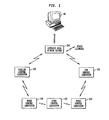
- Fig. 1 shows a block diagram of an exemplary building control system in accordance with the present invention.
- the building control system 100 includes a supervisory computer 102, a wireless area network server 104, a chiller controller subsystem 106, a fan controller subsystem 108, and room controller subsystems 110, 112 and 114.
- the building control system 100 includes only the few above-mentioned elements for clarity of exposition of the principles of the invention. Typical building control systems will include many more space control subsystems, as well as many more chiller, fan, heater, and other building HVAC subsystems. Those of ordinary skill in the art may readily incorporate the methods and features of the invention described herein into building control systems of larger scale.
- the building control system 100 employs a first wireless communication scheme to effect communications between the supervisory computer 102, the chiller controller subsystem 106, the fan controller subsystem 108, and the room controller subsystems 110, 112 and 114.
- a wireless communication scheme identifies the specific protocols and RF frequency plan employed in wireless communications between sets of wireless devices.
- the first wireless communication scheme is implemented as a wireless area network.
- a wireless area network server 104 coupled to the supervisory computer 102 employs a packet-hopping wireless protocol to effect communication by and among the various subsystems of the building control system 100.
- U.S. Patent No. 5,737,318 describes a wireless packet hopping network that is suitable for HVAC/building control systems of substantial size.
- the chiller controller subsystem 106 is a subsystem that is operable to control the operation of a chiller plant, not shown, within the building.
- Chiller plants as is known in art, are systems that are capable of chilling air that may then be ventilated throughout all or part of the building to enable air conditioning.
- Various operations of chiller plants depend upon a number of input values, as is known in the art. Some of the input values may be generated within the chiller controller subsystem 106, and other input values are externally generated. For example, operation of the chiller plant may be adjusted based on various air flow and/or temperature values generated throughout the building. The operation of the chiller plant may also be affected by set point values generated by the supervisory computer 102. The externally-generated values are communicated to the chiller controller subsystem 106 using the wireless area network.
- the fan controller subsystem 108 is a subsystem that is operable to control the operation of a ventilation fan, not shown, within the building.
- a ventilation fan as is known in art, is a prime mover of air flow throughout the ventilation system of the building. This primary air flow power may be used to refresh the air within the facility, and may be used to distribute chilled air from the chiller plant. As with the chiller plant, ventilation fans and their implementation within building control systems are well known in the art. Also, the fan controller subsystem 108 is similarly configured to receive input values from other subsystems (or the supervisory computer 102) over the wireless area network.
- the room controllers 110, 112 and 114 are local controller subsystems that operate to control an environmental aspect of a location or "space" within the building. While such locations may be referred to herein as "rooms” for convenience, it will be appreciated that such locations may further be defined zones within larger open or semi-open spaces of a building.
- the environmental aspect(s) that are controllable by the space control subsystems 110, 112 and 114 typically include temperature, and may include air quality, lighting and other building system processes.
- each of the space control subsystems 110, 112 and 114 has multiple elements that communicate with each other using a second wireless communication scheme.
- the second communication scheme employ a short-range or local RF communication sheme such as Bluetooth.
- Fig. 2 shows a schematic block diagram of an exemplary room control system that may be used as the space control subsystems 110.
- the space control subsystem 110 includes a hub module 202; first and second sensor modules 204 and 06 respectively, and an actuator module 208. It will be appreciated that a particular room controller subsystem 200 may contain more or less sensor modules or actuator modules.
- the space control subsystem 110 is operable to assist in regulating the temperature within a room or space pursuant to a set point value.
- the space control subsystem 110 is further operable to obtain data regarding the general environment of the room for use, display or recording by a remote device, not shown in Fig. 2 , of the building control system. (E.g., supervisory computer 102 of Fig. 1 ).
- the first sensor module 204 represents a temperature sensor module and is preferably embodied as a wireless integrated network sensor that incorporates microelectromechanical system technology ("MEMS").
- MEMS microelectromechanical system technology
- the first sensor module 204 includes a MEMS local RF communication circuit 210, a microcontroller 212, a programmable non-volative memory 214, a signal processing circuit 216, and one or more MEMS sensor devices 218.
- the first sensor module 204 also contains a power supply/source 220.
- the power supply/source 220 is a battery, for example, a coin cell battery.
- MEMS circuits suitable for implementing the first sensor module 204 are described in the ESSCIRC98 Presentation "Wireless Integrated Network Sensors (WINS)", which is published on-line at www.janet.ucla.edu/WINS/archives, (hereinafter referred to as the "WINS Presentation").
- WINS Wireless Integrated Network Sensors
- the MEMS sensor device(s) 218 include at least one MEMS sensor, which may suitably be a temperature sensor, flow sensor, pressure sensor, and/or gas-specific sensor. MEMS devices capable of obtaining temperature, flow, pressure and gas content readings have been developed and are known in the art. In a preferred embodiment, several sensors are incorporated into a single device as a sensor suite 218. Upon installation, the sensor module 204 may be programmed to enable the particular sensing capability. By incorporating different, selectable sensor capabilities, a single sensor module design may be manufactured for use in a large majority of HVAC sensing applications. In the embodiment of Fig. 2 , the sensor module 204 is configured to enable its temperature sensing function.
- the signal processing circuit 216 includes the circuitry that interfaces with the sensor, converts analog sensor signals to digital signals, and provides the digital signals to the microcontroller 212. Examples of low power, micro-electronic A/D converters and sensor interface circuitry are shown in the WINS Presentation.
- the programmable non-volatile memory 214 which may be embodied as a flash programmable EEPROM, stores configuration information for the sensor module 204.
- programmable non-volatile memory 214 preferably includes system identification information, which is used to associate the information generated by the sensor module 204 with its physical and/or logical location in the building control system.
- the programmable non-volatile memory 214 may contain an "address" or "ID" of the sensor module 204 that is appended to any communications generated by the sensor module 110.
- the memory 214 further includes set-up configuration information related to the type of sensor being used. For example, if the sensor device(s) 218 are implemented as a suite of sensor devices, the memory 214 includes the information that identifies which sensor functionality to enable. (See Figs. 3 and 4 , discussed further below).
- the memory 214 may further include calibration information regarding the sensor, and system RF communication parameters (i.e. the second RF communication scheme) employed by the microcontroller 212 and/or RF communication circuit 210 to transmit information to other devices.
- the microcontroller 212 is a processing circuit operable to control the general operation of the sensor module 204. In general, however, the microcontroller 212 receives digital sensor information from the signal processing circuit 216 and provides the information to the local RF communication circuit 210 for transmission to a local device, for example, the hub module 202. The microcontroller 212 may cause the transmission of sensor data from time-to-time as dictated by an internal counter or clock, or in response to a request received from the hub module 202.
- the microcontroller 212 is further operable to receive configuration information via the RF communication circuit 210, store configuration information in the memory 214, and perform operations in accordance with such configuration information.
- the configuration information may defme which of multiple possible sensor functionalities is to be provided by the sensor module 204.
- the microcontroller 212 employs such information to cause the appropriate sensor device or devices from the sensor device suite 218 to be operably connected to the signal processing circuit such that sensed signals from the appropriate sensor device are digitized and provided to the microcontroller 212.
- the microcontroller 212 may also use the configuration information to format outgoing messages and/or control operation of the RF communication circuit 210.
- the MEMS local RF communication circuit 210 may suitably include a Bluetooth RF modem, or some other type of short range (about 30 - 100 feet) RF communication modem.
- a MEMS-based RF communication circuit allows for reduced power consumption, thereby enabling the potential use of a true wireless, battery operated sensor module 204.
- a suitable exemplary MEMS-based RF communication circuit is discussed in the WINS Presentation.
- the sensor module 204 is configured to operate as a temperature sensor.
- the memory 214 stores information identifying that the sensor module 204 is to operate as a temperature sensor. Such information may be programmed into the memory 214 via a wireless programmer.
- the module 204 may be programmed upon shipment from the factory, or upon installation into the building control system.
- the microcontroller 212 responsive to the configuration information, causes the signal processing circuit 216 to process signals only from the temperature sensor, ignoring output from other sensors of the sensor suite 218.
- the sensor suite 218 may be replaced by a single sensor.
- additional advantages may be realized through the use of a configurable sensor module capable of performing any of a plurality of sensor functions. As discussed further above, these advantages include the reduction of the number of sensor module designs.
- the sensor module 206 is configured to operate as a flow sensor in the embodiment described herein.
- the sensor module 206 may suitably have the same physical construction as the sensor module 204.
- the sensor module 206 includes a local RF communication circuit 230, a microcontroller 232, a programmable non-volatile memory 234, a signal processing circuit 236, a sensor suite 238, and a power supply/source 240.
- the memory 234 of the sensor module 206 contains configuration information identifying that the sensor module 206 is to function as a flow sensor.
- the actuator module 208 is a device that is operable to cause movement or actuation of a physical device that has the ability to change a parameter of the building environment.
- the actuator module 208 in the embodiment described herein is operable to control the position of a ventilation damper, thereby controlling the flow of heated or chilled air into the room.
- the actuator module 208 is also preferably embodied as a wireless integrated network device that incorporates microelectromechanical system ("MEMS") devices.
- MEMS microelectromechanical system
- the actuator module 208 includes a MEMS local RF communication circuit 250, a microcontroller 252, a programmable non-volatile memory 254, and a signal processing circuit 256.
- the actuator module 208 also contains a power supply/source 260.
- the power supply/source 260 is a battery, for example, a coin cell battery.
- AC power is necessary for the actuator device (i.e. the damper actuator), which may be solenoid or value, then AC power is readily available for the power supply/source 260. As a consequence, the use of battery power is not necessarily advantageous.
- the actuator 262 itself may suitably be a solenoid, stepper motor, or other electrically controllable device that drives a mechanical HVAC element.
- the actuator 262 is a stepper motor for controlling the position of a vent damper.
- the MEMS local RF communication circuit 250 may suitably be of similar construction and operation as the MEMS local RF communication circuit 210. Indeed, even if the MEMS local RF communication circuit 250 differs from the RF communication circuit 210, it nevertheless should employ the same communication scheme.
- the microcontroller 252 is configured to receive control data messages via the RF communication circuit 250.
- the control data messages are generated and transmitted by the hub module 202.
- the control data messages typically include a control output value intended to control the operation of the actuator 262.
- the microcontroller 252 is operable to obtain the control output value from a received message and provide the control output value to the signal processing circuit 256.
- the signal processing circuit 256 is a circuit that is configured to generate an analog control signal from the digital control output value. In other words, the signal processing circuit 256 operates as an analog driver circuit.
- the signal processing circuit 256 includes an output 258 for providing the analog control signal to the actuator 262.
- the non-volatile memory 254 is a memory that contains configuration and/or calibration information related to the implementation of the actuator 262.
- the memory 254 may suitably contain sufficient information to effect mapping between the control variables used by the hub module 202 and the control signals expected by the actuator 262.
- the control variables used by the hub module 202 may be digital values representative of a desired damper position charge.
- the actuator 262, however, may expect an analog voltage that represents an amount to rotate a stepper motor.
- the memory 254 includes information used to map the digital values to the expected analog voltages.
- the hub module 202 in the exemplary embodiment described herein performs the function of the loop controller (e/g a PID controller) for the space control subsystem 110.
- the hub module 202 obtains process variable values (i.e . sensor information) from either or both of the sensor modules 204 and 206 and generates control output values.
- the hub module 202 provides the control output values to the actuator module 208.
- the hub module 202 also communicates with external elements of the building control system, for example, the supervisory computer, fan or chiller control subsystems, and other room controller subsystems.
- the hub module 202 further includes sensor functionality.
- sensor functionality In general, it is often advantageous to combine the hub controller core functionality with a sensor function to reduce the overall number of devices in the system.
- some room control subsystems could include hub module 202 with an integrated temperature sensor and one or more actuator modules. Separate sensor modules such as the sensor module 204 would not be necessary.
- the hub module 202 includes a network interface 270, a room control processor 272, a non-volatile memory 274, a signal processing circuit 276, a MEMS sensor suite 278 and a MEMS local RF communication circuit 280.
- the network interface 270 is a communication circuit that effectuates communication to one or more components of the building control system that are not a part of the space control subsystem 110. Referring to Fig. 1 , the network interface 270 is the device that allows the space control subsystem 110 to communicate with the supervisory computer 102, the fan controller subsystem 106, the chiller controller subsystem 108 and/or the other room controller subsystems.
- the network interface 270 is preferably an RF modem configured to communicate using the wireless area network communication scheme.
- the network interface 270 employs a packet-hopping protocol to reduce the overall transmission power required. In packet-hopping, each message may be transmitted through multiple intermediate network interfaces before it reaches its destination.
- the space control subsystem 110 sends a message to the fan control subsystem 106
- the network interface of the space control subsystem 110 provides the message to the physically closest subsystem.
- the network interface of the space control subsystem 110 provides the message to the network interface of the space control subsystem 112.
- the network interface of the space control subsystem 112 reads the destination address of the message and determines that the message is not intended to be received at the space control subsystem 112. As a consequence, the network interface of the space control subsystem 112 passes the message along to the network interface of the next closes subsystem, which is the space control subsystem 114. The network interface of the space control subsystem 114 similarly passes the message onto the fan control subsystem 116. The network interface of the fan control subsystem 116, however, recognizes from the destination address in the message that it is the intended recipient. The network interface of the fan control subsystem 116 thus receives the message and processes it.
- the network interface 270 is preferably operable to communicate using a short range wireless protocol.
- the network interface 270 is further operable to, either alone or in conjunction with the control processor 272, interpret messages in wireless communications received from external devices and determine whether the messages should be retransmitted to another external device, or processed internally to the module 202.
- the network interface 270 may receive a message intended for another subsystem. In such a case, the network interface 270 retransmits the message to another device.
- the network interface 270 includes a temperature set point for the space control subsystem 110 of Fig. 2 , then the network interface 270 passes the information to the room control processor 272.
- the hub module 202 may optionally include sensor capability.
- the MEMS sensor suite 278 may suitably include a plurality of MEMS sensors, for example, a temperature sensor, flow sensor, pressure sensor, and/or gas-specific sensor.
- the hub module 202 may be programmed to enable the particular desired sensing capability. In this manner, a single hub module design may be manufactured to for use in a variety of HVAC sensing applications, each hub module 202 thereafter being configured to its particular use. (See e.g. Figs. 3 and 4 ). However, it may be sufficient to provide hub control modules having only temperature sensing capability because rooms that employ an HVAC controller also typically require a temperature sensor. Thus, a temperature sensor on the hub module will nearly always fill a sensing need when the hub module is employed.
- the signal processing circuit 276 includes the circuitry that interfaces with the sensor suite 278, converts analog sensor signals to digital signals, and provides the digital signals to the room control processor 272. As discussed above, examples of low power, micro-electronic A/D converters and sensor interface circuitry are shown in the WINS Presentation.
- the programmable non-volatile memory 274 which may be embodied as a flash programmable EEPROM, stores configuration information for the hub module 274.
- programmable non-volatile memory 274 preferably includes system identification information, which is used to associate the information generated by the sensor module 274 with its physical and/or logical location in the building control system.
- the memory 274 further includes set-up configuration information related to the type of sensor being used.
- the memory 274 may further include calibration information regarding the sensor, and system RF communication parameters employed by the control processor 272, the network interface 270 and/or the local RF communication circuit 280.
- the MEMS local RF communication circuit 280 may suitably include a Bluetooth RF modem, or some other type of short range (about 30 - 100 feet) RF communication modem.
- the MEMS local RF communication circuit 280 is operable to communicate using the same RF communication scheme as the MEMS local RF communication circuits 210, 230 and 250.
- the use of a MEMS-based RF communication circuit allows for reduced power consumption, thereby enabling the potential use of a true wireless, battery operated hub module 202.
- the control processor 272 is a processing circuit operable to control the general operation of the hub module 274.
- the control processor 272 implements a control transfer function to generate control output values that are provided to the actuator module 208 in the space control subsystem 110.
- the control processor 272 obtains sensor information from its own sensor suite 278 and/or from sensor modules 204 and 206.
- the control processor 272 also receives a set point value, for example, from the supervisory computer 102 via the network interface 270.
- the control processor 272 then generates the control output value based on the set point value and one or more sensor values.
- the control processor 272 may suitably implement a proportional-integral-differential (PID) control algorithm to generate the control output values.
- PID proportional-integral-differential
- FIG. 3 shows an exemplary set of operations of the hub module 202
- Fig. 4 shows an exemplary set of operations of the sensor module 204
- Fig. 5 shows an exemplary set of operations of the actuator module 208.
- FIG. 3 the operations shown therein will be described with contemporaneous reference to Fig. 2 .
- the operations of Fig. 3 are performed by the room control processor 272, which generally controls the operation of the hub module 202.
- Steps 302, 304. and 306 all represent operations in which the room control processor 272 receives input values from various sources. The order in which those steps are performed is not of critical importance.
- the processor 272 receives a flow value from the sensor module 206, which in the exemplary embodiment described herein has been configured as a flow sensor module.
- the processor 272 causes the local RF communication circuit 280 to be configured to receive a transmitted message from the local RF communication circuit 230 of the sensor module 206.
- the local RF communication circuit 280 and/or the processor 278 verify the source and intended destination of the message. If the message is legitimately intended for the hub module 202, then the processor 278 parses the sensor value from the message for subsequent use.
- the processor 272 receives temperature measurement values from the sensor module 204 as well as its internal temperature sensor device 278. In many cases, only a single temperature sensor value is necessary, in which case the hub module 202 need not include the temperature sensor 278, or, alternatively, the sensor module 204 would not be necessary. In the exemplary embodiment described herein, however, it will be assumed that the processor 272 receives temperature values from both the temperature sensor device 278 and the sensor module 204. To receive a temperature value from the sensor module 204, the processor 272 and local RF communication circuit 280 operate in the same manner as that described above in connection with receiving flow sensor values from the sensor module 206. To receive a temperature value from the sensor 278, the processor 272 receives digital sensor information from the signal processing circuit 276.
- the processor 272 obtains a set point value through the network interface 270.
- the set point temperature for the room in which the control subsystem 110 is disposed is provided from a device external to the control subsystem 110.
- the supervisory computer 102 of Fig. 1 may provide the temperature set points for all of the space control subsystems 110,112 and 114 in the building control system 100.
- the set point may be derived from a manually-adjustable mechanism directly connected to the hub module 202.
- the network interface 270 monitors transmissions in the WAN on which the various subsystems communicate. If a message including a set point intended for the space control subsystem 110 is received by the network interface 270, then that message will be provided to the processor 272. In such a case, the processor 272 parses out the set point information for subsequent use, such as use in the execution of step 308, discussed below.
- the processor 272 In step 308, the processor 272 generates a control output value based on the most recently received set point value and temperature sensor values. To this end, the processor 272 may suitably employ a PID controller algorithm to generate the control output value.
- the control output value is representative of a desired change in a vent damper position. For example, if chilled air is provided through the vent, and the sensor temperature value exceeds the set point temperature value, then the control output value identifies that the vent damper must be opened further. Further opening the vent damper allows more chilled air to enter the room, thereby reducing the temperature.
- a PID control algorithm that is capable of generating a vent damper position based on a difference between temperature sensor values and a set point temperature value would be known to one of ordinary skill in the art.
- control system elements such as temperature sensors, set point temperatures, and vent dampers are given by way of illustrative example.
- the use of control systems and subsystems with reduced wiring as generally described herein may be implemented in control systems implementing a variety of sensor devices and actuators or other controlled devices.
- the processor 272 does not require an update in each of steps 302, 304 and 306 prior to performing step 308. Any update received in any of those steps can justify a recalculation of the control output value. Moreover, the processor 272 may recalculate the control output value on a scheduled basis, without regard as to which input values have changed.
- step 310 the processor 272 causes the generated control output value to be communicated to the actuator module 208.
- the processor 272 and the local RF communication circuit 280 cooperate to generate a local RF signal that contains information representative of the control output value.
- the processor 272 may suitably add a destination address representative of the actuator module 208 to enable the actuator module 208 to identify the message.
- the flow sensor value received from the flow sensor module 206 is not used in the PID control calculation performed by the processor 272. That value is obtained so that it may be used by other subsystems or by the supervisory computer 102. Indeed, multiple sensor values are typically communicated to external subsystems.
- the processor 272 causes the network interface 270 to transmit received sensor values to devices external to the room control subsystem 110.
- the processor 272 may cause temperature and flow sensor values to be transmitted to the supervisory computer 102.
- the supervisory computer 102 may then use the information to monitor the operation of the building control system.
- temperature and/or flow sensor values from various space control subsystems may be employed by the fan control subsystem 108 to adjust operation of one or more ventilation fans, or by the chiller control subsystem 106 to adjust operation of the chiller plant.
- the processor 272 must from time to time cause sensor values generated within the space control subsystem 110 to be communicated to external devices through the network interface 270.
- the room control processor 272 repeats steps 302-312 on a continuous basis. As discussed above, the steps 302-312 need not be performed in any particular order. New sensor and/or set point values may be received periodically either on a schedule, or in response to requests generated by the processor 272.
- Fig. 4 shows an exemplary set of operations performed by the sensor module 204 in generating and transmitting temperature sensor values to the hub module 202 in accordance with step 302 of Fig. 3 .
- the sensor module 206 may suitably perform a similar set of operations to generate and transmit flow sensor values to the hub module 202 in accordance with step 304 of Fig. 3 .
- step 402 the microcontroller 212 determines whether it is time to transmit an updated temperature value to the hub module 202.
- the determination of when to transmit temperature values may be driven by a clock internal to the sensor module 204, or in response to a request or query received from the hub module 202, or both. In either event, if it is not time to transmit an update, the microcontroller 212 repeats step 402.
- step 404 the microcontroller 212 obtains a digital value representative of a measured temperature from the signal processing circuit 216. To this end, the microcontroller 212. preferably "wakes up" from a power saving mode. The microcontroller 212 preferably also causes bias power to be connected to power consuming circuits in the signal processing circuit 216, such as the A/D converter. In this manner, power may be conserved by only activating power consuming circuits when a temperature sensor value is specifically required. Otherwise, the power consuming devices remain deactivated.
- step 404 the microcontroller 212 proceeds to step 406.
- step 406 the microcontroller 212 converts the sensed digital temperature value into the format expected by the room control processor 272 of the hub module 202.
- the microcontroller 212 further prepares the message for transmission by the local RF communication circuit 210.
- the microcontroller 212 in step 408 causes the local RF communication circuit 210 to transmit the message.
- the message is thereafter received by the hub module 202 (see step 304 of Fig. 3 ). Thereafter, the microcontroller 212 may return to step 402 to determine the next time an update is required.
- Fig. 5 shows an exemplary set of operations that may be performed by the microcontroller 252 of the actuator module 208.
- one purpose of the space control subsystem 110 is to control the physical operation of a device to help regulate a process variable, in this case, the room temperature.
- the actuator module 208 thus operates to carry out the actions determined to be necessary in accordance with the control algorithm implemented by the room process controller 272.
- step 502 a message which may include the control output value is received from the hub module 202.
- the RF communication circuit 250 receives the message and provides the message to the microcontroller 252.
- the microcontroller 252 determines whether the received message is intended for receipt by the actuator module 208. If not, then the microcontroller 252 returns to step 502 to await another incoming message.
- step 504 the microcontroller 252 determines in step 504 that the received message is intended for the actuator module 208, then the microcontroller 252 proceeds to step 506.
- step 506 the microcontroller 252 parses the message to obtain the actuator control output value, and converts that value into a value that will cause the actuator to perform the requested adjustment. For example, if the received control output value identifies that the ventilator damper should be opened another 10%, then the microcontroller 252 would generate a digital output value that, after being converted to analog in the signal processing circuit 256, will cause the actuator 258 to open the ventilator damper another 10%.
- step 508 the microcontroller 252 actually provides the digital output value to the signal processing circuit 256.
- the signal processing circuit 256 then converts the value to the corresponding analog voltage expected by the actuator device 258. Thereafter, the microcontroller 252 returns to step 502 to await the next message received from the hub module 202.
- space control subsystem 110 is merely an exemplary illustration of the principles of the invention.
- the principles of the invention may readily be applied to control subsystems having more or less sensors or actuators, as well as other elements.
- Fig. 6 shows an exemplary embodiment of the space control subsystem 114 of the building control system 100 of Fig. 1 .
- the space control subsystem 114 of Fig. 6 is used in a space or room 610 that includes two fume hoods 612 and 614.
- a fume hood as is known in the art, is a fume collection device disposed over an enclosed surface.
- the fume hoods 612 and 614 allow for experiments or processes that involve noxious gasses fumes by conducting those gasses away from the experimental area.
- the room 610 is coupled in an air communication relationship with an air flow supply duct 618 in which are disposed a supply damper 620 and a radiator or heating coil device 616.
- the room 610 is also coupled to communicate air to an exhaust duct 622 through a main exhaust damper 624.
- Fume hood dampers 626 and 628 communicate air/gas within the fume hoods 612 and 614, respectively, to the exhaust duct 622.
- the space control subsystem 114 is designed to both regulate the temperature within the room 610 as well as ensure that the fume hoods 612 and 614 achieve their purpose in conducting away gasses.
- the space control subsystem 114 controls the operation of the supply damper 620 and the heating coil 616 to control the supply of heated or cooled air into the room 610.
- the space control subsystem 114 control the main exhaust damper 624 in a coordinated fashion with the supply damper 620 to ensure sufficient fresh air and proper atmospheric pressure is maintained within the room 610.
- the space control subsystem 114 controls the operation of the fume hood dampers 626 and 628 to conduct gasses away when their presence is detected.
- the supply damper 620 and/or the main exhaust damper 624 is also controlled in a coordinated manner to ensure that the required air flow to conduct gasses away is available through the appropriate fume hood damper 626 or 628.
- the space control subsystem 114 includes a control module 630, a supply flow module 632, a main exhaust module 634, a first fume hood exhaust module 636, a second fume hood exhaust module 638, a first fume hood sensor module 640, and a second fume hood sensor module 642.
- the control module 620 generally operates to effectuate communication between the space control subsystem 114 and the other subsystems of the building control system 100 (see Fig. 1 ).
- the control module 620 further includes a temperature sensor.
- the supply flow module 632 controls the supply damper 620 to regulate the supply of air flow into the space 610, and further controls the supply of heat (or cool) water to the heating coil element 616 disposed in the path of the air flow supply.
- the main exhaust module 634 controls the main exhaust damper 624 to regulate the flow of air out of the space 610, such that in general the atmospheric pressure within the room is controlled by the cooperative efforts of the supply flow module 622 and the main exhaust module 624.
- the first fume hood exhaust module 636 controls the damper 626 to control the exhaust or venting of fumes or gas from within or in the vicinity of the fume hood 612.
- the second fume hood exhaust module 638 controls the damper 628 to control the exhaust or venting of fumes or gas from within or in the vicinity of the fume hood 614.
- the first fume hood sensor module 640 is operable to obtain measurements indicative of the concentration of a gas within the fume hood 612, while the second fume hood sensor module 642 is operable to obtain measurements indicative of the concentration of a gas with the fume hood 614.
- Figs. 7a-b, 8a-c, 9a-b, 10a-b and 11a-b describe the structure and operation of the various modules 630 through 642 of the space control subsystem 114 in order to carry out the above described control operations.
- Figs. 7a and 7b describe the structure and operation of the control module 630
- Figs. 8a, 8b and 8c describe the structure and operation of the supply module 632
- Figs. 9a and 9b describe the structure and operation of the main exhaust module 634
- Figs. 10a and 10b describe the structure and operation of the first fume hood sensor module 640 (which is also applicable to the second fume hood sensor module 642)
- Figs. 11a and 11b describe the structure and operation of the first fume hood exhaust module 636 (which is also applicable to the second fume hood exhaust module 638).
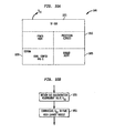
- Figs. 12a and 12b show an exemplary embodiment of a flexible, MEMS-based module design that is particularly useful in building control, automation, comfort, security and/or safety systems.
- the module 1200 is implemented as a single, self powered, standalone device in which most of the active components are integrated onto one or two semiconductor substrates:
- the module 1200 in the embodiment described herein includes a top semiconductor layer 1202, a lithium ion battery layer 1204 and a bottom semiconductor layer 1206.
- the various functions of the module 1200 discussed below in connection with Fig. 12b , are incorporated into the top and bottom semiconductor layers 1202 and 1206.
- the lithium ion battery layer 1204 provides a source of electrical power to the top and bottom semiconductor layers 1202 and 1206.
- the lithium ion battery layer 1204 is preferably disposed between the top and bottom semiconductor layers 1202 and 1206 to provide an advantageous, space-efficient layout.
- Various interconnects may be provided between the two semiconductor layers 1202 and 1206 around the lithium ion battery layer 1204 as need.
- one of the two layers may be dedicated completely to a light-powered recharging circuit for the lithium ion battery layer 1204.
- all of the elements of the module 1200 may be implemented onto a single semiconductor substrate such as the layer 1202.
- Fig. 12b shows a block diagram representation of the module circuits 1250 that are implemented into the semiconductor layers 1202 and 1206 of the module 1200.
- the module circuit 1250 include a sensor suite 1252, an EEPROM 1254, a processing circuit 1256, a power management circuit 1258 and an RF communication circuit 1260.
- the RF communication circuit 1260 is a MEMS based communication circuit such as that described above in connection with Fig. 2 .
- the RF communication circuit 1260 is preferably configured to communicate using at least one local RF communication format, such as Bluetooth.
- the power management circuit 1258 that preferably operates to recharge the lithium ion battery layer 1204 of Fig. 6 , and may include semiconductor devices that convert light or RF energy into electrical energy that may be used to trickle charge the lithium ion battery.
- the sensor suite 1252 is collection of MEMS sensors incorporated into a single substrate.
- MEMS sensor technologies For example, Hydrometrics offers for sale a MEMS sensor device that includes both temperature and humidity sensing functions. MEMS based light, gas content, temperature, flow, smoke and other sensing devices are known. Such devices are in the embodiment described herein implemented onto a single substrate 1202 or 1206, or pair of substrates 1202 and 1206.
- the processing circuit 1256 incorporates a microprocessor or microcontroller, as well as microelectronics A/D circuits for connecting to the MEMS sensor devices of the sensor suite 1252. As such, the processing circuit 1256 performs the operations described above in connection with the signal processing circuit 216 and controller 212 of the sensor module 204 of Fig. 2 .
- the EEPROM 1254 (which may be another type of non-volatile, chip-based memory such as ferro-electric or ferro-magnetic RAM) is a non-volatile memory that stores the configuration information for the module 1200.
- the EEPROM 1254 may store ID information used to identify the module 1200 to the system in which it is connected.
- the EEPROM 1254 also stores information related to the function in which the module 1200 will be used.
- the EEPROM 1254 may store information identifying that the module 1200 should enable its temperature sensing function as opposed to any of its other possible sensing functions.
- the configuration information in the EEPROM 1254 may simply identify the intended functionality of the module 1200, which would then cause the processing circuit 1256 to execute portions of program code stored in ROM (not shown) to carry out that identified functionality.
- the EEPROM 1254 may be replaced by a set of DIP switches that may be manually manipulated to set the configuration of the module 1200. In either case, such embodiments would require that most of the program code for a variety of different sensor functions be stored in ROM, only a portion of which would be used once the configuration information is received.
- most or all of the code unique to the selected function of the module is downloaded into the EEPROM 1254 during configuration of the device.
- the module 1200 is to operate as a temperature sensor module, then all appropriate code for a temperature sensor module is downloaded to the EEPROM 1254, as is identification information and calibration information. This method provide maximum flexibility because a single module 1200 may be programmed to do many custom tailored tasks, in addition to performing sensor functions.
- the configuration information is downloaded to the EEPROM 1254 from an external device, for example, a portable programming device.
- a portable programming device provides programming instructions via RF signals to the RF communication circuit 1260.
- the processing circuit 1256 obtains the programming instructions from the RF communication circuit 1260 and stores the instructions into the EEPROM 1254. It will be appreciated that other techniques for providing configuration information to the EEPROM 1254 may be used.
- the above described module 1200 may readily be configured as any one of a large plurality of sensor types or even other types of building automation system components. As a consequence, large amounts of the devices may be fabricated, thereby reducing the per-unit tooling and design costs associated with ordinary building automation sensors. In addition, the highly integrated nature of the devices reduces shipping and storage costs, as well as reduces power consumption. It will be noted that the design of the module 1200 may be used as the sensor modules 204, 206 in the exemplary space control subsystem 200 of Fig. 2 , and may also be used as the hub module 202. In such a case, the network interface 270 of the hub module 202 may be configured to operate via the RF communication circuit 1260 of the module 1200 of Figs. 12a and 12b .
- modules 630, 632, 634, 636, 638, 640 and 642 all employ the design and construction of the module 1200 of Figs. 12a and 12b .
- other assemblies of those circuits may be employed and achieve at least some of the benefits of the invention.
- Fig. 7a shows an exemplary block diagram of the control module 630
- Fig. 7b shows an exemplary flow diagram of the operations performed by the control processor of the control module 630.
- the control module 630 cooperates with the supply module 632 and main exhaust module 634 to control the temperature in the room 610.
- the control module 630 also facilitates communication of information, if necessary, between any of the modules 630-642 and elements of other subsystems of the building control system 100 (see Fig. 1 ).
- control module 630 has a general construction substantially similar to the module 1200 of Figs. 12a and 12b .
- the control module 630 includes an RF communication circuit 705, a power management circuit 710, a processing circuit 715, an EEPROM 720, and a sensor suite 725.
- Each of the elements of the control module operates generally as described above in connection with Figs. 12a and 12b .
- the control module 630 includes a temperature sensing functionality.
- the EEPROM 720 includes configuration information identifying that processing circuit 715 should obtain and process temperature measurement information from the MEMS sensor suit 725.
- the EEPROM 720 further includes sufficient program instructions or code to carry out the operations illustrated in Fig. 7b and described below.
- the RF communication circuit 705 is preferably configured to communicate with the other elements of the subsystem 114 as well as in the local area network between subsystems. To this end, the RF communication circuit 705 may be able to communicate using the two different communication schemes described above in connection with Figs. 1 and 2 . In particular, one scheme would be used for communications within the subsystem 114 and the other scheme would be used to communicate to other subsystems and devices external to the subsystem 114. Alternatively, the RF communication circuit 705 may instead communicate using only a single RF communication scheme. External communications would be carried out through a separate network interface device, not shown, that is itself capable of communicating using the two different communication schemes.
- the processing circuit 715 receives from time to time a room temperature set point value W T .
- the RF communication circuit 705 receives the information within communication signals from one or more devices external to the subsystem 114 such as, for example, the supervisory computer 102 of Fig. 1 .
- the RF communication circuit 705 then provides the information to the processing circuit 715.
- all or part of the temperature set point may be provided via a manual control device disposed within the room 610.
- step 750 the processing circuit 715 receives the set points W GJFL and W G2FL from, respectively the fume hood exhaust modules 636 and 638.
- the processing circuit 715 also receives the measured exhaust flow X FLO from the main exhaust module 634.
- the processing circuit 715 receives such information from transmitted RF signals from the modules 634, 636 and 638 via the RF communication circuit 705.
- the set points W G1FL and W G2FL represent the exhaust air flow through the exhaust dampers 626 and 628 from the fume hoods 612 and 614, respectively.
- the control module 630 uses the values W G1FL and W G2FL to adjust the supply flow to accommodate any additional outflow through the dampers 626 and 628. In particular, whenever it becomes necessary to vent fumes through the fume hood via either of the dampers 626 or 628, the supply flow at the supply damper 620 is increased to provide additional air pressure to force air flow through the dampers 626 and/or 628.
- the supply flow may remain constant and the main exhaust damper 624 may be further closed or restricted to force exhaust air flow through the fume hood exhaust dampers 626 and/or 628.
- a combination of partially closing off the main exhaust damper 624 and further opening the supply damper 620 may be used.
- the supply damper 620 is adjusted to compensate for additional (or decreased) flow cause by opening (or closing) the fume hood exhaust dampers 626 and/or 628. For this reason, the processing circuit 715 receives W G1FL and W G2FL in step 750, as well as W T .
- step 755 the processing circuit 715 also receives from time to time a room temperature measurement value X T . To this end, the processing circuit 715 obtains an analog temperature measurement value from the temperature sensor element within the MEMS sensor suite 725 and converts the analog temperature measurement value to a representative digital value thereof X T .
- step 760 the processing circuit 715 generates a temperature control output value Y T .
- the value Y T actually represents an interim value in the system indicative of how the system must change to achieve the temperature set point W T .
- Y T is a function of W T and X T .
- Y T may suitably be set to the error signal W T - X T .
- step 765 the processing circuit 715 calculates the main exhaust set point W FLO based on the current exhaust X FLO and the temperature control output Y T .
- the function that determines W FLO carries out the operations set forth below.
- the flow of cool air from the supply duct 618 should be decreased.
- the main exhaust flow set point W FLO is adjusted downward, if possible.
- the reduction in the exhaust flow and corresponding reduction in supply flow reduces the flow of cool air into the room 610 and should result in an increase in the temperature.
- the main exhaust flow is already minimized, in other words, the main exhaust damper 624 is substantially closed, then the main exhaust flow set point W FLO cannot be adjusted further downward.
- the determination as to whether the main exhaust damper 624 is substantially closed is based on the exhaust flow X FLO value.
- step 765 may readily be carried out by any number of suitable function definitions that determine W FLO based on Y T and X FLO .
- step 770 the processing circuit 715 calculates the supply flow set point W FL based on the exhaust flow set point W FLO and the two fume hood exhaust flow set points, W G1FL and W G2FL .
- the processing circuit 715 calculates the supply flow set point W FL based on the exhaust flow set point W FLO and the two fume hood exhaust flow set points, W G1FL and W G2FL .
- the supply flow increases or decreases responsive to the change of either of the fume hood exhausts. For example, if the fume hood 612 must be vented, then the first fume hood exhaust flow set point W G1FL is increased (see Figs. 10 and 11 ) and the supply flow set point W FL is increased accordingly. As a consequence, the subsystem 114 automatically increases air flow into the room 610 to supply the needed additional pressure to vent fumes through the fume hood exhaust dampers 626 and/or 628.
- step 770 the supply flow set point W FL is set responsive to based on the exhaust flow set points W FLO , W G1FL , and W G2FL
- the processing circuit 715 determines the heating coil set point W HC based on the temperature control value Y T and the supply flow set point W FL.
- the temperature in the room remains low (i.e. Y T is positive) for a long time, it is indicative that the attempts to raise the temperature through control of the air flow (in steps 765 and 770) were not successful.
- the heating coil 616 should be turned on.
- the heating coil set point W HC is determined based on the value of Y T over time.
- the amount of heating provided by the convection air flow over the heating coil 616 depends in part on the air flow rate past the heating coil 616. Accordingly, the heating coil set point W HC is also preferably determined as a function of the supply flow set point W FL .
- the above steps 765 and 770 regulate the supply flow of cooler air into the room 610 to control the temperature.
- the heating coil 616 is used to help regulate temperature in step 775.
- the supply flow of cooler air in some cases cannot be reduced (to raise room temperature) because of the need for air flow to vent gasses out of the fume hoods 612 and/or 614.
- the heating coil 616 is actuated and the supply flow actually provides warm air that raises the room temperature.
- the processing circuit 715 causes the RF communication circuit 705 to communicate the room flow set point W FL and the heating coil set point W HC to the supply flow module 632, and to communicate the exhaust flow set point W FLO to the main exhaust module 634.
- Operation of the supply flow module 632 is discussed below in connection with Figs. 8a, 8b and 8c .
- Operation of the main exhaust module 634 is discussed below in connection with Figs. 9a and 9b .
- the processing circuit 715 thereafter periodically receives updates of X FLO , W G1FL , W G2FL , and/or W T via the RF communication circuit 705, and updates of the measured temperature X T from the sensor suite 725. While these updates are typically interrupt-based, such that reception of one of the values causes recalculation of one or more of the values W FLO , W FL or W HC , another suitable update and recalculation scheme would involve periodically requesting updates to any or all of W G1FL , W G2FL , W T and/or X T . In either event, upon receiving one or more updates, the processing circuit 715 preferably repeats of steps 760, 765, 770, 775 and 780.
- steps 750 through 780 need not be executed in the order illustrated in Fig. 7b , nor must both steps 750 and 755 be executed prior to each subsequent execution of steps 760 through 780. However, over the course of operation, steps 750 through 780 will be executed repeatedly.
- control module 630 may determine the set point for the supply flow damper 620, the exhaust flow damper 624 and the heater coil 616 in order to control the room temperature. It will be appreciated that the control module 730 may readily be adapted to other methods to control the temperature. The control module 630 further adjusts the supply flow as necessary to compensate for the need for additional air flow to vent fumes out of this exhaust dampers 626 and/or 628.
- control module 730 does not directly cause actuators of the heating coil or air flow equipment to act. Instead, the control module 730 merely obtains the set points, W FLO , W FL and W HC , for such equipment.
- the actuators for the supply damper 620 and heater coil 616 are controlled by the supply flow module 632.
- the actuator for the main exhaust damper 624 is controlled by the main exhaust module 634.
- the supply flow module 632 has a general construction substantially similar to the module 550 of Figs. 12a and 12b .
- the supply flow module 632 includes an RF communication circuit 805, a power management circuit 810, an processing circuit 815, an EEPROM 820, and a sensor suite 825.
- Each of the elements of the control module operates generally as described above in connection with Figs. 12a and 12b .
- the control module 830 includes a flow sensing functionality, and is further configured to generate actuator output signals.
- the actuator output signals may suitably be provided as analog output pins 815a, 815b on the processing circuit 815.
- the actuator output signals are analog outputs that control the operation of actuators for the heating coil 616 and the damper 620. To this end, the analog output pins 815a and 815b are connected to external actuators 817 and 818.
- the EEPROM 820 includes configuration information identifying that the processing circuit 815 should obtain an air flow measurement information from the MEMS sensor suit 825.
- the EEPROM 820 further includes sufficient program instructions or code to carry out the operations illustrated in Figs. 8b and 8c and described below.
- the RF communication circuit 805 is preferably configured to communicate with the other elements of the subsystem 114. As discussed above, the RF communication circuit 805 may suitably be configured to use Bluetooth or another local RF communication protocol.
- Figs. 8b and 8c show an overview of two separate functions of the processing circuit 815.
- Fig. 8b shows the function related to regulation of the supply air flow in the room 610 while Fig. 8c shows the function related to control of the heater coil 616.
- step 850 the processing circuit 815 receives from time to time (via the RF communication circuit 805) the set points W FL and W HC from the control module 630.
- the use of the heating coil set point W HC is discussed further below in connection with step 880 of Fig. 8c .
- the processing circuit 815 also receives a supply air flow measurement value X FL . To this end, the processing circuit 815 obtains an analog flow measurement value from the flow sensor element within the MEMS sensor suite 825 and converts the analog flow measurement value to a digital value representative thereof, X FL .
- step 860 the processing circuit 815 calculates a supply flow damper control output Y FL based on the measured flow X FL and the set point value W FL .
- the processing circuit 815 may use an ordinary PID algorithm.
- step 865 the processing circuitI 815 provides an actuator output signal corresponding to Y FL to its output 815a, which in turn provides to the actuator 817 that causes mechanical adjustment of the supply flow damper 620.
- the processing circuit 815 thereafter periodically receives updates of its inputs and recalculates the output value of step 860. Steps 850, 855, 860 and 865 need not be executed in the order illustrated in Fig. 8b .
- Fig. 8c shows a flow diagram of the steps of the processing circuit 815 in controlling the actuator 818 of the heater coil 616.
- the processing circuit 815 receives the heating coil set point W HC through the RF communication circuit 805.
- the processing circuit 815 thereafter in step 885 sets the actuator control output Y HC to value that is the functional equivalent of W HC and provides Y HC to the output 815b.
- the heating coil actuator control output Y HC then propagates to the actuator 818.
- the actuator 818 thereafter affects the operation of the heating coil 616 in a manner responsive to the control output Y HC in a manner that would be known to those of ordinary skill in the art.
- the processing circuit 815 may thereafter receive periodic updates, via request or otherwise, and then repeat steps 880 and 885. Steps 880 and 885 may suitably executed independently of steps of the steps of Fig. 8b .
- the above operations of the processing circuit 815 cause the supply flow module 632 to control both the heating coil 616 and the supply flow damper 620 to regulate the temperature and fresh air supply into the room 610.
- the processing circuit 815 uses local RF communications to obtain the necessary set points and other data to carry out the operations.
- the processing circuit 815 communicates exhaust flow information to the main exhaust module 624.
- Figs. 9a and 9b show the structure and operation of the main exhaust module 634.
- the main exhaust control module 634 effectively controls the main exhaust damper 624 to help regulate the removal of "spent" air that is being replace with "fresh” air through the supply conduit 618.
- fresh air is preferably supplied to the room 610 even in the absence of noxious fumes or gas, particularly to provide cooling air to maintain a steady temperature into the room.
- the main exhaust module 634 has a general construction substantially similar to the module 120 of Figs. 12a and 12b .
- the main exhaust module 634 includes an RF communication circuit 905, a power management circuit 910, an processing circuit 915, an EEPROM 920, and a sensor suite 925.
- Each of the elements of the main exhaust module 634 operates generally as described above in connection with Figs. 12a and 12b .
- the main exhaust module 634 includes a flow sensing functionality, and is further configured to generate an actuator output signal.
- the actuator output signal may suitably be provided as analog output pin 915a on the processing circuit 915.
- the actuator output signal is an analog output that controls the operation of actuator for the damper 624.
- the analog output pin 815a is connected to an external actuator 917, which in turn controls the position of the damper 624.
- the EEPROM 920 includes configuration information identifying that the processing circuit 915 should obtain an air flow measurement information from the MEMS sensor suite 925.
- the EEPROM 920 further includes sufficient program instructions or code to carry out the operations illustrated in Fig. 9b and described below.
- the RF communication circuit 905 is preferably configured to communicate with the other elements of the subsystem 114. As discussed above, the RF communication circuit 905 may suitably be configured to use Bluetooth or another local RF communication protocol.
- Fig. 9b shows an overview of the functions of the processing circuit 915.
- the processing circuit 915 receives from time to time (via the RF communication circuit 905) the main exhaust set point W FLO , which is provided by the control module 630, as discussed above.
- step 955 the processing circuit 915 receives a main exhaust flow measurement X FLO .
- the processing circuit 915 obtains an analog flow measurement value from the flow sensor element within the MEMS sensor suite 925 and converts the analog flow measurement value to a digital value representative thereof X FLO .
- step 960 the processing circuit 915 calculates a main exhaust damper control output Y FLO based on the measured flow X FLO and the set point value W FLO .
- the processing circuit 915 may use an ordinary PID algorithm.
- step 965 the processing circuit 915 provides an actuator output signal corresponding to Y FLO to its output 915a, which in turn provides the actuator output signal to the actuator 917.
- the actuator 917 causes mechanical adjustment of the main exhaust damper 624 responsive to the actuator output signal.
- step 970 the processing circuit 915 causes the RF communication circuit 970 to communicate the measured flow value X FLO to the control module 630.
- the processing circuit 915 thereafter periodically receives updates of its inputs and recalculates the actuator output signal. In other words, steps 950-970 are periodically repeated.
- the above operations of the processing circuit 915 operate to control the main exhaust of "spent" air to the room based on the set point W FLO generated by the control module 632. (See Fig. 8b ). Alternative calculations of the exhaust flow set point W FLO may be made. As discussed further above, in alternative embodiments, the main exhaust flow may be adjusted to redirect air flow through the fume hood exhaust dampers 626 and/or 628. Regardless, one feature of this embodiment of the invention is that balance between the supply flow and the main exhaust flow is adjusted in response to a need to vent air or gas through the fume hood exhausts.
- Figs. 10a and 10b show the structure and operation of the first fume hood sensor module 640.
- the first fume hood sensor module 640 effectively measures the concentration of one or more select noxious gasses within the first fume hood 612. It will be appreciated that the second fume hood sensor module 642 has a substantially similar construction and operates in a substantially similar way.
- the first fume hood sensor module 640 has a general construction substantially similar to the module 1200 of Figs. 12a and 12b .
- the first fume hood sensor module 640 includes an RF communication circuit 1005, a power management circuit 1010, an processing circuit 1015, an EEPROM 1020, and a sensor suite 1025.
- Each of the elements of the first fume hood sensor module 640 operates generally as described above in connection with Figs. 12a and 12b .
- the first fume hood sensor module 640 includes a gas concentration sensing functionality.
- the gas may be any of a number of noxious gasses.
- various MEMS sensors devices are known that detect the concentration of various gasses.
- the sensor suite 1025 may suitable include a plurality of gas-specific sensors.
- the EEPROM 1020 includes configuration information identifying that the processing circuit 1015 should obtain gas concentration measurement information for one or more gasses from the MEMS sensor suite 1025. It is noted that the gas sensing functionality should correspond to the types of noxious gas or gasses expected to be generated within the fume hood 612. With the configurable EEPROM 1020, the module 640 may be reconfigured if the type of noxious gas generated within the fume hood 612 changes.
- the first fume hood sensor module 640 may include a MEMs-based gas chromatography element in the sensor suite 1025. Such an element can provide gas chromatographic information to the processing circuit 1015. The processing circuit 1015 may then analyze the information for specific gas content. The EEPROM 1020 would provide conriguration information as to which gasses to monitor.
- a suitable MEMs-based gas chromatography device is the "Lab on a Chip" available from Argon National Laboratories. Others are known in the art.
- the configuration information of the EEPROM 1020 may identify a template defining breathable air, for example, having specific ranges of oxygen, nitrogen and carbon dioxide.
- the processing circuit 1015 uses this template to determine whether the oxygen, nitrogen and/or other breathable air gasses are within predefined limits. If not, then X G1 would be given a value that indicates the need for additional venting.
- the EEPROM 1020 further includes sufficient program instructions or code to carry out the operations illustrated in Fig. 10b and described below.
- the RF communication circuit 1005 is preferably configured to communicate with the other elements of the subsystem 114. As discussed above, the RF communication circuit 1005 may suitably be configured to use Bluetooth or another local RF communication protocol.
- the processing circuit 1015 obtains a gas concentration measurement value X G1 .
- the processing circuit 1015 obtains an analog gas concentration measurement value from the gas concentration sensor element within the MEMS sensor suite 1025 and converts the analog flow measurement value to a digital value representative thereof, X G1 .
- step 1055 the processing circuit 1015 provides the gas concentration measurement value X G1 to the first fume hood exhaust module 636 via the RF communication circuit 1005.
- steps 1050 and 1055 may be repeated for each gas.
- the processing circuit 1015 thereafter periodically receives updates of its inputs and recalculates the actuator output signal. In other words, steps 1050 and 1055 are periodically repeated.
- Figs. 11a and 11b show the structure and operation of the first fume hood exhaust module 636.
- the first fume hood exhaust module 636 effectively controls the first fume hood exhaust damper 626 to help vent noxious gasses present within or in the vicinity of the fume hood 612 out of the room 610.
- the need for venting is based on the concentration measurement value X G1 generated by the first fume hood sensor module 640, and a gas concentration set point W G1 .
- the second fume hood exhaust module 638 has a similar construction and operates in substantially the same manner as the first fume hood exhaust module 636.
- the first fume hood exhaust module 636 has a general construction that is substantially similar to the module 1200 of Figs. 12a and 12b .
- the first fume hood exhaust module 636 includes an RF communication circuit 1105, a power management circuit 1110, an processing circuit 1115, an EEPROM 1120, and a sensor suite 1125.
- Each of the elements of the first fume hood exhaust module 636 operates generally as described above in connection with Figs. 12a and 12b .
- the first fume hood exhaust module 636 includes a flow sensing functionality, and is further configured to generate an actuator output signal.
- the actuator output signal may suitably be provided on analog output pin 1115a of the processing circuit 1115.
- the actuator output signal is an analog output that controls the operation of the actuator for the damper 626.
- the analog output pin 1115 a is connected to an external actuator 1117, which in turn controls the position of the damper 626.
- the EEPROM 1120 includes configuration information identifying that the processing circuit 1115 should obtain an air flow measurement information from the MEMS sensor suite 1125.
- the EEPROM 1120 also includes information identifying the tolerable limits for concentration of the gas, or in other words, the gas concentration set point W G1 for the gas x being measured in the first fume hood 612.
- the EEPROM 720 further includes sufficient program instructions or code to carry out the operations illustrated in Fig. 11b and described below.
- the RF communication circuit 1105 is preferably configured to communicate with the other elements of the subsystem 114 using a local RF communication protocol.
- the processing circuit 1115 receives from time to time (via the RF communication circuit 1105) the gas concentration measurement value X G1 , which is provided by the first fume hood sensor module 640, as discussed above.
- step 1155 the processing circuit 1115 calculates a first gas concentration control output Y G1 based on the measured gas concentration value X G1 and the gas concentration set point W G1 .
- the processing circuit 1115 may use an ordinary PID algorithm, the configuration of which would be known to those of ordinary skill in the art.
- the processing circuit 1115 receives a first fume hood exhaust flow measurement X G1FL . To this end, the processing circuit 1115 obtains an analog flow measurement value from the flow sensor element within the MEMS sensor suite 1125 and converts the analog flow measurement value to a digital value representative thereof, X G1FL .
- step 1170 the processing circuit 1115 calculates a first fume hood exhaust damper control output Y G1FL based on the measured flow X G1FL and the set point value W G1FL .
- the processing circuit 1115 may use an ordinary PID algorithm to perform the calculation.
- step 1175 the processing circuit 1115 provides an actuator output signal corresponding to Y G1FL to its output 1115a, which in turn provides to the actuator 1117 that causes mechanical adjustment of the first fume hood exhaust damper 626.
- the processing circuit 1115 thereafter periodically receives updates of its inputs and recalculates the actuator output signal. In other words, steps 1150-1175, although not necessarily in strict order.
- the processing circuit 1115 also communicates the set point W G1FL to the control module 630.
- the above operations of the processing circuit 1115 operate to control the venting of gas-laden air through control of the damper 626.
- the processing circuit 1115 controls the venting based on the measured gas concentration X G1 received periodically from the first fume hood sensor module 640 and the desired gas concentration set point W G1 stored in the EEPROM 1120. It is noted that the value of W G1 may be programmed into the EEPROM 1120 upon configuration of the module 636, or may be received from supervisory devices external to the subsystem 114 via the control module 630. It will also be noted, the control calculation of step 1155 may be carried out in the first fume hood sensor module 640.
- One of the advantages of incorporating wireless MEMS modules in a building subsystem or system that includes fume hoods is the reduced wiring requirements over normal fume hood systems. Moreover, by detecting the relative presence of noxious gasses within the fume hood, the fume hood is only vented when noxious gasses are present, or in other words, only as needed. The arrangement thus potentially conserves energy by ventilating only to the extent necessary. It is noted that the fume hood sensor module 640 and/or the fume hood exhaust module 636 may be programmed to detect an alarm condition and provide a wireless (or wire output pin) signal to a visible and/or audible alarm device, not shown.
- subsystems incorporating features from either or both of subsystems 110 and 114 may be used in building control systems that are not completely wireless.
- the space control subsystems 110 of Fig. 2 may readily be modified for use in a conventional wired building control system.
Landscapes
- Engineering & Computer Science (AREA)
- Business, Economics & Management (AREA)
- Accounting & Taxation (AREA)
- Finance (AREA)
- Physics & Mathematics (AREA)
- General Physics & Mathematics (AREA)
- Technology Law (AREA)
- Development Economics (AREA)
- Economics (AREA)
- Marketing (AREA)
- Strategic Management (AREA)
- General Business, Economics & Management (AREA)
- Theoretical Computer Science (AREA)
- General Engineering & Computer Science (AREA)
- Automation & Control Theory (AREA)
- Arrangements For Transmission Of Measured Signals (AREA)
- Management, Administration, Business Operations System, And Electronic Commerce (AREA)
- Air Conditioning Control Device (AREA)
- Installation Of Indoor Wiring (AREA)
- Fire Alarms (AREA)
- Respiratory Apparatuses And Protective Means (AREA)
- Ventilation (AREA)
- Treating Waste Gases (AREA)
- Elevator Control (AREA)
Claims (21)
- Procédé de commande d'un aspect environnemental d'une zone dans un bâtiment, comprenant les stades dans lesquels :a ) on produit une valeur de consigne se rapportant à l'aspect environnemental par un ordinateur ( 102 ) de supervision ;b ) on communique la valeur de consigne à un module ( 202 ) de concentrateur en utilisant un premier schéma de communication sans fil ;c ) on obtient une valeur de processus à partir d'un dispositif ( 218 ;238 ) de capteur MEMS ;d ) on communique sans fil de l'information et sur la base de la valeur du processus au module ( 202 ) de concentrateur en utilisant un deuxième schéma de communication qui est différent du premier schéma de communication sans fil ; ete ) on commande un actionneur ( 262 ) en réaction à l'information.
- Procédé suivant la revendication 1, dans lequel la valeur de processus est représentative d'une concentration d'une substance gazeuse.
- Procédé suivant une revendication précédente, dans lequel le dispositif de capteur MEMS est disposé dans une hotte ( 612 ; 614 ) à fumée.
- Procédé suivant une revendication précédente, dans lequel le module ( 202 ) de concentrateur comprend un dispositif de commande et le stade e ) comprend en outre l'emploi du dispositif de commande pour commander l'actionneur en réaction à l'information.
- Procédé suivant une revendication précédente, dans lequel l'information comprend une sortie de commande déterminée sur la base au moins en partie de la valeur de consigne et de la valeur de processus.
- Procédé suivant la revendication 3, dans lequel dans le stade e ) on utilise le deuxième schéma de communication et l'actionneur commandé est un actionneur de registre de ventilation.
- Procédé suivant la revendication 6, dans lequel en outref) on effectue des communications sans fil vers un troisième dispositif en utilisant le deuxième schéma de communication, la communication sans fil contenant une deuxième information identifiant une caractéristique d'écoulement d'air au voisinage du registre de ventilation,g) on commande le deuxième actionneur fixé à un deuxième registre sur la base de la deuxième information.
- Dispositif ( 110, 600 ) de commande d'un système ( 100 ) de commande de bâtiment pour effectuer un procédé suivant l'une des revendications 1 à 7,
le dispositif ( 110 ) de commande comprenant un module ( 202 ) de concentrateur et au minimum un module ( 204;206 ) de capteur ayant un dispositif ( 218 ; 238 ) de capteur à technologie de système micro-électromécanique ( MEMS ) et un circuit ( 210 ; 230 ) local de communication RF,
le module ( 202 ) de concentrateur comprenant une interface ( 270 ) de réseau, un processeur ( 272 ) de commande et un circuit ( 280 ) de communication RF pour une communication sans fil avec le module ( 204 ) de capteur,
l'interface ( 270 ) de réseau pouvant fonctionner pour une communication avec un autre dispositif ( 106 ;108 ;112 ;214 ) de commande du système ( 100 ) de commande du bâtiment en utilisant un premier schéma de communication sans fil,
le module ( 204 ;206 ) de capteur pouvant fonctionner pour produire une valeur de processus et pour transmettre des données sans fil au module ( 202 ) de concentrateur en utilisant un deuxième schéma de communication qui est différent du premier schéma de communication sans fil. - Dispositif ( 110 ;600 ) de commande suivant la revendication 8, comprenant en outre un module ( 208 ; 632 ) d'actionneur couplé fonctionnellement à un élément ( 620 ) d'actionnement et ayant un circuit ( 250 ) local de communication RF pour communiquer avec le module ( 202 ; 630 ) de concentrateur en utilisant le deuxième schéma de communication.
- Dispositif ( 110 ;600 ) de commande suivant l'une des revendications 8 à 9, dans lequel le module ( 202 ) de concentrateur comprend en outre un dispositif ( 278 ) de capteurs MEMS.
- Dispositif ( 110 ; 600 ) de commande suivant la revendication 10, dans lequel le circuit ( 280 ) de communication RF du module ( 202 ) de concentrateur est un circuit local de communication RF MEMS.
- Dispositif ( 110 ;600 ) de commande suivant l'une quelconque des revendications 8 à 11, dans lequel le dispositif ( 218 ;238 ) de capteur MEMS est une suite de capteur incorporant plusieurs capteurs MEMS dont l'aptitude particulière de détection peut être programmée après montage.
- Dispositif ( 110 ;600 ) de commande suivant l'une quelconque des revendications 8 à 12, dans lequel un signal de commande du module ( 208 ;632 ) d'actionneur est fourni par le module ( 208 ; 632 ) de concentrateur en utilisant une communication sans fil.
- Dispositif ( 110 ; 600 ) de commande suivant l'une quelconque des revendications 8 à 13, dans lequel le module ( 204 ; 206 ) de capteur comprend un dispositif ( 212 ;216 ;232 ; 236 ) de traitement incorporé dans le même substrat que le capteur ( 218 ; 238 ) MEMS.
- Dispositif ( 110 ;600 ) de commande suivant l'une quelconque des revendications 8 à 14, comprenant en outre un dispositif de commande pouvant fonctionner pour obtenir la valeur de processus produite par le module ( 204 ;206 ) de capteur et pouvant fonctionner pour fournir une sortie de commande.
- Dispositif ( 110 ; 600 ) de commande suivant l'une quelconque des revendications 8 à 15, dans lequel le module ( 204 ;206 ) de capteur est disposé dans une hotte ( 612 ; 614 ) à fumée.
- Dispositif ( 110 ;600 ) de commande suivant l'une des revendications 8 à 16, dans lequel le module ( 204 ; 206 ) de capteur comprend un capteur d'écoulement d'air pouvant fonctionner pour produire une valeur de processus d'écoulement d'air et dans lequel le dispositif de commande peut fonctionner en outre pour fournir la sortie de commande sur la base en partie de la valeur de processus d'écoulement d'air.
- Dispositif ( 110 ;600 ) de commande suivant l'une des revendications 8 à 17, dans lequel le module ( 204 ; 206 ) de capteur peut fonctionner en outre pour fournir de l'information à un autre module ( 208 ) en utilisant le deuxième schéma de communication.
- Dispositif ( 110 ;600 ) de commande suivant l'une des revendications 8 à 18, dans lequel le module ( 202 ) de concentrateur comprend une suite de capteur incorporant plusieurs capteurs MEMS dont l'aptitude particulière à la détection peut être programmée après montage.
- Dispositif ( 110 ;600 ) de commande suivant l'une des revendications 8 à 19, dans lequel le premier schéma de communication comprend un protocole sans fil à bond de paquets.
- Dispositif ( 110 ;600 ) de commande suivant l'une des revendications 8 à 20, dans lequel le deuxième schéma de communication est un schéma de communication RF à courte distance.
Applications Claiming Priority (3)
| Application Number | Priority Date | Filing Date | Title |
|---|---|---|---|
| US35245202P | 2002-01-28 | 2002-01-28 | |
| US352452P | 2002-01-28 | ||
| PCT/US2003/002559 WO2003065136A1 (fr) | 2002-01-28 | 2003-01-28 | Systeme de commande d'immeuble et son systeme de hotte de captation des fumees a besoins en cablages reduits |
Publications (2)
| Publication Number | Publication Date |
|---|---|
| EP1470456A1 EP1470456A1 (fr) | 2004-10-27 |
| EP1470456B1 true EP1470456B1 (fr) | 2009-12-30 |
Family
ID=27663097
Family Applications (2)
| Application Number | Title | Priority Date | Filing Date |
|---|---|---|---|
| EP03735054A Expired - Lifetime EP1470457B1 (fr) | 2002-01-28 | 2003-01-28 | Systeme de gestion de batiments requerant peu de fils, et appareil associe |
| EP03707570A Expired - Lifetime EP1470456B1 (fr) | 2002-01-28 | 2003-01-28 | Systeme de commande d'immeuble et son systeme de hotte de captation des fumees a besoins en cablages reduits |
Family Applications Before (1)
| Application Number | Title | Priority Date | Filing Date |
|---|---|---|---|
| EP03735054A Expired - Lifetime EP1470457B1 (fr) | 2002-01-28 | 2003-01-28 | Systeme de gestion de batiments requerant peu de fils, et appareil associe |
Country Status (6)
| Country | Link |
|---|---|
| US (5) | US8131399B2 (fr) |
| EP (2) | EP1470457B1 (fr) |
| AT (2) | ATE530961T1 (fr) |
| AU (1) | AU2003210706A1 (fr) |
| DE (1) | DE60330750D1 (fr) |
| WO (2) | WO2003065136A1 (fr) |
Cited By (1)
| Publication number | Priority date | Publication date | Assignee | Title |
|---|---|---|---|---|
| US9854653B1 (en) | 2017-01-31 | 2017-12-26 | Crestron Electronics Inc. | Scalable building control system, method, and apparatus |
Families Citing this family (65)
| Publication number | Priority date | Publication date | Assignee | Title |
|---|---|---|---|---|
| US8352400B2 (en) | 1991-12-23 | 2013-01-08 | Hoffberg Steven M | Adaptive pattern recognition based controller apparatus and method and human-factored interface therefore |
| US10361802B1 (en) | 1999-02-01 | 2019-07-23 | Blanding Hovenweep, Llc | Adaptive pattern recognition based control system and method |
| US8364136B2 (en) | 1999-02-01 | 2013-01-29 | Steven M Hoffberg | Mobile system, a method of operating mobile system and a non-transitory computer readable medium for a programmable control of a mobile system |
| US7904187B2 (en) | 1999-02-01 | 2011-03-08 | Hoffberg Steven M | Internet appliance system and method |
| US8140658B1 (en) | 1999-10-06 | 2012-03-20 | Borgia/Cummins, Llc | Apparatus for internetworked wireless integrated network sensors (WINS) |
| US6660948B2 (en) | 2001-02-28 | 2003-12-09 | Vip Investments Ltd. | Switch matrix |
| US7305467B2 (en) * | 2002-01-02 | 2007-12-04 | Borgia/Cummins, Llc | Autonomous tracking wireless imaging sensor network including an articulating sensor and automatically organizing network nodes |
| EP1470457B1 (fr) * | 2002-01-28 | 2011-10-26 | Siemens Industry, Inc. | Systeme de gestion de batiments requerant peu de fils, et appareil associe |
| JP2004013450A (ja) * | 2002-06-06 | 2004-01-15 | Hitachi Ltd | 配電盤開閉装置と操作監視制御システム |
| US20040144849A1 (en) * | 2003-01-28 | 2004-07-29 | Osman Ahmed | Building control system using integrated MEMS devices |
| US7394451B1 (en) | 2003-09-03 | 2008-07-01 | Vantage Controls, Inc. | Backlit display with motion sensor |
| US7307542B1 (en) | 2003-09-03 | 2007-12-11 | Vantage Controls, Inc. | System and method for commissioning addressable lighting systems |
| US7755506B1 (en) | 2003-09-03 | 2010-07-13 | Legrand Home Systems, Inc. | Automation and theater control system |
| US7664573B2 (en) * | 2003-09-26 | 2010-02-16 | Siemens Industry, Inc. | Integrated building environment data system |
| US7610910B2 (en) * | 2004-03-25 | 2009-11-03 | Siemens Building Technologies, Inc. | Method and apparatus for controlling building component characteristics |
| US7665670B2 (en) * | 2004-03-25 | 2010-02-23 | Siemens Industry, Inc. | Method and apparatus for an integrated distributed MEMS based control system |
| US7860495B2 (en) * | 2004-08-09 | 2010-12-28 | Siemens Industry Inc. | Wireless building control architecture |
| US7469547B2 (en) * | 2004-09-09 | 2008-12-30 | Siemens Building Technologies, Inc. | Arrangement for detecting the position of a damper blade using a wireless communication sensor |
| US7667588B2 (en) * | 2004-09-27 | 2010-02-23 | Siemens Industry, Inc. | Cage telemetry module and system |
| US20060071785A1 (en) * | 2004-09-27 | 2006-04-06 | Osman Ahmed | Cage telemetry system using intermediate transponders |
| KR20060059621A (ko) * | 2004-11-29 | 2006-06-02 | 엘지전자 주식회사 | 공기 조화기를 시운전하는 장치 |
| US20060280202A1 (en) * | 2005-06-13 | 2006-12-14 | Analog Devices, Inc. | MEMS sensor with configuration module |
| US7684835B1 (en) * | 2005-07-12 | 2010-03-23 | Marvell Interntional Ltd. | Wake on wireless LAN schemes |
| US20070021140A1 (en) * | 2005-07-22 | 2007-01-25 | Keyes Marion A Iv | Wireless power transmission systems and methods |
| EP1932065B1 (fr) * | 2005-08-30 | 2015-08-12 | Siemens Industry, Inc. | Dispositif de microsystemes a la maitrise du confort |
| US7780092B2 (en) * | 2005-08-30 | 2010-08-24 | Siemens Industry Inc. | Application of microsystems for real time IEQ control |
| DE602006012507D1 (de) * | 2005-09-06 | 2010-04-08 | Siemens Industry Inc | Anwendung von mikrosystemen für ein gebäudesystem mit einer system-wissensdatenbank |
| US7778262B2 (en) | 2005-09-07 | 2010-08-17 | Vantage Controls, Inc. | Radio frequency multiple protocol bridge |
| US7412899B2 (en) * | 2005-09-16 | 2008-08-19 | International Electronic Machines Corporation | MEMS-based monitoring |
| JP5363110B2 (ja) * | 2005-11-16 | 2013-12-11 | コーニンクレッカ フィリップス エヌ ヴェ | ユニバーサルrfワイヤレスセンサインターフェース |
| US7535186B2 (en) * | 2006-02-23 | 2009-05-19 | Regal-Beloit Corporation | Methods and systems for controlling operation of electronicallly commutated motors |
| ITMI20060346A1 (it) * | 2006-02-27 | 2007-08-28 | Intea Engineering Tecnologie E ... | Rete di ventilconvettori senza fili |
| US7317970B2 (en) * | 2006-03-02 | 2008-01-08 | Siemens Building Technologies, Inc. | Remote sensing for building automation |
| US8023440B2 (en) * | 2006-08-30 | 2011-09-20 | Siemens Industry, Inc. | Binding wireless devices in a building automation system |
| JP2008232531A (ja) * | 2007-03-20 | 2008-10-02 | Toshiba Corp | リモート性能監視装置及びリモート性能監視方法 |
| EP1995653A1 (fr) * | 2007-05-22 | 2008-11-26 | Abb Research Ltd. | Système de contrôle d'un processus automatisé |
| US8160752B2 (en) | 2008-09-30 | 2012-04-17 | Zome Networks, Inc. | Managing energy usage |
| US8700924B2 (en) * | 2008-05-21 | 2014-04-15 | International Electronic Machines Corp. | Modular sensor node and communications system |
| US8346398B2 (en) * | 2008-08-08 | 2013-01-01 | Siemens Industry, Inc. | Data center thermal performance optimization using distributed cooling systems |
| US8322151B1 (en) * | 2008-08-13 | 2012-12-04 | Demand Side Environmental, LLC | Systems and methods for gathering data from and diagnosing the status of an air conditioner |
| KR20110082129A (ko) | 2008-09-03 | 2011-07-18 | 지멘스 인더스트리, 인크. | 수동 및 능동 무선 빌딩 관리 시스템 및 방법 |
| WO2010120771A1 (fr) * | 2009-04-15 | 2010-10-21 | DiMi, Inc. | Système et procédé de commande et de surveillance de bâtiments à distance |
| NO330068B1 (no) * | 2009-05-08 | 2011-02-14 | Function Innovation & Technology As | Anordning for a male verdier som pavirker brukerkomfort og/eller energiforbruk i en bygning |
| GB2475540A (en) * | 2009-11-23 | 2011-05-25 | Charles Hugh Carr Wyn-Davies | Energy management system |
| US20110203569A1 (en) * | 2010-02-23 | 2011-08-25 | John Robert Weimer | Boiler system stabilizing damper and flue control method |
| US20120072327A1 (en) * | 2010-06-18 | 2012-03-22 | Tilly Edward T | Automated trading system for routing and matching orders |
| US11144992B1 (en) * | 2010-09-15 | 2021-10-12 | Cfph, Llc | Computer systems for selective transmission |
| US9454160B2 (en) * | 2012-03-21 | 2016-09-27 | Kabushiki Kaisha Toshiba | Thermal recycling plant system, apparatus for controlling a thermal recycling plant and method of controlling a thermal recycling plant |
| US9605860B2 (en) * | 2012-11-02 | 2017-03-28 | Flextronics Ap, Llc | Energy saving-exhaust control and auto shut off system |
| US10529215B2 (en) * | 2012-11-16 | 2020-01-07 | Vapor Products Group, Llc | Remote environmental condition monitoring and reporting |
| US9396497B2 (en) * | 2012-12-19 | 2016-07-19 | Nasdaq Technology Ab | Computer-implemented system and method for clearing a derivative trade involving multiple trading exchanges |
| CA3012609A1 (fr) | 2013-06-24 | 2014-12-31 | Aequitas Innovations Inc. | Systeme et procede d'echange automatise d'interets financiers |
| JP5669902B1 (ja) * | 2013-08-30 | 2015-02-18 | 三菱電機株式会社 | 空調機制御システム、センサ機器制御方法及びプログラム |
| DK2858318T3 (en) | 2013-09-09 | 2018-02-12 | Nex Services North America Llc Corp Trust Center | Process and apparatus for order entry in an electronic trading system |
| CN106105169B (zh) * | 2013-12-17 | 2020-03-31 | 贝利莫控股公司 | 移动通信装置和用于管理多个致动器的操作的方法 |
| WO2016057737A1 (fr) | 2014-10-10 | 2016-04-14 | Carrier Corporation | Système hvac comportant un étalonnage de réseau de capteurs actifs |
| US20160162990A1 (en) * | 2014-12-05 | 2016-06-09 | Chicago Mercantile Exchange Inc. | Enriched market data generation and reporting |
| CN104880981A (zh) * | 2015-04-30 | 2015-09-02 | 江苏海大印染机械有限公司 | 一种具有温湿监控功能的定型机 |
| US10395302B2 (en) * | 2015-07-02 | 2019-08-27 | Nasdaq, Inc. | Matching techniques for data transaction requests with private attributes |
| US10127615B1 (en) * | 2016-06-14 | 2018-11-13 | Chicago Stock Exchange, Inc. | System and method for delaying an executable instruction that would otherwise be executable immediately upon arrival at an executing system |
| US20180219695A1 (en) * | 2017-01-30 | 2018-08-02 | Brightswitch, Inc. | System and method for distributed home automation control |
| USD833402S1 (en) | 2017-01-30 | 2018-11-13 | Brightswitch, Inc. | Home automation control device |
| US10684037B2 (en) | 2017-10-04 | 2020-06-16 | Trane International Inc. | Thermostat and method for controlling an HVAC system with remote temperature sensor and onboard temperature sensor |
| JP2020030476A (ja) * | 2018-08-20 | 2020-02-27 | 富士ゼロックス株式会社 | 情報処理システム、自走式移動装置及びプログラム |
| US20240281902A1 (en) * | 2023-02-21 | 2024-08-22 | Abdulla Abdulsalam Z A Alyafei | Social media system for detecting, tracking, creating, and updating user activities and events |
Family Cites Families (56)
| Publication number | Priority date | Publication date | Assignee | Title |
|---|---|---|---|---|
| US115303A (en) | 1871-05-30 | Improvement in steam-traps | ||
| DD205017A5 (de) | 1981-06-16 | 1983-12-14 | Os Bad Roz Automat Proc Chemi | Verfahren zur steuerung von chemischen prozessen und eine anordnung zur durchfuehrung des verfahrens |
| US4528898A (en) * | 1984-03-05 | 1985-07-16 | Imec Corporation | Fume hood controller |
| US5115728A (en) * | 1990-09-28 | 1992-05-26 | Landis & Gyr Powers, Inc. | System for controlling the differential pressure of a room having laboratory fume hoods |
| US5090304A (en) * | 1990-09-28 | 1992-02-25 | Landis & Gyr Powers, Inc. | Apparatus for determining the position of a moveable structure along a track |
| US5092227B1 (en) * | 1990-09-28 | 1995-02-14 | Landis & Gyr Powers Inc | Apparatus for controlling the ventilation of laboratory fume hoods |
| US5090303A (en) * | 1990-09-28 | 1992-02-25 | Landis & Gyr Powers, Inc. | Laboratory fume hood control apparatus having improved safety considerations |
| US5297252A (en) * | 1991-05-07 | 1994-03-22 | Don Becker | Color graphics terminal for monitoring an alarm system |
| US5390206A (en) * | 1991-10-01 | 1995-02-14 | American Standard Inc. | Wireless communication system for air distribution system |
| US5361198A (en) | 1992-04-03 | 1994-11-01 | Combustion Engineering, Inc. | Compact work station control room |
| DE69428816T2 (de) | 1993-03-25 | 2002-04-11 | Nohmi Bosai Ltd., Tokio/Tokyo | Empfangsstation in Feueralarmsystem |
| US5568121A (en) * | 1993-05-27 | 1996-10-22 | Lamensdorf; David M. | Wireless system for sensing information at remote locations and communicating with a main monitoring center |
| US5439414A (en) * | 1993-07-26 | 1995-08-08 | Landis & Gyr Powers, Inc. | Networked fume hood monitoring system |
| US5631825A (en) * | 1993-09-29 | 1997-05-20 | Dow Benelux N.V. | Operator station for manufacturing process control system |
| US6169927B1 (en) | 1994-05-10 | 2001-01-02 | Siemens Aktiengesellschaft | Control system for an industrial installation |
| US5971597A (en) * | 1995-03-29 | 1999-10-26 | Hubbell Corporation | Multifunction sensor and network sensor system |
| US5808541A (en) * | 1995-04-04 | 1998-09-15 | Golden; Patrick E. | Hazard detection, warning, and response system |
| IL117424A (en) * | 1995-04-27 | 1999-09-22 | Optimark Tech Inc | Crossing network utilizing satisfaction density profile |
| US5562537A (en) * | 1995-05-11 | 1996-10-08 | Landis & Gyr Powers, Inc. | Networked fume hood monitoring system |
| US5853020A (en) * | 1995-06-23 | 1998-12-29 | Widner; Ronald D. | Miniature combination valve and pressure transducer and system |
| GB9517621D0 (en) * | 1995-08-29 | 1995-11-01 | Landis & Gyr Tech Innovat | Monitoring and/or control system |
| US5831848A (en) * | 1995-11-17 | 1998-11-03 | Phoenix Controls Corporation | Distributed environmental process control system |
| US5737318A (en) | 1995-12-27 | 1998-04-07 | Philips Electronics North America Corporation | Method for initializing a wireless, packet-hopping network |
| US6232968B1 (en) | 1998-03-31 | 2001-05-15 | International Business Machines Corporation | Data processor controlled display system with a plurality of switchable customized basic function interfaces for the control of varying types of operations |
| US6252689B1 (en) * | 1998-04-10 | 2001-06-26 | Aircuity, Inc. | Networked photonic signal distribution system |
| AU3772799A (en) | 1998-05-01 | 1999-11-23 | Abb Power T & D Company Inc. | Wireless area network communications module for utility meters |
| US6437692B1 (en) * | 1998-06-22 | 2002-08-20 | Statsignal Systems, Inc. | System and method for monitoring and controlling remote devices |
| US6252510B1 (en) * | 1998-10-14 | 2001-06-26 | Bud Dungan | Apparatus and method for wireless gas monitoring |
| US6137403A (en) * | 1998-12-10 | 2000-10-24 | Phoenix Controls Corporation | Sash sensor and method of sensing a sash using an array of multiplexed elements |
| US7562135B2 (en) * | 2000-05-23 | 2009-07-14 | Fisher-Rosemount Systems, Inc. | Enhanced fieldbus device alerts in a process control system |
| EP1169691A1 (fr) | 1999-03-12 | 2002-01-09 | Graviton, Inc. | Systemes et procedes de detection en reseau, et gestion distribuee des capteurs, des donnees et de la memoire |
| US6625500B1 (en) * | 1999-03-16 | 2003-09-23 | Chou H. Li | Self-optimizing method and machine |
| US6278982B1 (en) | 1999-04-21 | 2001-08-21 | Lava Trading Inc. | Securities trading system for consolidation of trading on multiple ECNS and electronic exchanges |
| US6613277B1 (en) * | 1999-06-18 | 2003-09-02 | Gerald C. Monagan | Air purifier |
| WO2001026328A2 (fr) * | 1999-10-06 | 2001-04-12 | Sensoria Corporation | Dispositif pour capteurs de reseau integre sans fil hybrides interconnectes en reseau |
| US6735630B1 (en) * | 1999-10-06 | 2004-05-11 | Sensoria Corporation | Method for collecting data using compact internetworked wireless integrated network sensors (WINS) |
| US6934862B2 (en) * | 2000-01-07 | 2005-08-23 | Robertshaw Controls Company | Appliance retrofit monitoring device with a memory storing an electronic signature |
| US20010048030A1 (en) * | 2000-01-07 | 2001-12-06 | Sharood John N. | Retrofit damper system |
| JP4129667B2 (ja) * | 2000-04-21 | 2008-08-06 | 富士フイルム株式会社 | 電池内蔵型基板 |
| AU2001263483A1 (en) | 2000-05-26 | 2001-12-11 | Royal Thoughts L.L.C. | Modular communication and control system and method |
| US20060097063A1 (en) * | 2000-07-07 | 2006-05-11 | Zvi Zeevi | Modular HVAC control system |
| US6829589B1 (en) | 2000-07-21 | 2004-12-07 | Stc, Llc | Method and apparatus for stock and index option price improvement, participation, and internalization |
| US6643555B1 (en) | 2000-10-10 | 2003-11-04 | Schneider Automation Inc. | Method and apparatus for generating an application for an automation control system |
| US6609967B2 (en) * | 2000-12-11 | 2003-08-26 | Phoenix Controls Corporation | Methods and apparatus for recirculating air in a controlled ventilated environment |
| US6993417B2 (en) * | 2001-09-10 | 2006-01-31 | Osann Jr Robert | System for energy sensing analysis and feedback |
| US20030151513A1 (en) * | 2002-01-10 | 2003-08-14 | Falk Herrmann | Self-organizing hierarchical wireless network for surveillance and control |
| EP1470457B1 (fr) | 2002-01-28 | 2011-10-26 | Siemens Industry, Inc. | Systeme de gestion de batiments requerant peu de fils, et appareil associe |
| JP4043879B2 (ja) * | 2002-07-24 | 2008-02-06 | 三菱電機株式会社 | プラント最適運転制御装置 |
| FI20021901A0 (fi) | 2002-10-24 | 2002-10-24 | Liqum Oy | Menetelmä prosessin valvomiseksi |
| US6823718B2 (en) * | 2002-10-28 | 2004-11-30 | Pti Technologies, Inc. | Single-body multiple sensing device |
| US7832465B2 (en) * | 2002-11-07 | 2010-11-16 | Shazhou Zou | Affordable and easy to install multi-zone HVAC system |
| US8264329B2 (en) * | 2003-01-10 | 2012-09-11 | Monismart Systems, Llc | Method and system for room activity communication |
| SG119301A1 (en) | 2004-07-09 | 2006-02-28 | Ebs Group Ltd | Automated trading systems |
| US7860495B2 (en) * | 2004-08-09 | 2010-12-28 | Siemens Industry Inc. | Wireless building control architecture |
| US20060184444A1 (en) | 2005-02-11 | 2006-08-17 | Mcconaughy Jon | Trading tool to enhance stock and commodity index execution |
| JP2007018490A (ja) | 2005-02-23 | 2007-01-25 | Sony Corp | 行動制御装置および行動制御方法、並びに、プログラム |
-
2003
- 2003-01-28 EP EP03735054A patent/EP1470457B1/fr not_active Expired - Lifetime
- 2003-01-28 EP EP03707570A patent/EP1470456B1/fr not_active Expired - Lifetime
- 2003-01-28 WO PCT/US2003/002559 patent/WO2003065136A1/fr not_active Ceased
- 2003-01-28 US US10/353,142 patent/US8131399B2/en active Active
- 2003-01-28 AT AT03735054T patent/ATE530961T1/de active
- 2003-01-28 WO PCT/US2003/002556 patent/WO2003064933A2/fr not_active Ceased
- 2003-01-28 AU AU2003210706A patent/AU2003210706A1/en not_active Abandoned
- 2003-01-28 AT AT03707570T patent/ATE453882T1/de not_active IP Right Cessation
- 2003-01-28 DE DE60330750T patent/DE60330750D1/de not_active Expired - Lifetime
- 2003-01-28 US US10/353,110 patent/US20040088082A1/en not_active Abandoned
-
2011
- 2011-09-09 US US13/229,054 patent/US8433644B2/en not_active Expired - Fee Related
-
2012
- 2012-02-03 US US13/366,095 patent/US8538589B2/en not_active Expired - Fee Related
-
2013
- 2013-03-15 US US13/842,355 patent/US9754322B1/en not_active Expired - Fee Related
Cited By (1)
| Publication number | Priority date | Publication date | Assignee | Title |
|---|---|---|---|---|
| US9854653B1 (en) | 2017-01-31 | 2017-12-26 | Crestron Electronics Inc. | Scalable building control system, method, and apparatus |
Also Published As
| Publication number | Publication date |
|---|---|
| EP1470456A1 (fr) | 2004-10-27 |
| AU2003210706A1 (en) | 2003-09-02 |
| US20120005066A1 (en) | 2012-01-05 |
| WO2003064933A2 (fr) | 2003-08-07 |
| EP1470457B1 (fr) | 2011-10-26 |
| DE60330750D1 (de) | 2010-02-11 |
| WO2003064933A3 (fr) | 2003-12-18 |
| US9754322B1 (en) | 2017-09-05 |
| US20120212352A1 (en) | 2012-08-23 |
| US8131399B2 (en) | 2012-03-06 |
| ATE453882T1 (de) | 2010-01-15 |
| WO2003065136A1 (fr) | 2003-08-07 |
| US8538589B2 (en) | 2013-09-17 |
| US20040088082A1 (en) | 2004-05-06 |
| US8433644B2 (en) | 2013-04-30 |
| EP1470457A2 (fr) | 2004-10-27 |
| ATE530961T1 (de) | 2011-11-15 |
| US20040008651A1 (en) | 2004-01-15 |
Similar Documents
| Publication | Publication Date | Title |
|---|---|---|
| EP1470456B1 (fr) | Systeme de commande d'immeuble et son systeme de hotte de captation des fumees a besoins en cablages reduits | |
| US20040144849A1 (en) | Building control system using integrated MEMS devices | |
| US11686492B2 (en) | Systems and methods for HVAC filter replacement type recommendation | |
| US7966104B2 (en) | Apparatus and method for the control of the indoor thermal environment having feed forward and feedback control using adaptive reference models | |
| US7758407B2 (en) | Ventilation control based on occupancy | |
| CN101809514B (zh) | 用于舒适控制的微系统的应用 | |
| US20220018562A1 (en) | Hvac control with a remote user interface and a remote temperature sensor | |
| CN107917484B (zh) | 基于无线数据传输的带热量上升补偿的恒温器 | |
| US20080294291A1 (en) | Building automation systems and methods for controlling interacting control loops | |
| US20140041846A1 (en) | Hvac system with multiple equipment interface modules | |
| EP1707890A1 (fr) | Système de gestion de bâtiments à technologie MEMS et procédé de contrôle associé | |
| CN115190988A (zh) | 用于控制空调系统的方法及控制系统 | |
| EP2411741A1 (fr) | Système et procédé adaptés pour optimiser un point de réglage d'un système de conditionnement d'air sur la base du confort d'une personne | |
| Taneja et al. | Enabling advanced environmental conditioning with a building application stack | |
| KR101949362B1 (ko) | 공기조화기 및 공기조화 시스템 | |
| US20230243542A1 (en) | Thermostat with demand controlled indoor air quality | |
| US20260002682A1 (en) | Thermostat with epidemic control ventilation | |
| US20240263825A1 (en) | A method of commissioning physical hvac devices of an hvac system for an hvac application | |
| GB2501765A (en) | Apparatus to control a central heating system using a remote server | |
| CN117043689A (zh) | 基于机器学习的预测性楼宇控制系统及方法 | |
| US20140031990A1 (en) | Hvac controller and a hvac system employing designated comfort sensors with program schedule events | |
| US12546498B2 (en) | Thermostat with external interrupt | |
| US10648690B2 (en) | Multi-function thermostat with event schedule controls | |
| US20230358430A1 (en) | Heating, ventilation, and air conditioning system control leveraging future weather | |
| Tang | Improving the control system of smart home automation |
Legal Events
| Date | Code | Title | Description |
|---|---|---|---|
| PUAI | Public reference made under article 153(3) epc to a published international application that has entered the european phase |
Free format text: ORIGINAL CODE: 0009012 |
|
| 17P | Request for examination filed |
Effective date: 20040724 |
|
| AK | Designated contracting states |
Kind code of ref document: A1 Designated state(s): AT BE BG CH CY CZ DE DK EE ES FI FR GB GR HU IE IT LI LU MC NL PT SE SI SK TR |
|
| AX | Request for extension of the european patent |
Extension state: AL LT LV MK RO |
|
| RIN1 | Information on inventor provided before grant (corrected) |
Inventor name: AHMED, OSMAN |
|
| GRAP | Despatch of communication of intention to grant a patent |
Free format text: ORIGINAL CODE: EPIDOSNIGR1 |
|
| GRAS | Grant fee paid |
Free format text: ORIGINAL CODE: EPIDOSNIGR3 |
|
| GRAA | (expected) grant |
Free format text: ORIGINAL CODE: 0009210 |
|
| AK | Designated contracting states |
Kind code of ref document: B1 Designated state(s): AT BE BG CH CY CZ DE DK EE ES FI FR GB GR HU IE IT LI LU MC NL PT SE SI SK TR |
|
| REG | Reference to a national code |
Ref country code: GB Ref legal event code: FG4D |
|
| REG | Reference to a national code |
Ref country code: CH Ref legal event code: PFA Owner name: SIEMENS INDUSTRY, INC. Free format text: SIEMENS BUILDING TECHNOLOGIES, INC.#1000 DEERFIELD PARKWAY#BUFFALO GROVE, ILLINOIS 60089 (US) -TRANSFER TO- SIEMENS INDUSTRY, INC.#3333 OLD MILTON PARKWAY#ALPHARETTA GA 30005 (US) Ref country code: CH Ref legal event code: EP |
|
| REG | Reference to a national code |
Ref country code: CH Ref legal event code: NV Representative=s name: SIEMENS SCHWEIZ AG |
|
| REG | Reference to a national code |
Ref country code: IE Ref legal event code: FG4D |
|
| REF | Corresponds to: |
Ref document number: 60330750 Country of ref document: DE Date of ref document: 20100211 Kind code of ref document: P |
|
| REG | Reference to a national code |
Ref country code: NL Ref legal event code: T3 |
|
| REG | Reference to a national code |
Ref country code: SE Ref legal event code: TRGR |
|
| REG | Reference to a national code |
Ref country code: FR Ref legal event code: CD |
|
| PG25 | Lapsed in a contracting state [announced via postgrant information from national office to epo] |
Ref country code: SI Free format text: LAPSE BECAUSE OF FAILURE TO SUBMIT A TRANSLATION OF THE DESCRIPTION OR TO PAY THE FEE WITHIN THE PRESCRIBED TIME-LIMIT Effective date: 20091230 |
|
| REG | Reference to a national code |
Ref country code: NL Ref legal event code: TD Effective date: 20100611 |
|
| PG25 | Lapsed in a contracting state [announced via postgrant information from national office to epo] |
Ref country code: AT Free format text: LAPSE BECAUSE OF FAILURE TO SUBMIT A TRANSLATION OF THE DESCRIPTION OR TO PAY THE FEE WITHIN THE PRESCRIBED TIME-LIMIT Effective date: 20091230 |
|
| PG25 | Lapsed in a contracting state [announced via postgrant information from national office to epo] |
Ref country code: ES Free format text: LAPSE BECAUSE OF FAILURE TO SUBMIT A TRANSLATION OF THE DESCRIPTION OR TO PAY THE FEE WITHIN THE PRESCRIBED TIME-LIMIT Effective date: 20100410 Ref country code: BG Free format text: LAPSE BECAUSE OF FAILURE TO SUBMIT A TRANSLATION OF THE DESCRIPTION OR TO PAY THE FEE WITHIN THE PRESCRIBED TIME-LIMIT Effective date: 20100330 Ref country code: PT Free format text: LAPSE BECAUSE OF FAILURE TO SUBMIT A TRANSLATION OF THE DESCRIPTION OR TO PAY THE FEE WITHIN THE PRESCRIBED TIME-LIMIT Effective date: 20100430 Ref country code: EE Free format text: LAPSE BECAUSE OF FAILURE TO SUBMIT A TRANSLATION OF THE DESCRIPTION OR TO PAY THE FEE WITHIN THE PRESCRIBED TIME-LIMIT Effective date: 20091230 |
|
| PG25 | Lapsed in a contracting state [announced via postgrant information from national office to epo] |
Ref country code: SK Free format text: LAPSE BECAUSE OF FAILURE TO SUBMIT A TRANSLATION OF THE DESCRIPTION OR TO PAY THE FEE WITHIN THE PRESCRIBED TIME-LIMIT Effective date: 20091230 Ref country code: MC Free format text: LAPSE BECAUSE OF NON-PAYMENT OF DUE FEES Effective date: 20100131 Ref country code: CZ Free format text: LAPSE BECAUSE OF FAILURE TO SUBMIT A TRANSLATION OF THE DESCRIPTION OR TO PAY THE FEE WITHIN THE PRESCRIBED TIME-LIMIT Effective date: 20091230 Ref country code: BE Free format text: LAPSE BECAUSE OF FAILURE TO SUBMIT A TRANSLATION OF THE DESCRIPTION OR TO PAY THE FEE WITHIN THE PRESCRIBED TIME-LIMIT Effective date: 20091230 |
|
| PG25 | Lapsed in a contracting state [announced via postgrant information from national office to epo] |
Ref country code: GR Free format text: LAPSE BECAUSE OF FAILURE TO SUBMIT A TRANSLATION OF THE DESCRIPTION OR TO PAY THE FEE WITHIN THE PRESCRIBED TIME-LIMIT Effective date: 20100331 Ref country code: CY Free format text: LAPSE BECAUSE OF FAILURE TO SUBMIT A TRANSLATION OF THE DESCRIPTION OR TO PAY THE FEE WITHIN THE PRESCRIBED TIME-LIMIT Effective date: 20091230 |
|
| PLBE | No opposition filed within time limit |
Free format text: ORIGINAL CODE: 0009261 |
|
| STAA | Information on the status of an ep patent application or granted ep patent |
Free format text: STATUS: NO OPPOSITION FILED WITHIN TIME LIMIT |
|
| 26N | No opposition filed |
Effective date: 20101001 |
|
| PG25 | Lapsed in a contracting state [announced via postgrant information from national office to epo] |
Ref country code: IE Free format text: LAPSE BECAUSE OF NON-PAYMENT OF DUE FEES Effective date: 20100128 Ref country code: DK Free format text: LAPSE BECAUSE OF FAILURE TO SUBMIT A TRANSLATION OF THE DESCRIPTION OR TO PAY THE FEE WITHIN THE PRESCRIBED TIME-LIMIT Effective date: 20091230 |
|
| PG25 | Lapsed in a contracting state [announced via postgrant information from national office to epo] |
Ref country code: IT Free format text: LAPSE BECAUSE OF FAILURE TO SUBMIT A TRANSLATION OF THE DESCRIPTION OR TO PAY THE FEE WITHIN THE PRESCRIBED TIME-LIMIT Effective date: 20091230 |
|
| PG25 | Lapsed in a contracting state [announced via postgrant information from national office to epo] |
Ref country code: HU Free format text: LAPSE BECAUSE OF FAILURE TO SUBMIT A TRANSLATION OF THE DESCRIPTION OR TO PAY THE FEE WITHIN THE PRESCRIBED TIME-LIMIT Effective date: 20100701 Ref country code: LU Free format text: LAPSE BECAUSE OF NON-PAYMENT OF DUE FEES Effective date: 20100128 |
|
| PG25 | Lapsed in a contracting state [announced via postgrant information from national office to epo] |
Ref country code: TR Free format text: LAPSE BECAUSE OF FAILURE TO SUBMIT A TRANSLATION OF THE DESCRIPTION OR TO PAY THE FEE WITHIN THE PRESCRIBED TIME-LIMIT Effective date: 20091230 |
|
| REG | Reference to a national code |
Ref country code: FR Ref legal event code: CA Effective date: 20150205 |
|
| REG | Reference to a national code |
Ref country code: FR Ref legal event code: PLFP Year of fee payment: 14 |
|
| PGFP | Annual fee paid to national office [announced via postgrant information from national office to epo] |
Ref country code: NL Payment date: 20160120 Year of fee payment: 14 |
|
| PGFP | Annual fee paid to national office [announced via postgrant information from national office to epo] |
Ref country code: SE Payment date: 20160114 Year of fee payment: 14 Ref country code: FI Payment date: 20160113 Year of fee payment: 14 |
|
| REG | Reference to a national code |
Ref country code: CH Ref legal event code: PLX |
|
| PGFP | Annual fee paid to national office [announced via postgrant information from national office to epo] |
Ref country code: CH Payment date: 20160404 Year of fee payment: 14 |
|
| PG25 | Lapsed in a contracting state [announced via postgrant information from national office to epo] |
Ref country code: CH Free format text: LAPSE BECAUSE OF THE APPLICANT RENOUNCES Effective date: 20091230 Ref country code: LI Free format text: LAPSE BECAUSE OF THE APPLICANT RENOUNCES Effective date: 20091230 |
|
| REG | Reference to a national code |
Ref country code: DE Ref legal event code: R081 Ref document number: 60330750 Country of ref document: DE Owner name: MAGNUS IP GMBH, DE Free format text: FORMER OWNER: SIEMENS INDUSTRY, INC. (N.D.GES.D. STAATES DELAWARE), ALPHARETTA, GA., US Ref country code: DE Ref legal event code: R081 Ref document number: 60330750 Country of ref document: DE Owner name: CF MAGNUS LLC, NEW YORK, US Free format text: FORMER OWNER: SIEMENS INDUSTRY, INC. (N.D.GES.D. STAATES DELAWARE), ALPHARETTA, GA., US Ref country code: DE Ref legal event code: R082 Ref document number: 60330750 Country of ref document: DE Representative=s name: BOEHMERT & BOEHMERT ANWALTSPARTNERSCHAFT MBB -, DE |
|
| REG | Reference to a national code |
Ref country code: FR Ref legal event code: TP Owner name: MAGNUS IP GMBH, DE Effective date: 20170331 |
|
| REG | Reference to a national code |
Ref country code: FR Ref legal event code: PLFP Year of fee payment: 15 |
|
| REG | Reference to a national code |
Ref country code: NL Ref legal event code: MM Effective date: 20170201 |
|
| PG25 | Lapsed in a contracting state [announced via postgrant information from national office to epo] |
Ref country code: FI Free format text: LAPSE BECAUSE OF NON-PAYMENT OF DUE FEES Effective date: 20170128 |
|
| PG25 | Lapsed in a contracting state [announced via postgrant information from national office to epo] |
Ref country code: NL Free format text: LAPSE BECAUSE OF NON-PAYMENT OF DUE FEES Effective date: 20170201 Ref country code: SE Free format text: LAPSE BECAUSE OF NON-PAYMENT OF DUE FEES Effective date: 20170129 |
|
| REG | Reference to a national code |
Ref country code: FR Ref legal event code: PLFP Year of fee payment: 16 |
|
| REG | Reference to a national code |
Ref country code: DE Ref legal event code: R081 Ref document number: 60330750 Country of ref document: DE Owner name: OLLNOVA TECHNOLOGIES LTD., IE Free format text: FORMER OWNER: MAGNUS IP GMBH, 80333 MUENCHEN, DE Ref country code: DE Ref legal event code: R082 Ref document number: 60330750 Country of ref document: DE Representative=s name: BOEHMERT & BOEHMERT ANWALTSPARTNERSCHAFT MBB -, DE Ref country code: DE Ref legal event code: R081 Ref document number: 60330750 Country of ref document: DE Owner name: CF MAGNUS LLC, NEW YORK, US Free format text: FORMER OWNER: MAGNUS IP GMBH, 80333 MUENCHEN, DE |
|
| REG | Reference to a national code |
Ref country code: FR Ref legal event code: TP Owner name: CF MAGNUS LLC, US Effective date: 20180830 |
|
| REG | Reference to a national code |
Ref country code: GB Ref legal event code: 732E Free format text: REGISTERED BETWEEN 20190222 AND 20190227 |
|
| PGFP | Annual fee paid to national office [announced via postgrant information from national office to epo] |
Ref country code: GB Payment date: 20211209 Year of fee payment: 20 Ref country code: FR Payment date: 20211214 Year of fee payment: 20 |
|
| PGFP | Annual fee paid to national office [announced via postgrant information from national office to epo] |
Ref country code: DE Payment date: 20211207 Year of fee payment: 20 |
|
| REG | Reference to a national code |
Ref country code: DE Ref legal event code: R081 Ref document number: 60330750 Country of ref document: DE Owner name: OLLNOVA TECHNOLOGIES LTD., IE Free format text: FORMER OWNER: CF MAGNUS LLC, NEW YORK, N.Y., US Ref country code: DE Ref legal event code: R082 Ref document number: 60330750 Country of ref document: DE Representative=s name: PETERREINS SCHLEY PATENT- UND RECHTSANWAELTE P, DE |
|
| REG | Reference to a national code |
Ref country code: DE Ref legal event code: R071 Ref document number: 60330750 Country of ref document: DE |
|
| REG | Reference to a national code |
Ref country code: GB Ref legal event code: PE20 Expiry date: 20230127 |
|
| PG25 | Lapsed in a contracting state [announced via postgrant information from national office to epo] |
Ref country code: GB Free format text: LAPSE BECAUSE OF EXPIRATION OF PROTECTION Effective date: 20230127 |