EP1470870B1 - Installation pour nettoyer une conduite principale au moyen d'un racleur - Google Patents
Installation pour nettoyer une conduite principale au moyen d'un racleur Download PDFInfo
- Publication number
- EP1470870B1 EP1470870B1 EP04009510A EP04009510A EP1470870B1 EP 1470870 B1 EP1470870 B1 EP 1470870B1 EP 04009510 A EP04009510 A EP 04009510A EP 04009510 A EP04009510 A EP 04009510A EP 1470870 B1 EP1470870 B1 EP 1470870B1
- Authority
- EP
- European Patent Office
- Prior art keywords
- pig
- main pipeline
- shut
- inlet
- outlet
- Prior art date
- Legal status (The legal status is an assumption and is not a legal conclusion. Google has not performed a legal analysis and makes no representation as to the accuracy of the status listed.)
- Expired - Lifetime
Links
Images

Classifications
-
- F—MECHANICAL ENGINEERING; LIGHTING; HEATING; WEAPONS; BLASTING
- F28—HEAT EXCHANGE IN GENERAL
- F28G—CLEANING OF INTERNAL OR EXTERNAL SURFACES OF HEAT-EXCHANGE OR HEAT-TRANSFER CONDUITS, e.g. WATER TUBES OR BOILERS
- F28G1/00—Non-rotary, e.g. reciprocated, appliances
- F28G1/12—Fluid-propelled scrapers, bullets, or like solid bodies
-
- B—PERFORMING OPERATIONS; TRANSPORTING
- B08—CLEANING
- B08B—CLEANING IN GENERAL; PREVENTION OF FOULING IN GENERAL
- B08B9/00—Cleaning hollow articles by methods or apparatus specially adapted thereto
- B08B9/02—Cleaning pipes or tubes or systems of pipes or tubes
- B08B9/027—Cleaning the internal surfaces; Removal of blockages
- B08B9/04—Cleaning the internal surfaces; Removal of blockages using cleaning devices introduced into and moved along the pipes
- B08B9/053—Cleaning the internal surfaces; Removal of blockages using cleaning devices introduced into and moved along the pipes moved along the pipes by a fluid, e.g. by fluid pressure or by suction
- B08B9/055—Cleaning the internal surfaces; Removal of blockages using cleaning devices introduced into and moved along the pipes moved along the pipes by a fluid, e.g. by fluid pressure or by suction the cleaning devices conforming to, or being conformable to, substantially the same cross-section of the pipes, e.g. pigs or moles
-
- F—MECHANICAL ENGINEERING; LIGHTING; HEATING; WEAPONS; BLASTING
- F16—ENGINEERING ELEMENTS AND UNITS; GENERAL MEASURES FOR PRODUCING AND MAINTAINING EFFECTIVE FUNCTIONING OF MACHINES OR INSTALLATIONS; THERMAL INSULATION IN GENERAL
- F16K—VALVES; TAPS; COCKS; ACTUATING-FLOATS; DEVICES FOR VENTING OR AERATING
- F16K37/00—Special means in or on valves or other cut-off apparatus for indicating or recording operation thereof, or for enabling an alarm to be given
- F16K37/0025—Electrical or magnetic means
- F16K37/0041—Electrical or magnetic means for measuring valve parameters
-
- F—MECHANICAL ENGINEERING; LIGHTING; HEATING; WEAPONS; BLASTING
- F16—ENGINEERING ELEMENTS AND UNITS; GENERAL MEASURES FOR PRODUCING AND MAINTAINING EFFECTIVE FUNCTIONING OF MACHINES OR INSTALLATIONS; THERMAL INSULATION IN GENERAL
- F16K—VALVES; TAPS; COCKS; ACTUATING-FLOATS; DEVICES FOR VENTING OR AERATING
- F16K5/00—Plug valves; Taps or cocks comprising only cut-off apparatus having at least one of the sealing faces shaped as a more or less complete surface of a solid of revolution, the opening and closing movement being predominantly rotary
- F16K5/06—Plug valves; Taps or cocks comprising only cut-off apparatus having at least one of the sealing faces shaped as a more or less complete surface of a solid of revolution, the opening and closing movement being predominantly rotary with plugs having spherical surfaces; Packings therefor
Definitions
- the invention relates to a device according to the preamble of patent claim 1.
- a brush cleaning body is used as a pig, which has on its front a shield-like cap, which is made for example of hard plastic or metal, and an adjoining brush body.
- a shield-like cap which is made for example of hard plastic or metal
- an adjoining brush body With the known device it is possible to carry out a plurality of successive cleaning cycles to leave the brush cleaning body continuously in the piping system without reversing direction, ie, it is not necessary to introduce the brush cleaning body after each cleaning cycle at one point in the piping system and remove at another location , Such brush body can be conveyed through valve-like shut-off, and are therefore suitable only for very specific applications.
- This known device is not suitable for trained as a so-called fitting body pigs, which may have diameters of 25 mm - 250 mm or more and thus are not able to pass as trained as a brush cleaning body newts valve-like shut-off devices. From this document is not apparent how the brush cleaning body can be easily introduced into the piping system.
- the invention has for its object to make a device for cleaning a flowable product leading pipeline by means of a pig so that pigs various Aus mattersungsformen, especially pigs in the form of fitting bodies with diameters of 25 mm - 250 mm or more to clean the pipeline can be used, with a quasi-permanent cleaning should be possible without by the return of the pigs a greater effort and without the product flow must be interrupted.
- the essence of the invention is to assign to the main pipe to be cleaned a bypass pipe containing a pig feed means capable of relocating the pig after each cleaning cycle of the main pipe from the outlet end of the main pipe back to the inlet side of the main pipe.
- the pig may either be retained in that pig feeder for a predetermined period of time, or at the same time released for the next pass through the main pipeline to be cleaned.
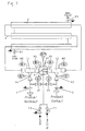
- Figure 1 shows a main pipe 1.2-1-1.1, the central portion 1 is guided through a heat exchanger W with a cooling water 8.1 and a cooling water return 8.2.
- the input section 1.2 of the main pipe opens with the interposition of a shut-V2 a product input line branch 2; to the exit section 1.1 of the main pipe includes a product outlet line branch 3 with the interposition of a shut-off device V4.
- a bypass line 5.1; 5.2 which contains for the transfer of a pig 4 from the output section 1.1 in the input section 1.2 of the main pipeline designed as pig injection ball valve V1 means of simplification reasons, only the ball 6 is shown schematically.
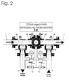
- the ball 6 of the ball valve V1 has a blind hole 6.1 for receiving the pig 4. It can from a Moch-receiving position in which the opening of the blind hole 6.1 to the output section 1.1. the main pipeline and thus to the receiving part 5.1 of the bypass line is directed, are rotated into the pig delivery position shown in Figure 1, in which the opening of the blind hole 6.1 the input section 1.2 of the main pipe and thus also the discharge part 5.2 of the bypass line faces , As shown in Figures 1 and 2, the blind hole 6.1 is connected via an input / output 6.2 and a first shut-off device V5 with the product output line branch 3 and a shut-off device V3 with the product input line branch 2.
- sensors M3 and M2 are arranged for detecting the presence or passage of a pig, and at the pig inlet ball valve V1 further sensors M1 and M4 are arranged, which on the position of the ball 6 and the Address the presence of a newt.
- the ball 6 is rotatable in a manner not shown between an insertion and a removal position in which after loosening a lid, not shown, the blind hole 6.1 is open to the outside.
- the input / output 6.2 can be connected via a shut-off device 7.1 to a compressed air source and via a shut-off device 7.2 to an exhaust air line.
- shut-off devices V1-V5 For actuating the shut-off devices V1-V5, a control device, which is not shown and basically known in its function, is used, to which the signals from the sensors M1-M4 are also supplied.
- the operation of the shut-off devices can be done pneumatically, for example.
- the shut-off devices V2, V3, V4 and V5 Prior to commissioning, the shut-off devices V2, V3, V4 and V5 are closed.
- the pig injection ball valve V1, in which a pig 4 is contained, which is indicated by the sensors M1 and M4, may be in a center position.
- the shut-off devices V2 and V4 To start up the shut-off devices V2 and V4 are opened so that the product to be conveyed through the product input line branch 2 the input section 1.2 and the guided through the heat exchanger W pipe 1 to the output section 1.1 and then flows into the product outlet line branch 3.
- the ball 6 of the pig inlet ball valve V1 is rotated to the position shown in Figure 1, in which the blind hole 6.1 to the discharge part 5.2 of the bypass line and thus to the input section 1.2 of Main pipeline is open. This position is indicated by the sensor M1.
- the shut-off device V3 is opened, and the shut-off device V2 is closed, so that the product flows via the input / output 6.2 in the blind hole 6.1 and the pig 4 is introduced into the input section 1.2, which is indicated by the sensor M2.
- the shut-off device V2 is opened to convey the pig 4 through the main pipeline.
- the shut-off device V3 is closed.
- the pig inlet ball valve V1 is rotated into the pig receiving position, in which the ball 6 is aligned so that the blind hole 6.1 is open to the receiving part 5.1 of the bypass line and thus to the output section 1.1 of the main pipeline.
- the shut-off device V5 is opened, and when the sensor M3 indicates that the pig has arrived in the outlet section 1.1, the shut-off device V4 is closed, so that the pig is inserted into the blind hole 6.1.
- product located can drain via the open shut-off device V5 in the product outlet line branch 3.
- the shut-off device V5 is closed again and the shut-off device V4 is opened.
- the pig inlet ball valve V1 can then be moved back to the center position, and a new cycle of a pig passage through the main pipeline can be initiated at any time.
- FIG. 3 shows an example of a pipeline leading from a storage container A 'to a filling station B'.
- the embodiment of Figures 1 and 2 corresponding parts of the device are designated by the same reference numerals, which are provided with an apostrophe mark.
- the storage container A is connected via the product input line branch 2 ', the main delivery line 1.2'-1'-1.1' and the product output line branch 3 'to the filling station B.
- the piping system may also be associated with a reactor, a Conti process unit or the like.
- the product is supplied by means of a pump 2.1 'through the shut-off device V2' the input section 1.2 'and conveyed after passing through the pipe section 1' and the output section 1.1 'via a shut-off valve V4' and the product output line branch 3 'in the filling station B.
- a bypass line 5.2'- 1.3'-5.1 ' is between the input and output sections 1.2 'and 1.1', in which for the introduction of a pig 4' in the main pipe 1.2'-1 '-1.1' as a pig inlet ball valve V1 ' trained device is located, from the sake of simplification, only the ball 6 'is shown schematically.
- the ball 6 'of the ball valve V1' is provided with a blind hole 6.1 'for the pig 4'.
- the ball 6 ' can be rotated from a pig receiving position in which the opening of the blind hole 6.1' the central portion 1.3 'of the bypass line and thus the output section 1.1' of the main pipe, are rotated into the pig discharge position shown in Figure 3, in which the opening the blind hole 6.1 'faces the inlet section 1.2' of the main pipeline.
- the blind hole 6.1 ' via an input / output 6.2' and a shut-off device V5 'to the input of the pump 2.1' and a shut-off device V3 'to the output of the pump 2.1' is connected.
- sensors for detecting the presence or passage of a pig are also arranged in the embodiment according to FIG. 3, namely a sensor M2 'at the input section 1.2', and a sensor M3 'at the output section 1.1'. and at the pig inlet ball valve V1 'the sensors M1' and M4 '.
- the operation of the device according to FIG. 3 is as follows: For actuating the shut-off devices V1 '- V5', in turn, a control device, not shown, are used, to which the signals of the sensors M1 '- M4' are supplied.
- the shut-off device V2 ', V3', V4 'and V5' are closed.
- the pig inlet ball valve V1 ' is located in the pig discharge position shown in FIG.
- the pump 2.1 ' is turned on, so that the product from the storage container A' is conveyed to the filling station B '.
- the pig inlet ball valve V1 must be in the position in which the opening of the blind hole 6.1 'to the discharge part 5.2' of the bypass line is open.
- the shut-off device V3 ' is opened and the shut-off device V2' is closed.
- shut-off device V5 ' is opened, so that in the line sections 5.1' and 1.3 'of the bypass line and in the blind hole 6.1' product located to flow to the inlet of the pump 2.1 'and the pig 4' can enter the blind hole 6.1 ', which is confirmed by the sensor M4 '.
- the obturator V5 ' is closed again, and the pig inlet ball valve V1' is rotated to the pig discharge position shown in Figure 3, so that a new cycle can be performed.
- the ball 6 'of the pig inlet ball valve V1' is rotatable into an insertion / removal position in which the blind hole 6.1 'is accessible from outside, so that a pig can be inserted or removed.
- the input / output 6.2 ' is connected via a shut-off element 7.1' to a compressed air source and via a shut-off element 7.2 'to an exhaust air line.
Landscapes
- Engineering & Computer Science (AREA)
- General Engineering & Computer Science (AREA)
- Mechanical Engineering (AREA)
- Chemical & Material Sciences (AREA)
- Combustion & Propulsion (AREA)
- Physics & Mathematics (AREA)
- Fluid Mechanics (AREA)
- Cleaning In General (AREA)
Claims (10)
- Dispositif en vue du nettoyage d'un pipeline principal au moyen d'un écouvillon qui est entraîné par le produit transporté à travers le pipeline principal à travers ce pipeline principal (1.2-1-1.3 ou 1.2'-1'-1'.1'), une ramification de conduite d'entrée de produit (2 ou 2') se raccordant à une section d'entrée (1.2 ou 1.2') du pipeline principal et une ramification de conduite de sortie de produit (3 ou 3') se raccordant à la section de sortie (1.1 ou 1.1') du pipeline principal, et une conduite de dérivation se trouvant entre la section d'entrée et de sortie du pipeline principal afin de transporter l'écouvillon de manière contrôlée par des soupapes depuis la section de sortie vers la section d'entrée du pipeline principal, caractérisé en ce qu'un robinet à boisseau sphérique d'éclusage d'écouvillon (V1 ou V1') est disposé dans la conduite de dérivation (5.1-5.2 ou 5.2'-1.3'-5.1') dont la sphère (6 ; 6') présente un alésage à trou borgne (6.1 ou 6.1') en vue de la réception de l'écouvillon (4 ou 4') et qui est rotatif entre une position de réception d'écouvillon dans laquelle l'ouverture de l'alésage à trou borgne (6.1 ; 6.1') est orientée vers la section de sortie (1.1 ou 1.1') du pipeline principal, et une section de distribution d'écouvillon dans laquelle l'ouverture de l'alésage à trou borgne est orientée vers la section d'entrée (1.2 ou 1.2') du pipeline principal.
- Dispositif selon la revendication 1, caractérisé en ce que l'alésage à trou borgne (6.1) de la sphère (6) du robinet à boisseau sphérique d'éclusage d'écouvillon (V1) peut être raccordé par l'intermédiaire d'un dispositif de blocage (V5) à la ramification de conduite de sortie de produit (3) et par l'intermédiaire d'un dispositif de blocage (V3) à la ramification de conduite d'entrée de produit (2).
- Dispositif selon la revendication 2, caractérisé en ce qu'un dispositif de blocage (V4) est disposé entre la ramification de conduite de sortie de produit (3) et la sortie (1.1) du pipeline principal et un dispositif de blocage (V2) est disposé entre la ramification de conduite d'entrée de produit (2) et l'entrée (1.2) du pipeline principal.
- Dispositif selon l'une quelconque des revendications 1 à 3, caractérisé en ce que des capteurs (M3, M2) sont disposés en vue de la détection de la présence et/ou du passage d'un écouvillon (4) dans la région de la section de sortie (1.1) du pipeline principal ou d'une partie de réception (5.1) de la conduite de dérivation et dans la région de la section d'entrée (1.2) du pipeline principal ou de la partie de distribution (5.2) de la conduite de dérivation.
- Dispositif selon la revendication 2, caractérisé en ce qu'une pompe de circulation (2.1') est intercalée dans la ramification de conduite d'entrée de produit (2').
- Dispositif selon la revendication 5, caractérisé en ce que l'alésage à trou borgne (6.1') de la sphère (6) du robinet à boisseau sphérique d'éclusage d'écouvillon (V1') peut être relié par l'intermédiaire d'un dispositif de blocage (V5') à l'entrée de la pompe de circulation (2.1') et par l'intermédiaire d'un dispositif de blocage (V3') à la sortie de la pompe de circulation (2.1).
- Dispositif selon la revendication 6, caractérisé en ce que la sortie (1.1') du pipeline principal est raccordée par l'intermédiaire d'un troisième dispositif de blocage (V4') à la ramification de conduite de sortie de produit (3') et l'entrée (1.2') du pipeline principal est raccordée par l'intermédiaire d'un quatrième dispositif de blocage (V2') à la sortie de la pompe de circulation (2.1').
- Dispositif selon l'une quelconque des revendications 5 à 7, caractérisé en ce que des capteurs (M3', M2') sont disposés en vue de la détection de la présence et/ou du passage d'un écouvillon dans la région de la section de sortie (1.1') du pipeline principal ou de la partie de réception (5.1') de la conduite de dérivation et dans la région de la section d'entrée (1.2') du pipeline principal ou de la partie de distribution (5.2') de la conduite de dérivation.
- Dispositif selon la revendication 2, caractérisé en ce que des capteurs (M4, M1 ; M4', M1') sont disposés en vue de la détection de la position de la sphère et/ou de la présence d'un écouvillon sur le robinet à boisseau sphérique d'éclusage d'écouvillon (V1 ; V1').
- Dispositif selon la revendication 1, caractérisé en ce que la sphère du robinet à boisseau sphérique d'éclusage d'écouvillon (V1) est rotative en vue d'insérer ou de prélever un écouvillon dans l'alésage à trou borgne (6.1 ; 6.1') entre une position d'insertion et de prélèvement.
Applications Claiming Priority (2)
| Application Number | Priority Date | Filing Date | Title |
|---|---|---|---|
| DE2003118902 DE10318902B3 (de) | 2003-04-26 | 2003-04-26 | Einrichtung zum Reinigen einer Hauptrohrleitung mittels eines Molches |
| DE10318902 | 2003-04-26 |
Publications (3)
| Publication Number | Publication Date |
|---|---|
| EP1470870A2 EP1470870A2 (fr) | 2004-10-27 |
| EP1470870A3 EP1470870A3 (fr) | 2005-07-20 |
| EP1470870B1 true EP1470870B1 (fr) | 2006-08-09 |
Family
ID=32798183
Family Applications (1)
| Application Number | Title | Priority Date | Filing Date |
|---|---|---|---|
| EP04009510A Expired - Lifetime EP1470870B1 (fr) | 2003-04-26 | 2004-04-22 | Installation pour nettoyer une conduite principale au moyen d'un racleur |
Country Status (3)
| Country | Link |
|---|---|
| EP (1) | EP1470870B1 (fr) |
| AT (1) | ATE335552T1 (fr) |
| DE (1) | DE10318902B3 (fr) |
Families Citing this family (7)
| Publication number | Priority date | Publication date | Assignee | Title |
|---|---|---|---|---|
| DE102006020079A1 (de) | 2006-04-29 | 2007-11-08 | Wolf, Peter, Dr. | Vorrichtung zur gleichzeitiger parallelen Reinigung von Rohrleitungen |
| US11692903B2 (en) | 2020-10-01 | 2023-07-04 | Saudi Arabian Oil Company | Valve diagnostic and performance system |
| US11441697B2 (en) * | 2020-10-01 | 2022-09-13 | Saudi Arabian Oil Company | Valve diagnostic and performance system |
| CN112855990B (zh) * | 2020-12-31 | 2022-09-30 | 重庆磐恒阀门有限公司 | 一种球形自清洁燃气切断阀 |
| CN112857139B (zh) * | 2021-03-31 | 2025-04-08 | 西安热工研究院有限公司 | 一种微通道换热器脉冲冲洗系统及方法 |
| CN115837384A (zh) * | 2021-09-18 | 2023-03-24 | 自贡新地佩尔阀门有限公司 | 一种清管装置 |
| CN117816673A (zh) * | 2023-03-15 | 2024-04-05 | 江苏佳泰汽车配件有限公司 | 一种汽车油路管的自动清洗设备 |
Family Cites Families (7)
| Publication number | Priority date | Publication date | Assignee | Title |
|---|---|---|---|---|
| US3817268A (en) * | 1973-06-12 | 1974-06-18 | C Kirkwood | Sphere launching valve |
| US3889708A (en) * | 1974-05-17 | 1975-06-17 | Chronister Dev Inc | Dual ball launch valve |
| JP3254722B2 (ja) * | 1992-03-06 | 2002-02-12 | 不二製油株式会社 | 配管清掃装置 |
| DE4237089C2 (de) * | 1992-11-03 | 2001-02-15 | Emtec Magnetics Gmbh | Vorrichtung zum Reinigen von Rohrleitungen |
| DE9303722U1 (de) * | 1993-03-13 | 1993-05-06 | Pfeiffer Chemie-Armaturenbau GmbH, 4152 Kempen | Einrichtung zum Ein- und Ausschleusen eines Molches in eine molchbare Leitung |
| CA2268193C (fr) * | 1997-05-30 | 2003-10-28 | Fmc Corporation | Systeme de distribution et de transport de cochonets pour puits sous-marins |
| JP2018032848A (ja) * | 2016-08-25 | 2018-03-01 | 株式会社村田製作所 | 半導体装置 |
-
2003
- 2003-04-26 DE DE2003118902 patent/DE10318902B3/de not_active Expired - Fee Related
-
2004
- 2004-04-22 EP EP04009510A patent/EP1470870B1/fr not_active Expired - Lifetime
- 2004-04-22 AT AT04009510T patent/ATE335552T1/de not_active IP Right Cessation
Also Published As
| Publication number | Publication date |
|---|---|
| EP1470870A2 (fr) | 2004-10-27 |
| DE10318902B3 (de) | 2004-09-02 |
| EP1470870A3 (fr) | 2005-07-20 |
| ATE335552T1 (de) | 2006-09-15 |
Similar Documents
| Publication | Publication Date | Title |
|---|---|---|
| EP1172153B1 (fr) | Racleur et son procédé d'utilisation dans une installation de revêtement | |
| EP3451892B1 (fr) | Dispositif panier de rinçage pour bouteilles et lave-vaisselle doté d'un tel dispositif | |
| EP0634229A1 (fr) | Procédé, assemblage et dispositif pour le nettoyage et revêtement interne d'une tuyauterie | |
| DE10318902B3 (de) | Einrichtung zum Reinigen einer Hauptrohrleitung mittels eines Molches | |
| DE60200966T2 (de) | Ventil | |
| EP1485215B1 (fr) | Dispositif pour attenuer les coups de belier dans des liquides s'ecoulant dans une conduite de liquide | |
| EP2268424B1 (fr) | Procédé et dispositif de traitement de fluides passant par des canalisations | |
| DE3642611A1 (de) | Verfahren zur reinigung von leitungssystemen | |
| DE102009057650A1 (de) | Förderrohrweiche | |
| DE102011106134A1 (de) | Vorrichtung und Verfahren zum Spülen von Kunststoffbehältnissen | |
| EP0890776A2 (fr) | Dispositif d'un tuyau de branchement | |
| WO2020058467A2 (fr) | Système de filtration d'un fluide, en particulier système de filtre bernoulli | |
| WO1986006823A1 (fr) | Ecluse de retenue de corps spheriques de nettoyage | |
| DE29603818U1 (de) | Absperrbare Leitungsverbindung zwischen kreuzenden, molchbaren Rohrleitungen | |
| WO2023094339A1 (fr) | Dispositif d'apport en matériau d'enduction | |
| DE9412043U1 (de) | Reinigbare Molchstation | |
| DE4237089C2 (de) | Vorrichtung zum Reinigen von Rohrleitungen | |
| EP3642521B1 (fr) | Tête de raccordement et noeuds de vannes | |
| DE102017010695B4 (de) | Verfahren und Armatur zum Reinigen eines Rohres | |
| DE202018106792U1 (de) | Ionentauscher-Anordnung | |
| EP3263957B1 (fr) | Soupape en ligne pouvant être raclée | |
| DE102006020079A1 (de) | Vorrichtung zur gleichzeitiger parallelen Reinigung von Rohrleitungen | |
| DE10351402A1 (de) | Installationswerkzeug und Verfahren zum Reparieren eines Rohres mit diesem Werkzeug | |
| CH679695A5 (en) | Air venting and/or cleaning heat exchanger pipes - thrusts elastic bodies of specified dia. by liq. through pipe | |
| EP1621256A1 (fr) | Procédé et dispositf permettant d'alimenter un dispositif d'application de peinture |
Legal Events
| Date | Code | Title | Description |
|---|---|---|---|
| PUAI | Public reference made under article 153(3) epc to a published international application that has entered the european phase |
Free format text: ORIGINAL CODE: 0009012 |
|
| AK | Designated contracting states |
Kind code of ref document: A2 Designated state(s): AT BE BG CH CY CZ DE DK EE ES FI FR GB GR HU IE IT LI LU MC NL PL PT RO SE SI SK TR |
|
| AX | Request for extension of the european patent |
Extension state: AL HR LT LV MK |
|
| RIN1 | Information on inventor provided before grant (corrected) |
Inventor name: DRUYEN, STEPHAN |
|
| PUAL | Search report despatched |
Free format text: ORIGINAL CODE: 0009013 |
|
| AK | Designated contracting states |
Kind code of ref document: A3 Designated state(s): AT BE BG CH CY CZ DK EE ES FI FR GB GR HU IE IT LI LU MC NL PL PT RO SE SI SK TR |
|
| AX | Request for extension of the european patent |
Extension state: AL HR LT LV MK |
|
| REG | Reference to a national code |
Ref country code: DE Ref legal event code: 8566 |
|
| GRAP | Despatch of communication of intention to grant a patent |
Free format text: ORIGINAL CODE: EPIDOSNIGR1 |
|
| 17P | Request for examination filed |
Effective date: 20060114 |
|
| AKX | Designation fees paid |
Designated state(s): AT BE BG CH CY CZ DK EE ES FI FR GB GR HU IE IT LI LU MC NL PL PT RO SE SI SK TR |
|
| GRAS | Grant fee paid |
Free format text: ORIGINAL CODE: EPIDOSNIGR3 |
|
| GRAA | (expected) grant |
Free format text: ORIGINAL CODE: 0009210 |
|
| AK | Designated contracting states |
Kind code of ref document: B1 Designated state(s): AT BE BG CH CY CZ DK EE ES FI FR GB GR HU IE IT LI LU MC NL PL PT RO SE SI SK TR |
|
| PG25 | Lapsed in a contracting state [announced via postgrant information from national office to epo] |
Ref country code: IT Free format text: LAPSE BECAUSE OF FAILURE TO SUBMIT A TRANSLATION OF THE DESCRIPTION OR TO PAY THE FEE WITHIN THE PRESCRIBED TIME-LIMIT;WARNING: LAPSES OF ITALIAN PATENTS WITH EFFECTIVE DATE BEFORE 2007 MAY HAVE OCCURRED AT ANY TIME BEFORE 2007. THE CORRECT EFFECTIVE DATE MAY BE DIFFERENT FROM THE ONE RECORDED. Effective date: 20060809 Ref country code: CZ Free format text: LAPSE BECAUSE OF FAILURE TO SUBMIT A TRANSLATION OF THE DESCRIPTION OR TO PAY THE FEE WITHIN THE PRESCRIBED TIME-LIMIT Effective date: 20060809 Ref country code: IE Free format text: LAPSE BECAUSE OF FAILURE TO SUBMIT A TRANSLATION OF THE DESCRIPTION OR TO PAY THE FEE WITHIN THE PRESCRIBED TIME-LIMIT Effective date: 20060809 Ref country code: GB Free format text: LAPSE BECAUSE OF FAILURE TO SUBMIT A TRANSLATION OF THE DESCRIPTION OR TO PAY THE FEE WITHIN THE PRESCRIBED TIME-LIMIT Effective date: 20060809 Ref country code: RO Free format text: LAPSE BECAUSE OF FAILURE TO SUBMIT A TRANSLATION OF THE DESCRIPTION OR TO PAY THE FEE WITHIN THE PRESCRIBED TIME-LIMIT Effective date: 20060809 Ref country code: FI Free format text: LAPSE BECAUSE OF FAILURE TO SUBMIT A TRANSLATION OF THE DESCRIPTION OR TO PAY THE FEE WITHIN THE PRESCRIBED TIME-LIMIT Effective date: 20060809 Ref country code: NL Free format text: LAPSE BECAUSE OF FAILURE TO SUBMIT A TRANSLATION OF THE DESCRIPTION OR TO PAY THE FEE WITHIN THE PRESCRIBED TIME-LIMIT Effective date: 20060809 Ref country code: SI Free format text: LAPSE BECAUSE OF FAILURE TO SUBMIT A TRANSLATION OF THE DESCRIPTION OR TO PAY THE FEE WITHIN THE PRESCRIBED TIME-LIMIT Effective date: 20060809 Ref country code: SK Free format text: LAPSE BECAUSE OF FAILURE TO SUBMIT A TRANSLATION OF THE DESCRIPTION OR TO PAY THE FEE WITHIN THE PRESCRIBED TIME-LIMIT Effective date: 20060809 Ref country code: PL Free format text: LAPSE BECAUSE OF FAILURE TO SUBMIT A TRANSLATION OF THE DESCRIPTION OR TO PAY THE FEE WITHIN THE PRESCRIBED TIME-LIMIT Effective date: 20060809 |
|
| REG | Reference to a national code |
Ref country code: GB Ref legal event code: FG4D Free format text: NOT ENGLISH |
|
| REG | Reference to a national code |
Ref country code: CH Ref legal event code: EP |
|
| REG | Reference to a national code |
Ref country code: IE Ref legal event code: FG4D Free format text: LANGUAGE OF EP DOCUMENT: GERMAN |
|
| PG25 | Lapsed in a contracting state [announced via postgrant information from national office to epo] |
Ref country code: SE Free format text: LAPSE BECAUSE OF FAILURE TO SUBMIT A TRANSLATION OF THE DESCRIPTION OR TO PAY THE FEE WITHIN THE PRESCRIBED TIME-LIMIT Effective date: 20061109 Ref country code: DK Free format text: LAPSE BECAUSE OF FAILURE TO SUBMIT A TRANSLATION OF THE DESCRIPTION OR TO PAY THE FEE WITHIN THE PRESCRIBED TIME-LIMIT Effective date: 20061109 Ref country code: BG Free format text: LAPSE BECAUSE OF FAILURE TO SUBMIT A TRANSLATION OF THE DESCRIPTION OR TO PAY THE FEE WITHIN THE PRESCRIBED TIME-LIMIT Effective date: 20061109 |
|
| PG25 | Lapsed in a contracting state [announced via postgrant information from national office to epo] |
Ref country code: ES Free format text: LAPSE BECAUSE OF FAILURE TO SUBMIT A TRANSLATION OF THE DESCRIPTION OR TO PAY THE FEE WITHIN THE PRESCRIBED TIME-LIMIT Effective date: 20061120 |
|
| REG | Reference to a national code |
Ref country code: CH Ref legal event code: NV Representative=s name: R. A. EGLI & CO. PATENTANWAELTE |
|
| PG25 | Lapsed in a contracting state [announced via postgrant information from national office to epo] |
Ref country code: PT Free format text: LAPSE BECAUSE OF FAILURE TO SUBMIT A TRANSLATION OF THE DESCRIPTION OR TO PAY THE FEE WITHIN THE PRESCRIBED TIME-LIMIT Effective date: 20070109 |
|
| NLV1 | Nl: lapsed or annulled due to failure to fulfill the requirements of art. 29p and 29m of the patents act | ||
| GBV | Gb: ep patent (uk) treated as always having been void in accordance with gb section 77(7)/1977 [no translation filed] |
Effective date: 20060809 |
|
| REG | Reference to a national code |
Ref country code: IE Ref legal event code: FD4D |
|
| EN | Fr: translation not filed | ||
| PLBE | No opposition filed within time limit |
Free format text: ORIGINAL CODE: 0009261 |
|
| STAA | Information on the status of an ep patent application or granted ep patent |
Free format text: STATUS: NO OPPOSITION FILED WITHIN TIME LIMIT |
|
| 26N | No opposition filed |
Effective date: 20070510 |
|
| BERE | Be: lapsed |
Owner name: PFEIFFER CHEMIE-ARMATURENBAU G.M.B.H. Effective date: 20070430 |
|
| PG25 | Lapsed in a contracting state [announced via postgrant information from national office to epo] |
Ref country code: BE Free format text: LAPSE BECAUSE OF NON-PAYMENT OF DUE FEES Effective date: 20070430 |
|
| PG25 | Lapsed in a contracting state [announced via postgrant information from national office to epo] |
Ref country code: FR Free format text: LAPSE BECAUSE OF FAILURE TO SUBMIT A TRANSLATION OF THE DESCRIPTION OR TO PAY THE FEE WITHIN THE PRESCRIBED TIME-LIMIT Effective date: 20070511 Ref country code: GR Free format text: LAPSE BECAUSE OF FAILURE TO SUBMIT A TRANSLATION OF THE DESCRIPTION OR TO PAY THE FEE WITHIN THE PRESCRIBED TIME-LIMIT Effective date: 20061110 |
|
| PG25 | Lapsed in a contracting state [announced via postgrant information from national office to epo] |
Ref country code: EE Free format text: LAPSE BECAUSE OF FAILURE TO SUBMIT A TRANSLATION OF THE DESCRIPTION OR TO PAY THE FEE WITHIN THE PRESCRIBED TIME-LIMIT Effective date: 20060809 |
|
| PGFP | Annual fee paid to national office [announced via postgrant information from national office to epo] |
Ref country code: CH Payment date: 20080424 Year of fee payment: 5 Ref country code: LU Payment date: 20080429 Year of fee payment: 5 |
|
| PGFP | Annual fee paid to national office [announced via postgrant information from national office to epo] |
Ref country code: AT Payment date: 20080423 Year of fee payment: 5 |
|
| PG25 | Lapsed in a contracting state [announced via postgrant information from national office to epo] |
Ref country code: FR Free format text: LAPSE BECAUSE OF FAILURE TO SUBMIT A TRANSLATION OF THE DESCRIPTION OR TO PAY THE FEE WITHIN THE PRESCRIBED TIME-LIMIT Effective date: 20060809 |
|
| PG25 | Lapsed in a contracting state [announced via postgrant information from national office to epo] |
Ref country code: MC Free format text: LAPSE BECAUSE OF NON-PAYMENT OF DUE FEES Effective date: 20070430 |
|
| PG25 | Lapsed in a contracting state [announced via postgrant information from national office to epo] |
Ref country code: CY Free format text: LAPSE BECAUSE OF FAILURE TO SUBMIT A TRANSLATION OF THE DESCRIPTION OR TO PAY THE FEE WITHIN THE PRESCRIBED TIME-LIMIT Effective date: 20060809 |
|
| PG25 | Lapsed in a contracting state [announced via postgrant information from national office to epo] |
Ref country code: TR Free format text: LAPSE BECAUSE OF FAILURE TO SUBMIT A TRANSLATION OF THE DESCRIPTION OR TO PAY THE FEE WITHIN THE PRESCRIBED TIME-LIMIT Effective date: 20060809 Ref country code: HU Free format text: LAPSE BECAUSE OF FAILURE TO SUBMIT A TRANSLATION OF THE DESCRIPTION OR TO PAY THE FEE WITHIN THE PRESCRIBED TIME-LIMIT Effective date: 20070210 |
|
| REG | Reference to a national code |
Ref country code: CH Ref legal event code: PL |
|
| PG25 | Lapsed in a contracting state [announced via postgrant information from national office to epo] |
Ref country code: AT Free format text: LAPSE BECAUSE OF NON-PAYMENT OF DUE FEES Effective date: 20090422 Ref country code: CH Free format text: LAPSE BECAUSE OF NON-PAYMENT OF DUE FEES Effective date: 20090430 Ref country code: LI Free format text: LAPSE BECAUSE OF NON-PAYMENT OF DUE FEES Effective date: 20090430 |
|
| PG25 | Lapsed in a contracting state [announced via postgrant information from national office to epo] |
Ref country code: LU Free format text: LAPSE BECAUSE OF NON-PAYMENT OF DUE FEES Effective date: 20090422 |