EP1470942B1 - Anordnung für die Befestigung eines Trägers für einen Sonnenvorhang - Google Patents
Anordnung für die Befestigung eines Trägers für einen Sonnenvorhang Download PDFInfo
- Publication number
- EP1470942B1 EP1470942B1 EP20040300214 EP04300214A EP1470942B1 EP 1470942 B1 EP1470942 B1 EP 1470942B1 EP 20040300214 EP20040300214 EP 20040300214 EP 04300214 A EP04300214 A EP 04300214A EP 1470942 B1 EP1470942 B1 EP 1470942B1
- Authority
- EP
- European Patent Office
- Prior art keywords
- support
- arrangement
- pin
- wall
- clip
- Prior art date
- Legal status (The legal status is an assumption and is not a legal conclusion. Google has not performed a legal analysis and makes no representation as to the accuracy of the status listed.)
- Expired - Lifetime
Links
- 230000000295 complement effect Effects 0.000 claims description 8
- 238000003780 insertion Methods 0.000 claims description 6
- 230000037431 insertion Effects 0.000 claims description 6
- 239000002184 metal Substances 0.000 claims description 3
- 238000012216 screening Methods 0.000 claims 1
- 230000000475 sunscreen effect Effects 0.000 claims 1
- 239000000516 sunscreening agent Substances 0.000 claims 1
- 241000920340 Pion Species 0.000 description 9
- 208000031968 Cadaver Diseases 0.000 description 2
- 230000000717 retained effect Effects 0.000 description 2
- 238000004873 anchoring Methods 0.000 description 1
- 230000005489 elastic deformation Effects 0.000 description 1
- 238000000465 moulding Methods 0.000 description 1
- 238000003466 welding Methods 0.000 description 1
Images
Classifications
-
- B—PERFORMING OPERATIONS; TRANSPORTING
- B60—VEHICLES IN GENERAL
- B60J—WINDOWS, WINDSCREENS, NON-FIXED ROOFS, DOORS, OR SIMILAR DEVICES FOR VEHICLES; REMOVABLE EXTERNAL PROTECTIVE COVERINGS SPECIALLY ADAPTED FOR VEHICLES
- B60J1/00—Windows; Windscreens; Accessories therefor
- B60J1/20—Accessories, e.g. wind deflectors, blinds
- B60J1/2011—Blinds; curtains or screens reducing heat or light intensity
- B60J1/2013—Roller blinds
- B60J1/2036—Roller blinds characterised by structural elements
- B60J1/2038—Storage boxes
-
- B—PERFORMING OPERATIONS; TRANSPORTING
- B60—VEHICLES IN GENERAL
- B60J—WINDOWS, WINDSCREENS, NON-FIXED ROOFS, DOORS, OR SIMILAR DEVICES FOR VEHICLES; REMOVABLE EXTERNAL PROTECTIVE COVERINGS SPECIALLY ADAPTED FOR VEHICLES
- B60J1/00—Windows; Windscreens; Accessories therefor
- B60J1/20—Accessories, e.g. wind deflectors, blinds
- B60J1/2011—Blinds; curtains or screens reducing heat or light intensity
- B60J1/2013—Roller blinds
- B60J1/2063—Mounting arrangements for roller blind or its storage box, e.g. integration into beltline or window frame
-
- B—PERFORMING OPERATIONS; TRANSPORTING
- B60—VEHICLES IN GENERAL
- B60J—WINDOWS, WINDSCREENS, NON-FIXED ROOFS, DOORS, OR SIMILAR DEVICES FOR VEHICLES; REMOVABLE EXTERNAL PROTECTIVE COVERINGS SPECIALLY ADAPTED FOR VEHICLES
- B60J1/00—Windows; Windscreens; Accessories therefor
- B60J1/20—Accessories, e.g. wind deflectors, blinds
- B60J1/2011—Blinds; curtains or screens reducing heat or light intensity
- B60J1/2013—Roller blinds
- B60J1/2066—Arrangement of blinds in vehicles
- B60J1/2069—Arrangement of blinds in vehicles of multiple blinds, e.g. more than one blind per window or per actuation system
-
- B—PERFORMING OPERATIONS; TRANSPORTING
- B60—VEHICLES IN GENERAL
- B60J—WINDOWS, WINDSCREENS, NON-FIXED ROOFS, DOORS, OR SIMILAR DEVICES FOR VEHICLES; REMOVABLE EXTERNAL PROTECTIVE COVERINGS SPECIALLY ADAPTED FOR VEHICLES
- B60J1/00—Windows; Windscreens; Accessories therefor
- B60J1/20—Accessories, e.g. wind deflectors, blinds
- B60J1/2011—Blinds; curtains or screens reducing heat or light intensity
- B60J1/2013—Roller blinds
- B60J1/2066—Arrangement of blinds in vehicles
- B60J1/2072—Blinds with inclined or vertical orientation of the winding axis
-
- B—PERFORMING OPERATIONS; TRANSPORTING
- B60—VEHICLES IN GENERAL
- B60J—WINDOWS, WINDSCREENS, NON-FIXED ROOFS, DOORS, OR SIMILAR DEVICES FOR VEHICLES; REMOVABLE EXTERNAL PROTECTIVE COVERINGS SPECIALLY ADAPTED FOR VEHICLES
- B60J1/00—Windows; Windscreens; Accessories therefor
- B60J1/20—Accessories, e.g. wind deflectors, blinds
- B60J1/2011—Blinds; curtains or screens reducing heat or light intensity
- B60J1/2013—Roller blinds
- B60J1/2066—Arrangement of blinds in vehicles
- B60J1/2086—Arrangement of blinds in vehicles specially adapted for openable windows, e.g. side window
Definitions
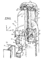
- the invention relates to an arrangement for attaching a curtain support sun visor.
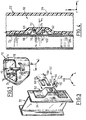
- the cavity 68 has a shape substantially complementary to the attachment plate 52 and its boss 54.
- arms 88, 90 of the clip 86 may comprise interlocking means (not shown) capable of cooperating with the fixing pin 64, for example by elastic deformation, so as to retain the clip 86 transversely. in mounted position.
Landscapes
- Engineering & Computer Science (AREA)
- Mechanical Engineering (AREA)
- Connection Of Plates (AREA)
- Window Of Vehicle (AREA)
Claims (10)
- Anordnung (50) für die Befestigung eines Sonnenvorhangträgers (22) an der inneren Wand (24) einer im Allgemeinen vertikalen Säule (20) eines seitlichen Fensters (12) des Kraftfahrzeugs, von der Art, bei welcher der Träger (22) an der Säule (20) derart befestigt ist, dass der Vorhang (34, 36) mindestens eine Verdunkelungsstellung, in welcher der Vorhang (34, 36) mindestens einen Teil des Fensters (12) bedeckt, und eine eingezogene Stellung einnehmen kann, dadurch gekennzeichnet, dass:- die innere Wand (24) der Säule (20) mindestens eine Befestigungsplatte (52) aufweist, die mit einem axialen Loch (62) versehen ist,- die äußere Wand (28) des Trägers (22) mindestens einen Befestigungsklotz (64) aufweist, der sich axial in Richtung nach außen erstreckt, um in dem Loch (62) der Platte (52) aufgenommen zu werden, und welcher mindestens eine im Wesentlichen radiale Anschlagoberfläche (100, 102) aufweist, die in Richtung nach innen gerichtet ist,und dass in montierter Stellung des Trägers (22) an der Säule (20) eine Klammer (86) transversal von der Seite der äußeren Fläche der Befestigungsplatte (52) derart eingeführt ist, dass sich eine im Wesentlichen radiale Anlageoberfläche (92, 94) der Klammer (86), die in Richtung nach außen gerichtet ist, axial gegenüber der Anschlagoberfläche (100, 102) des Klotzes (64) positioniert und axial den Klotz (64) in dem Loch (62) hält.
- Anordnung (50) nach dem vorherigen Anspruch, dadurch gekennzeichnet, dass die Klammer (86) zwei Anlageoberflächen (92, 94) aufweist, die jeweils zu zwei Armen (88, 90) der Klammer (86) gehören, die parallel zu der transversalen. Einführrichtung sind, und dass der Klotz (64) zwei im Wesentlichen diametral gegenüberliegende Anschlagoberflächen (100, 102) aufweist, die jeweils zu jeder Anlageoberfläche (92, 94) der Klammer (86) gehören.
- Anordnung (50) nach irgendeinem der vorangegangenen Ansprüche, dadurch gekennzeichnet, dass der Körper (70) des Klotzes (64) mit mindestens einer transversalen Nut (72, 74) versehen ist und dass eine im Wesentlichen radiale Oberfläche (100,102) der Nut (72, 74) die Anschlagoberfläche des Klotzes (64) bildet.
- Anordnung (50) nach irgendeinem der vorangegangenen Ansprüche, dadurch gekennzeichnet, dass der Klotz (64) sich axial ausgehend von dem Boden eines Hohlraums (68) erstreckt, der in der äußeren Wand (28) des Trägers (22) realisiert ist, und dass die Befestigungsplatte (52) einen zu dem Hohlraum (68) im Allgemeinen komplementären Vorsprung (54) bildet, wobei das Loch (62) im Allgemeinen an der Spitze des Vorsprungs (54) derart angeordnet ist, um den axialen Raum zwischen der äußeren Wand (28) des Trägers (22) und der inneren Wand (24) der Säule (20) zu minimieren.
- Anordnung (50) nach dem vorangegangenen Anspruch, dadurch gekennzeichnet, dass der Hohlraum (68) eine axiale, im Wesentlichen vertikale Wand (76) aufweist, die mit einer transversalen Öffnung (84) versehen ist, um den Durchgang der Klammer (86) zu erlauben.
- Anordnung (50) nach dem vorangegangenen Anspruch, dadurch gekennzeichnet, dass der Träger (22) eine Aufnahme (108) aufweist, die zum Aufnehmen der Klammer (86) auf komplementäre Art und Weise vorgesehen ist.
- Anordnung (50) nach dem vorangegangenen Anspruch, dadurch gekennzeichnet, dass die Aufnahme (108) Mittel für die transversale Führung der Klammer (86) aufweist.
- Anordnung (50) nach irgendeinem der vorangegangenen Ansprüche, dadurch gekennzeichnet, dass der Körper (70) des Klotzes (64) im Allgemeinen zylindrisch ist.
- Anordnung (50) nach irgendeinem der vorangegangenen Ansprüche, dadurch gekennzeichnet, dass die Befestigungsplatte (52) an der Säule (20) des Fensters (12) angefügt ist.
- Anordnung (50) nach dem vorangegangenen Anspruch, dadurch gekennzeichnet, dass die Befestigungsplatte (52) aus Blech realisiert ist und dass sie ah der Säule (20) des Fensters (12) angeschweißt ist.
Applications Claiming Priority (2)
| Application Number | Priority Date | Filing Date | Title |
|---|---|---|---|
| FR0304969 | 2003-04-23 | ||
| FR0304969A FR2854105B1 (fr) | 2003-04-23 | 2003-04-23 | Agencement pour la fixation d'un support de rideau pare-soleil |
Publications (2)
| Publication Number | Publication Date |
|---|---|
| EP1470942A1 EP1470942A1 (de) | 2004-10-27 |
| EP1470942B1 true EP1470942B1 (de) | 2007-03-21 |
Family
ID=32947363
Family Applications (1)
| Application Number | Title | Priority Date | Filing Date |
|---|---|---|---|
| EP20040300214 Expired - Lifetime EP1470942B1 (de) | 2003-04-23 | 2004-04-21 | Anordnung für die Befestigung eines Trägers für einen Sonnenvorhang |
Country Status (4)
| Country | Link |
|---|---|
| EP (1) | EP1470942B1 (de) |
| DE (1) | DE602004005372T2 (de) |
| ES (1) | ES2280020T3 (de) |
| FR (1) | FR2854105B1 (de) |
Cited By (1)
| Publication number | Priority date | Publication date | Assignee | Title |
|---|---|---|---|---|
| US11670788B2 (en) | 2008-12-02 | 2023-06-06 | General Electric Company | Apparatus and method for high efficiency operation of fuel cell systems |
Families Citing this family (1)
| Publication number | Priority date | Publication date | Assignee | Title |
|---|---|---|---|---|
| FR2904265B1 (fr) * | 2006-07-28 | 2008-11-21 | Wagon Sas | Dispositif d'occultation a element de maitien, et vehicule correspondant |
Family Cites Families (3)
| Publication number | Priority date | Publication date | Assignee | Title |
|---|---|---|---|---|
| DE3822378C2 (de) * | 1988-07-01 | 1994-10-27 | Bayerische Motoren Werke Ag | Fensterrollo für ein Kraftfahrzeug |
| DE50000785D1 (de) * | 2000-03-03 | 2003-01-02 | Schwab Technik Gmbh | Scheibenrollo-Vorrichtung für Fahrzeugscheiben |
| US6477485B1 (en) | 2000-10-27 | 2002-11-05 | Otis Elevator Company | Monitoring system behavior using empirical distributions and cumulative distribution norms |
-
2003
- 2003-04-23 FR FR0304969A patent/FR2854105B1/fr not_active Expired - Fee Related
-
2004
- 2004-04-21 ES ES04300214T patent/ES2280020T3/es not_active Expired - Lifetime
- 2004-04-21 DE DE602004005372T patent/DE602004005372T2/de not_active Expired - Lifetime
- 2004-04-21 EP EP20040300214 patent/EP1470942B1/de not_active Expired - Lifetime
Cited By (1)
| Publication number | Priority date | Publication date | Assignee | Title |
|---|---|---|---|---|
| US11670788B2 (en) | 2008-12-02 | 2023-06-06 | General Electric Company | Apparatus and method for high efficiency operation of fuel cell systems |
Also Published As
| Publication number | Publication date |
|---|---|
| FR2854105A1 (fr) | 2004-10-29 |
| ES2280020T3 (es) | 2007-09-01 |
| EP1470942A1 (de) | 2004-10-27 |
| DE602004005372T2 (de) | 2007-11-29 |
| FR2854105B1 (fr) | 2005-07-01 |
| DE602004005372D1 (de) | 2007-05-03 |
Similar Documents
| Publication | Publication Date | Title |
|---|---|---|
| EP3681746B1 (de) | Fensterdichtungsband mit einfacher montage | |
| FR2736025A1 (fr) | Essuie-glace pour vehicule automobile comportant un connecteur muni d'un capot articule | |
| FR2952900A1 (fr) | Cle extractible pour joint de vitrage et procede d'extraction s'y rapportant | |
| EP2648996A1 (de) | Vorrichtung und anordnung zur stütze eines scheibenwischerpaares und entsprechende verpackung sowie montageverfahren | |
| EP0538093A1 (de) | Verkleideter Scheibenwischer, insbesondere für Kraftfahrzeug | |
| EP3045357B1 (de) | Abdeckung eines scheibenwischers, die für die abdeckung des endteils eines scheibenwischerarms konfiguriert ist | |
| EP1470942B1 (de) | Anordnung für die Befestigung eines Trägers für einen Sonnenvorhang | |
| EP0667261A1 (de) | Gepäckträger für Kraftfahrzeuge | |
| FR2696393A1 (fr) | Essuie-glace de véhicule automobile, tête d'entraînement pour un tel essuie-glace, et coiffe de protection de la tête d'entraînement. | |
| EP0985567B1 (de) | Rollo mit Gehäuse zur Bildung eines Türoberteiles; Tür und Verfahren dafür | |
| EP3375675B1 (de) | Abdeckung, verbindungsvorrichtung für die montage eines scheibenwischerblatts auf einem entsprechenden scheibenwischerarm, und entsprechendes scheibenwischsystem | |
| EP2089245B1 (de) | Heckklappenkonstruktion für ein automobil und automobil mit derartiger konstruktion | |
| EP0724052B1 (de) | Türgriff eines Kraftfahrzeugs zur schnellen Montage durch ein Keil-Nockensystem | |
| FR3140592A1 (fr) | Portière de véhicule comprenant un logement pour grattoir de dégivrage et grattoir de dégivrage associé | |
| EP0169499B1 (de) | Karton und Vorrichtung zum VerschlieBen des Kartons | |
| FR2878587A1 (fr) | Clip pour fixation d'un enjoliveur de pavillon d'un vehicule ensembles formes par de tels clips et un enjoliveur de pavillon, et vehicule les comportant | |
| EP0567389B1 (de) | Wischarm mit wenigstens einer Anpressdruckfeder | |
| EP4164905B1 (de) | Kraftfahrzeugtürverkleidung | |
| EP3727915B1 (de) | Dichtung für ein kraftfahrzeug umfassend mindestens einen befestigungsclip | |
| EP3983244B1 (de) | Montageführung für einen panhard-stab eines kraftfahrzeugs | |
| EP2050603B1 (de) | Rollo mit Aufwickelvorrichtung für Kraftfahrzeug, das mit einem mit Clips versehenen Befestigungssystem auf dem Rahmen ausgestattet ist, entsprechender Rahmen und entsprechendes Fahrzeug | |
| FR2713170A1 (fr) | Porte-plaque minéralogique pour véhicule automobile. | |
| EP0566487B1 (de) | Vorrichtung zum Befestigen eines Überzuges eines Polstersitzes; Verfahren zu ihrer Herstellung und ihrer Montage | |
| FR2751272A1 (fr) | Store d'occultation d'une baie de vehicule | |
| WO2024126029A1 (fr) | Emballage pour balai d'essuie-glace |
Legal Events
| Date | Code | Title | Description |
|---|---|---|---|
| PUAI | Public reference made under article 153(3) epc to a published international application that has entered the european phase |
Free format text: ORIGINAL CODE: 0009012 |
|
| AK | Designated contracting states |
Kind code of ref document: A1 Designated state(s): AT BE BG CH CY CZ DE DK EE ES FI FR GB GR HU IE IT LI LU MC NL PL PT RO SE SI SK TR |
|
| AX | Request for extension of the european patent |
Extension state: AL HR LT LV MK |
|
| 17P | Request for examination filed |
Effective date: 20050331 |
|
| AKX | Designation fees paid |
Designated state(s): AT BE BG CH CY CZ DE DK EE ES FI FR GB GR HU IE IT LI LU MC NL PL PT RO SE SI SK TR |
|
| RBV | Designated contracting states (corrected) |
Designated state(s): AT BE BG CH CY CZ DE DK EE ES FI FR GB GR HU IE IT LI LU MC NL PL PT RO SE SI SK TR |
|
| GRAP | Despatch of communication of intention to grant a patent |
Free format text: ORIGINAL CODE: EPIDOSNIGR1 |
|
| GRAS | Grant fee paid |
Free format text: ORIGINAL CODE: EPIDOSNIGR3 |
|
| GRAA | (expected) grant |
Free format text: ORIGINAL CODE: 0009210 |
|
| AK | Designated contracting states |
Kind code of ref document: B1 Designated state(s): BE DE ES GB |
|
| REG | Reference to a national code |
Ref country code: GB Ref legal event code: FG4D Free format text: NOT ENGLISH |
|
| GBT | Gb: translation of ep patent filed (gb section 77(6)(a)/1977) |
Effective date: 20070404 |
|
| REF | Corresponds to: |
Ref document number: 602004005372 Country of ref document: DE Date of ref document: 20070503 Kind code of ref document: P |
|
| REG | Reference to a national code |
Ref country code: ES Ref legal event code: FG2A Ref document number: 2280020 Country of ref document: ES Kind code of ref document: T3 |
|
| PLBE | No opposition filed within time limit |
Free format text: ORIGINAL CODE: 0009261 |
|
| STAA | Information on the status of an ep patent application or granted ep patent |
Free format text: STATUS: NO OPPOSITION FILED WITHIN TIME LIMIT |
|
| 26N | No opposition filed |
Effective date: 20071227 |
|
| PGFP | Annual fee paid to national office [announced via postgrant information from national office to epo] |
Ref country code: DE Payment date: 20160421 Year of fee payment: 13 Ref country code: GB Payment date: 20160421 Year of fee payment: 13 Ref country code: ES Payment date: 20160413 Year of fee payment: 13 |
|
| PGFP | Annual fee paid to national office [announced via postgrant information from national office to epo] |
Ref country code: BE Payment date: 20160420 Year of fee payment: 13 |
|
| REG | Reference to a national code |
Ref country code: DE Ref legal event code: R119 Ref document number: 602004005372 Country of ref document: DE |
|
| GBPC | Gb: european patent ceased through non-payment of renewal fee |
Effective date: 20170421 |
|
| PG25 | Lapsed in a contracting state [announced via postgrant information from national office to epo] |
Ref country code: DE Free format text: LAPSE BECAUSE OF NON-PAYMENT OF DUE FEES Effective date: 20171103 |
|
| PG25 | Lapsed in a contracting state [announced via postgrant information from national office to epo] |
Ref country code: GB Free format text: LAPSE BECAUSE OF NON-PAYMENT OF DUE FEES Effective date: 20170421 |
|
| REG | Reference to a national code |
Ref country code: BE Ref legal event code: MM Effective date: 20170430 |
|
| PG25 | Lapsed in a contracting state [announced via postgrant information from national office to epo] |
Ref country code: BE Free format text: LAPSE BECAUSE OF NON-PAYMENT OF DUE FEES Effective date: 20170430 |
|
| REG | Reference to a national code |
Ref country code: ES Ref legal event code: FD2A Effective date: 20180629 |
|
| PG25 | Lapsed in a contracting state [announced via postgrant information from national office to epo] |
Ref country code: ES Free format text: LAPSE BECAUSE OF NON-PAYMENT OF DUE FEES Effective date: 20170422 |