EP1470980A1 - Servomoteur d'assistance pneumatique au freinage à bruit de fonctionnement réduit - Google Patents
Servomoteur d'assistance pneumatique au freinage à bruit de fonctionnement réduit Download PDFInfo
- Publication number
- EP1470980A1 EP1470980A1 EP04008298A EP04008298A EP1470980A1 EP 1470980 A1 EP1470980 A1 EP 1470980A1 EP 04008298 A EP04008298 A EP 04008298A EP 04008298 A EP04008298 A EP 04008298A EP 1470980 A1 EP1470980 A1 EP 1470980A1
- Authority
- EP
- European Patent Office
- Prior art keywords
- piston
- pneumatic
- braking
- plunger
- pneumatic brake
- Prior art date
- Legal status (The legal status is an assumption and is not a legal conclusion. Google has not performed a legal analysis and makes no representation as to the accuracy of the status listed.)
- Granted
Links
- 238000006243 chemical reaction Methods 0.000 claims description 31
- 238000013016 damping Methods 0.000 claims description 29
- 239000000463 material Substances 0.000 claims description 8
- 230000003534 oscillatory effect Effects 0.000 claims description 8
- 238000004891 communication Methods 0.000 claims description 5
- 229920001971 elastomer Polymers 0.000 claims description 5
- 230000008878 coupling Effects 0.000 claims description 4
- 238000010168 coupling process Methods 0.000 claims description 4
- 238000005859 coupling reaction Methods 0.000 claims description 4
- 239000000806 elastomer Substances 0.000 claims description 4
- 239000012530 fluid Substances 0.000 claims description 4
- 239000002783 friction material Substances 0.000 claims 2
- 230000010355 oscillation Effects 0.000 abstract description 2
- 230000035939 shock Effects 0.000 abstract 2
- 238000006073 displacement reaction Methods 0.000 description 8
- 239000000523 sample Substances 0.000 description 6
- 230000000694 effects Effects 0.000 description 3
- 230000006835 compression Effects 0.000 description 2
- 238000007906 compression Methods 0.000 description 2
- 230000002457 bidirectional effect Effects 0.000 description 1
- PCHJSUWPFVWCPO-UHFFFAOYSA-N gold Chemical compound [Au] PCHJSUWPFVWCPO-UHFFFAOYSA-N 0.000 description 1
- 239000010931 gold Substances 0.000 description 1
- 229910052737 gold Inorganic materials 0.000 description 1
- 238000009434 installation Methods 0.000 description 1
- 238000009413 insulation Methods 0.000 description 1
- 230000007257 malfunction Effects 0.000 description 1
- 238000004519 manufacturing process Methods 0.000 description 1
- 239000012528 membrane Substances 0.000 description 1
- 238000000465 moulding Methods 0.000 description 1
- 238000010137 moulding (plastic) Methods 0.000 description 1
- 230000003071 parasitic effect Effects 0.000 description 1
- 230000010287 polarization Effects 0.000 description 1
- 238000005096 rolling process Methods 0.000 description 1
Images




Classifications
-
- B—PERFORMING OPERATIONS; TRANSPORTING
- B60—VEHICLES IN GENERAL
- B60T—VEHICLE BRAKE CONTROL SYSTEMS OR PARTS THEREOF; BRAKE CONTROL SYSTEMS OR PARTS THEREOF, IN GENERAL; ARRANGEMENT OF BRAKING ELEMENTS ON VEHICLES IN GENERAL; PORTABLE DEVICES FOR PREVENTING UNWANTED MOVEMENT OF VEHICLES; VEHICLE MODIFICATIONS TO FACILITATE COOLING OF BRAKES
- B60T13/00—Transmitting braking action from initiating means to ultimate brake actuator with power assistance or drive; Brake systems incorporating such transmitting means, e.g. air-pressure brake systems
- B60T13/10—Transmitting braking action from initiating means to ultimate brake actuator with power assistance or drive; Brake systems incorporating such transmitting means, e.g. air-pressure brake systems with fluid assistance, drive, or release
- B60T13/24—Transmitting braking action from initiating means to ultimate brake actuator with power assistance or drive; Brake systems incorporating such transmitting means, e.g. air-pressure brake systems with fluid assistance, drive, or release the fluid being gaseous
- B60T13/46—Vacuum systems
- B60T13/52—Vacuum systems indirect, i.e. vacuum booster units
- B60T13/573—Vacuum systems indirect, i.e. vacuum booster units characterised by reaction devices
- B60T13/575—Vacuum systems indirect, i.e. vacuum booster units characterised by reaction devices using resilient discs or pads
Definitions
- the present invention relates to a pneumatic booster servomotor reduced working noise braking.
- Braking pressure assistance servomotors of known type are arranged between a brake pedal and a master cylinder and transmit to the master cylinder the effort amplified applied to the pedal by a driver.
- the servomotor comprises a sealed pneumatic envelope of longitudinal axis, a skirt mounted with axial sliding in the casing, a pneumatic piston rigidly mounted in a central hole of the skirt and secured in displacement of the skirt, a low pressure chamber or front chamber and a pressure chamber variable or rear chamber delimited by the skirt and the envelope, a three-way valve mounted in a piston tail and controlled by a control rod and adapted to place the low pressure chamber in communication with the pressure chamber variable or to seal the front chamber of the rear chamber and to supplying the rear chamber with pneumatic fluid at high pressure, for example air at atmospheric pressure.
- the control rod has a first longitudinal rear end connected to a brake pedal and a second end opposite the first end mounted of rolling way in a plunger slidably mounted in the pneumatic piston.
- the three-way valve comprises a first balancing valve capable of communication or to isolate the front chamber and the rear chamber of which one seat is carried by the piston and a second intake valve allowing the supply of air to atmospheric pressure of the rear chamber, of which a valve seat is carried by a rear end of the diver.
- the shutters of the first and second valves are formed by a diaphragm elastomer being applied to one or the other or both of the first and second seats following the actuation of the control rod.
- a spring confirms the application of the membrane on the valve seat (s).
- a push rod coaxial with the control rod is disposed between the second end of the probe and a piston of the master cylinder and transmits at one end longitudinally before pressing against a hydraulic piston of the master cylinder the effort of braking applied by the driver and the assistance effort provided by the servomotor.
- a reaction disc of substantially incompressible material is disposed at a rear end of the push rod and receives by a rear face the forces applied by the driver and the pneumatic piston and by a face before the reaction of the master cylinder, and transmits part of the reaction of the master cylinder to the control rod via the plunger, thus allowing a driver braking management.
- a game is provided between the reaction disc and the plunger, determining the jump phase well known to those skilled in the art.
- the normal operation of a servomotor is as follows.
- the control rod is moved axially and carries the plunger towards the push rod.
- Moving the plunger toward the push rod closes the balance flap, isolating the front chamber from the rear chamber, and opens the intake flap, allowing air at atmospheric pressure to enter the rear chamber.
- a pressure difference then appears between the front chamber and the rear chamber, causing the pneumatic displacement towards the push rod.
- the push rod is then moved, carrying at least one piston of the master cylinder.
- the pressure then increases in the hydraulic braking circuit, which is retransmitted via the push rod to the reaction disk.
- the reaction disk then combines the forces applied by the push rod, the pneumatic piston and the plunger.
- a reaction is then transmitted to the driver via the control rod which can then manage the braking level.
- the pneumatic piston after closing of the counterbalance valve and opening of the intake valve, moves axially towards the push rod with sufficient speed to reopen the equalizing valve and close the intake valve.
- the pneumatic piston is then pushed axially towards the pedal, causing the closure of the equalizing valve and the opening of the intake valve. This opening-closing sequence of the valves occurs several times until a reaction appears in the master cylinder and the reaction disk is deformed.
- the opening-closing sequences then cause the noise of "wiper noise".
- This noise is in no way indicative of a malfunction of the servomotor but may however, let the driver believe that the braking system is damaged. By therefore, it is necessary to suppress it, otherwise reduce it so that it is no longer audible by the driver.
- a servomotor comprising a envelope in which slides a skirt in a sealed manner, a piston integral with the skirt, a three-way valve actuated by a control rod led to a first end by a pedal, a plunger mounted at a second longitudinal end opposite and slidably mounted in the piston body, the relative displacement of the control rod-plunger assembly and the pneumatic piston being limited at least in a first braking phase.
- the servomotor comprises means for reducing the amplitude of the movement between the control assembly and the piston.
- the main subject of the present invention is an assistance servomotor braking tire comprising a casing of longitudinal axis, a first low pressure chamber, second variable pressure chamber, skirt delimiting the first and second chambers, and slidably mounted in the envelope, a pneumatic piston mounted integral with a central portion of the skirt, a three-way valve mounted in a pneumatic piston shank, and actuated by a brake control comprising a longitudinal axis control rod, driven by a pedal at a first longitudinal end, a plunger rotulante at a second longitudinal end of said control rod, said three-way valve comprising a balancing valve adapted to put in communication with the rest the first and second chambers, and an inlet flap adapted to allow the high-pressure pneumatic fluid supply of the second chamber, the flap balancing device comprising a first seat carried by the piston body and a shutter, the intake valve having a second seat carried by a first end length of the plunger and said shutter, the plunger comprises a second longitudinal end opposite the first end
- the present invention also relates to a pneumatic booster during braking characterized in that said damping means perform a coupling by friction between the brake control and the pneumatic piston.
- the present invention also relates to a pneumatic booster braking characterized in that said damping means are interposed between the plunger and the piston.
- the present invention also relates to a pneumatic booster during braking characterized in that said damping means comprise a groove ring formed in an outer wall of a first cylindrical portion of the diver close to the control rod and an element made of material with a high coefficient of friction mounted in said groove and intended to come into contact with a first section cylindrical piston passage.
- the present invention also relates to a pneumatic booster during braking characterized in that said damping means comprise a groove ring formed in an inner wall of a first cylindrical section of the passage of the piston and an element made of a material with a high coefficient of friction mounted in said groove and intended to come into contact with a first cylindrical portion of the plunger close to the control rod.
- the present invention also relates to a pneumatic booster during braking characterized in that said damping means comprise a groove ring formed in an outer wall of a second cylindrical portion of the plunger close to the reaction disk and an element made of a material with a high coefficient of friction mounted in said groove and intended to come into contact with a second section cylindrical piston passage.
- the present invention also relates to a pneumatic booster characterized in that said element is made of elastomer.
- the present invention also relates to a pneumatic booster characterized in that said element is an O-ring.
- the present invention also relates to a pneumatic booster during braking characterized in that the friction forces between the piston and the control braking are advantageously between 5 Newtons and 40 Newtons.
- the present invention also relates to a pneumatic booster during braking characterized in that the friction forces between the piston and the control braking are more advantageously included between 5 Newtons and 20 Newtons.
- the present invention also relates to a pneumatic booster during braking characterized in that the friction forces between the piston and the control braking are included even more advantageously between 10 Newtons and 20 Newtons.
- the present invention also relates to a pneumatic booster braking characterized in that said damping means connect by a first end a fixed element of the piston and, and by a second end a face back of the shutter.
- the present invention also relates to a pneumatic booster braking characterized in that said damping means connect by a first end a fixed element of the piston, and by a second end the rod of ordered.
- the present invention also relates to a pneumatic booster braking characterized in that said damping means are of the type magnetic.
- the present invention also relates to a pneumatic booster during braking characterized in that first and second magnets are mounted respectively on the brake control and on the pneumatic piston so as to what their opposite poles are facing or at least partially.
- the present invention also relates to a pneumatic booster characterized in that at least one of said magnets is an electromagnet and what is planned to stop the power supply of said electromagnet when the risks of disturbing oscillatory relative movements between the piston and the plunger have disappeared.
- the present invention also relates to a pneumatic booster braking characterized in that said damping means are of the type electrostatic.
- the present invention also relates to a pneumatic booster characterized in that the piston and the brake control are at least locally charged by opposite electrostatic charges.
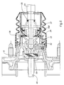
- FIG. 1 and 2 we can see a first example of a first embodiment of a servomotor according to the present invention with a longitudinal axis X comprising a envelope 2 defining a sealed volume in which is slidably mounted a skirt 4 provided with a central orifice 6 in which is mounted in a sealed manner a piston 8.
- the skirt divides the sealed volume into a first chamber before low pressure 10 and a second rear chamber 12 with variable pressure.
- the first one chamber 10 is supplied for example with low pressure pneumatic fluid by a vacuum pump or the air intake of an engine.
- the pneumatic piston 8 is formed by a body 14 of substantially frustoconical shape oriented towards the rear, the base of the truncated cone being fixed in the central opening 6 of the skirt 4.
- the body 14 also has a substantially cylindrical tail extending rearward.
- the piston body 14 is pierced with an axial passage 18 through which is mounted a three-way valve 20 actuated by a control rod 22 connected to a first longitudinal end to a brake pedal (not shown).
- the three-way valve 20 comprises a first balancing valve 23 placing in communication at rest the front chamber 10 and the rear chamber 12, and a second valve 24 for admission of the air at atmospheric pressure into the rear chamber in the phase of braking.
- the first 23 and the second 24 valves respectively comprise first and second seats 26, 28 respectively carried by the piston body 14 and by a first longitudinal end 30 of a plunger 32 mounted at a second axial end 34 of the stem. order 22.
- the rear end 30 of the plunger 32 rotulously receives the front end 34 of the control rod and extends backwards by frustoconical expansion facing forward.
- the plunger assembly 32 and control rod 22 form a brake control 33
- Each valve 22, 24 also includes a shutter 36 secured to the piston body having an annular plate 38 adapted to bear against the first seat 26 or the second seat 28 or both 26,28 simultaneously in equilibrium position.
- a cylindrical spring 35 confirming the application of the shutter 36 on the first and / or second seats 26,28 is mounted in reaction against a fixed element 37 of the body of piston and a rear face 40 of the plate 38 shutter.
- the plunger 32 is slidably mounted in a front portion of smaller diameter passage 18 passing through the piston body 18.
- the servomotor also comprises a push rod 48 coaxial with the rod of control 22 and mounted between the plunger and a master cylinder (not shown).
- the stem 48 comprises at a first longitudinal end 50 rear housing 52 in the form of cup receiving a reaction disc 55 next to a second longitudinal end 54 before the plunger 32, called probe and a front end of the pneumatic piston.
- the push rod 48 transmits to the master cylinder the forces applied to the rod of command 22 and by the pneumatic piston driven by the skirt 4.
- the reaction disc 55 is made of substantially incompressible material and the forces provided by the control rod, the pneumatic piston and the thrust rod transmitting the reaction of the master cylinder.
- the plunger 32 has at least a first cylindrical portion 44 adapted to be climb with a minimum clearance to avoid jamming in a first section cylindrical 42 of the front portion of the passage 18 ensuring the guidance of the plunger in the piston body, the first cylindrical portion 44 bearing the probe 54.
- the plunger also has a second cylindrical portion 58 in before frustoconical blooming and larger diameter compared to diameter of the first cylindrical portion 44 and mounted also with a minimum clearance in a second cylindrical section 60 of the passage 18 of the piston body 14.
- the servomotor also comprises a first return spring 62 of the piston in rest position and mounted in compression between the piston and an inner face of the casing 2, and a second return spring 64 of the control rod mounted in compression between an annular surface 66 projecting from the surface of the stem of control 22 and the fixed member 37 of the piston.
- the booster according to the present invention also comprises means 68 for damping the relative and especially oscillatory movement between the braking control 33 and the pneumatic piston 8.
- the means 68 perform a friction coupling between the plunger 32 and the piston 8 to reduce the amplitude of the oscillating movements of the piston relative to the plunger 32.
- the means 68 comprise an annular element 72 in material with a high coefficient of friction, mounted in an annular groove 70 made on the outer surface of the second cylindrical portion 58 of the plunger 32.
- the dimensions of the seal 72 and the groove 70 are determined so as to ensure an effort sufficient friction between the surface of the seal 72 and the second cylindrical section 60 passage 18 to sufficiently mitigate the oscillatory movements between the piston and probe and avoid or at least reduce the noise of "wiper noise".
- the annular element is for example made of elastomer, for example rubber.
- the annular element is advantageously an O-ring, which is of a low price of very easy installation and long service life.
- FIG. 3 a second exemplary embodiment of the first embodiment of FIG. embodiment in which means means damping relative movement between the plunger and the pneumatic piston are carried by the piston 8.
- the piston 8 has a groove 74 formed in the inner surface of the second section cylindrical 60 of the passage 18 in which is mounted an O-ring 72, and in contact with the second cylindrical portion 58.
- FIG. 4 a third exemplary embodiment of the first embodiment of FIG. embodiment in which the O-ring is mounted in a groove 170 made in the first cylindrical portion 44 of the plunger, the seal then coming into contact with the surface interior of the first cylindrical section 42.
- the vibration frequency of the piston 8 report to probe 32 is typically of the order of 50 Hertz. Friction efforts which are necessary for this vibration frequency between the plunger 32 and the piston 8, are advantageously between 5 and 40 Newtons, preferably between 5 and 20 Newtons and more preferably between 10 and 20 Newtons.
- seals quadrilobes or lip seal it is possible to envisage having several joints if the oscillations require it, for example a first joint at the level of the first cylindrical part and a second seal at the level of the second part cylindrical of the diver.
- means 68 including elements material with a high coefficient of friction angularly distributed over the the periphery of the plunger or in the passage 18. These elements are for example overmolded with the piston typically made by molding.
- FIG. 5 a second embodiment of a servomotor can be seen according to FIG. present invention comprising damping means 168 relative movement between the brake control 33 and the pneumatic piston 8.
- the means 168 are attached to a rear face of the shutter plate 38 of the valve three. lanes 20 and to the fixed element 37 of the pneumatic piston 8.
- the operation of the booster according to the present invention is as follows: moving the brake control 33 towards the push rod 48 the Pneumatic piston 8 is carried away by the pressure difference between the front chamber 10 and the rear chamber 12, the shutter plate 38 comes into contact with the first seat 26 and closes the balancing valve 23 and moves away from the second seat 24 and opens the intake valve 28.
- the pneumatic piston 8 moves in the first direction F1 with too much speed, the shutter plate 38 remains in contact with the first seat 26 and maintaining the balancing valve 23 closed as long as the first seat 26 is axially behind the second seat 28.
- the shutter plate 38 comes into application of the second seat 28 and moves away from the first seat 26.
- the displacement of the shutter plate 38 is then determined by the position of the plunger 32 or the brake control 33. Gold because of the presence of the means 168 between the plate shutter 38 and the piston 8, the movement of the piston 8 relative to the control of braking 33 is damped in the direction F1 by means of the shutter plate 38. Then the piston 8 moves in the direction F2, the first seat 26 carried by the piston 8 again comes into contact with the shutter plate 38 and tends to want to push it back in the direction F2, and to open the inlet valve 24, the movement of the plate shutter 38 is also damped by the means 168 in the direction F2, the oscillatory movement of the piston 8 relative to the brake control 33 is amortized.
- FIG. 6 a third embodiment of a servomotor can be seen according to FIG. the present invention in which damping means 268 are arranged on the pneumatic piston 8 and the control rod 22.
- the means 168 are fixed by a first end to the fixed element of the piston pneumatic and the annular bearing surface 66 of the second return spring 64 of the control rod 22.
- FIG. 7 a fourth embodiment can be seen according to the present invention in which the damping means 368,468 are of the magnetic type.
- the plunger 32 has on the outer wall of the first cylindrical portion 44 a first magnet 302 and the pneumatic piston 8 has on the inner wall of the first cylindrical section 42 of the passage 18 of the piston a second magnet 304 substantially facing the first magnet 302, each first and second magnets 302,304 being oriented so that poles first and second magnets opposite are opposed so that the field appearing magnet opposes the relative distance of the plunger and piston.
- first and second magnets 302, 304 are advantageously of annular shape and are mounted in first and second grooves 306, 308 made respectively in the first cylindrical portion 44 of the plunger 32 and the cylindrical section 42 of the passage 18 of the piston 8.
- the annular shape of the magnets 302,304 makes it possible to dispense with an angular orientation of the plunger 32 with respect to the piston 8 during assembly.
- first and second magnets angularly distributed on the surface of the plunger 32 and the passage 18 of the piston 8 can be provided.
- the second magnet is advantageously overmolded in the pneumatic piston which is typically made by plastic molding.
- the magnets are permanent magnet type, electric magnet or electro magnet. In these latter cases, it is then advantageously possible to achieve an active system to create a damping effect of the relative movement of the piston relative to the plunger only in the phase likely to appear the noise of "wiper noise".
- a calculator generates a stop command of the power supply from one to the other of the magnets beyond a certain pressure hydraulic in the master cylinder characterizing the fact that a reaction in the direction F2 is applied to the pneumatic piston and the brake control via the rear face of the reaction disc, eliminating parasitic relative movements between the piston and brake control.
- electromagnetic means can be arranged in any another place for coupling the pneumatic piston and the brake control.
- the piston and at least one element of the braking control are loaded at least locally with electrostatic charges of opposing loads creating an attraction between the piston and the brake control.
- the electrostatically charged areas are facing each other or at least able to overlap at least partially.
- depreciation means are not necessarily bidirectional and that it is conceivable to provide for depreciation only in the F1 direction or in the F2 direction, which would nevertheless produce a significant noise reduction of "wiper noise",
- damping means having an effect temporary, only in the braking start phase is not outside the scope of the present invention
- the booster according to the present invention can also other means to avoid the noise of "wiper noise", for example a diver comprising a probe provided with an axial protrusion intended to come into permanence in contact with the rear face of the reaction disk and a disk housing reaction allowing a clearance between the front face of the reaction disk and the bottom of the housing to determine the jump.
- a diver comprising a probe provided with an axial protrusion intended to come into permanence in contact with the rear face of the reaction disk and a disk housing reaction allowing a clearance between the front face of the reaction disk and the bottom of the housing to determine the jump.
- the present invention applies mainly to the car braking industry special.
Landscapes
- Engineering & Computer Science (AREA)
- Transportation (AREA)
- Mechanical Engineering (AREA)
- Braking Systems And Boosters (AREA)
- Braking Arrangements (AREA)
- Vibration Prevention Devices (AREA)
Abstract
Description
Au repos, un jeu est prévu entre le disque de réaction et le plongeur, déterminant la phase de saut bien connue de l'homme du métier.
Cependant parfois, il peut arriver pour une vitesse déterminée de déplacement de la tige de commande et un effort appliqué à la tige de commande déterminé, que le piston pneumatique après fermeture du clapet d'équilibrage et ouverture du clapet d'admission, se déplace axialement vers la tige de poussée avec une vitesse suffisante pour provoquer la réouverture du clapet d'équilibrage et la fermeture du clapet d'admission. Le piston pneumatique est repoussé alors axialement vers la pédale, provoquant la fermeture du clapet d'équilibrage et l'ouverture du clapet d'admission. Cette séquence d'ouverture-fermeture des clapets a lieu plusieurs fois jusqu'à ce qu'une réaction apparaisse dans le maítre-cylindre et que le disque de réaction se déforme.
- La figure 1 est une vue en coupe longitudinale d'un premier exemple d'un premier mode de réalisation d'un servomoteur pneumatique selon la présente invention ;
- La figure 2 est une vue de détail de la figure 1 ;
- La figure 3 est une vue en coupe longitudinale d'un détail d'un deuxième exemple du premier mode de réalisation selon la présente invention ;
- La figure 4 est une vue en coupe longitudinale d'un détail d'un troisième exemple du premier mode de réalisation selon la présente invention ;
- La figure 5 est une vue en coupe longitudinale d'un détail d'un premier exemple d'un deuxième mode de réalisation selon la présente invention ;
- La figure 6 est une vue en coupe longitudinale d'un détail d'un deuxième exemple d'un deuxième mode de réalisation selon la présente invention ;
- La figure 7 est une vue en coupe longitudinale d'un cinquième mode de réalisation d'un servomoteur selon la présente invention.
Le premier 23 et le deuxième 24 clapets comportent respectivement des premier et deuxième sièges 26,28 portés respectivement par le corps de piston 14 et par une première extrémité longitudinale arrière 30 d'un plongeur 32 monté à une deuxième extrémité axiale 34 de la tige de commande 22.
Le deuxième aimant est avantageusement surmoulé dans le piston pneumatique qui est typiquement réalisé par moulage de matière plastique.
Claims (18)
- Servomoteur d'assistance pneumatique au freinage comportant une enveloppe (2) d'axe longitudinal (X), une première chambre à basse pression (10), une deuxième chambre à pression variable (12), une jupe (4) délimitant la première et la deuxième chambres (10,12) et montée à coulissement étanche dans l'enveloppe (2), un piston pneumatique (8) monté solidaire d'une partie centrale de la jupe (2), une valve trois voies (20) montée dans une queue (14) du piston pneumatique (8), et actionnée par une commande de freinage (33) comportant une tige de commande (22) d'axe longitudinal (X), entraínée par une pédale à une première extrémité longitudinale (25), un plongeur (32) monté de manière rotulante à une deuxième extrémité longitudinale (34) de ladite tige de commande (22), ladite valve trois voies (20) comportant un clapet d'équilibrage (23) apte à mettre en communication au repos la première et la deuxième chambres (10,12) et une clapet d'admission (24) apte à permettre l'alimentation en fluide pneumatique à haute pression de la deuxième chambre (12), le clapet d'équilibrage (23) comportant un premier siège (26) porté par le corps (14) du piston et un obturateur (36), le clapet d'admission (24) comportant un deuxième siège (28) porté par une première extrémité longitudinale du plongeur et ledit obturateur (36), le plongeur (32) comporte à une deuxième extrémité longitudinale opposée à la première extrémité (54) une surface en regard d'une première face d'un disque de réaction (55) en appui par une deuxième face sur une première extrémité longitudinale (50) d'une tige de poussée (48) apte à transmettre un effort de freinage appliqué à la commande de freinage et l'assistance de freinage à un maítre-cylindre, le piston pneumatique (8) comportant également dans sa partie centrale une surface en appui contre la première face du disque de réaction (55) caractérisé en ce que ledit servomoteur comporte des moyens (68,168,268,368,468) permettant d'amortir le mouvement relatif et notamment oscillatoire entre la commande de freinage et le piston pneumatique en l'absence de réaction hydraulique.
- Servomoteur d'assistance pneumatique au freinage selon la revendication 1 caractérisé en ce que lesdits moyens d'amortissement (68) réalisent un couplage par frottement entre la commande de freinage (33) et le piston pneumatique (8).
- Servomoteur d'assistance pneumatique au freinage selon la revendication 2 caractérisé en ce que lesdits moyens d'amortissement (68) sont interposés entre le plongeur (32) et le piston (8).
- Servomoteur d'assistance pneumatique au freinage selon la revendication 3 caractérisé en ce que lesdits moyens d'amortissement comportent une gorge annulaire (170) pratiquée dans une paroi extérieure d'une première partie cylindrique (44) du plongeur (32) proche de la tige de commande (22) et un élément en matériau (72) à fort coefficient de frottement monté dans ladite gorge (70) et destiné à venir en contact d'une première section cylindrique (42) du passage (18) du piston (8).
- Servomoteur d'assistance pneumatique au freinage selon la revendication 3 caractérisé en ce que lesdits moyens d'amortissement (68) comportent une gorge annulaire (74) pratiquée dans une paroi intérieure d'une deuxième section cylindrique (60) du passage (18) du piston (8) et un élément (72) en matériau à fort coefficient de frottement monté dans ladite gorge (74) et destiné à venir en contact d'une deuxième partie cylindrique (58) du plongeur proche de la tige de commande.
- Servomoteur d'assistance pneumatique au freinage selon la revendication 3 caractérisé en ce que lesdits moyens d'amortissement comportent une gorge annulaire (70) pratiquée dans une paroi extérieure d'une deuxième partie cylindrique (58) du plongeur proche du disque de réaction (55) et un élément (72) en matériau à fort coefficient de frottement monté dans ladite gorge (70) et destiné à venir en contact d'une deuxième section cylindrique (60) du passage (18) du piston (8).
- Servomoteur d'assistance pneumatique au freinage selon l'une quelconque des revendications 4 à 6 caractérisé en ce que ledit élément (72) est fabriqué en élastomère.
- Servomoteur d'assistance pneumatique au freinage selon la revendication précédente caractérisé en ce que ledit élément est un joint torique.
- Servomoteur d'assistance pneumatique au freinage selon l'une quelconque des revendications de 2 à 8 caractérisé en ce que les efforts de frottement entre le piston (8) et la commande de freinage sont compris de manière avantageuse entre 5 Newtons et 40 Newtons.
- Servomoteur d'assistance pneumatique au freinage selon la revendication précédente caractérisé en ce que les efforts de frottement entre le piston (8) et la commande de freinage sont compris de manière plus avantageuse entre 5 Newtons et 20 Newtons.
- Servomoteur d'assistance pneumatique au freinage selon la revendication précédente caractérisé en ce que les efforts de frottement entre le piston (8) et la commande de freinage sont compris de manière encore plus avantageuse entre 10 Newtons et 20 Newtons.
- Servomoteur d'assistance pneumatique au freinage selon la revendication 1 caractérisé en ce que lesdits moyens d'amortissement (168) relient par une première extrémité un élément fixe (37) du piston et par une deuxième extrémité une face arrière de l'obturateur (32).
- Servomoteur d'assistance pneumatique au freinage selon la revendication 1 caractérisé en ce que lesdits moyens d'amortissement (268) relient par une première extrémité un élément fixe (37) du piston (8) et par une deuxième extrémité la tige de commande (22).
- Servomoteur d'assistance pneumatique au freinage selon la revendication 1 caractérisé en ce que lesdits moyens d'amortissement (368,468) sont du type magnétiques.
- Servomoteur d'assistance pneumatique au freinage selon la revendication précédente caractérisé en ce que des premier (302) et deuxième (304) aimants sont montés respectivement sur la commande de freinage (33) et sur le piston pneumatique (8) de manière à ce que leurs pôles opposés soient en vis-à-vis ou au moins partiellement.
- Servomoteur d'assistance pneumatique au freinage selon la revendication précédente caractérisé en ce qu'au moins l'un desdits aimants (302,304) est un électroaimant et en ce qu'il est prévu d'arrêter l'alimentation électrique dudit électroaimant lorsque les risques de mouvements relatifs oscillatoires perturbateurs entre le piston et le plongeur ont disparus.
- Servomoteur d'assistance pneumatique au freinage selon la revendication 1 caractérisé en ce que lesdits moyens d'amortissement sont du type électrostatique.
- Servomoteur d'assistance pneumatique au freinage selon la revendication précédente caractérisé en ce que le piston et la commande de freinage sont au moins localement chargés par des charges électrostatiques opposées.
Priority Applications (1)
| Application Number | Priority Date | Filing Date | Title |
|---|---|---|---|
| PL04008298T PL1470980T3 (pl) | 2003-04-08 | 2004-04-06 | Pneumatyczny układ wspomagania parcy hamulca o nniskim poziomie hałasu |
Applications Claiming Priority (2)
| Application Number | Priority Date | Filing Date | Title |
|---|---|---|---|
| FR0304322 | 2003-04-08 | ||
| FR0304322A FR2853610B1 (fr) | 2003-04-08 | 2003-04-08 | Servomoteur d'assistance pneumatique au freinage a bruit de fonctionnement reduit |
Publications (2)
| Publication Number | Publication Date |
|---|---|
| EP1470980A1 true EP1470980A1 (fr) | 2004-10-27 |
| EP1470980B1 EP1470980B1 (fr) | 2006-10-11 |
Family
ID=32947348
Family Applications (1)
| Application Number | Title | Priority Date | Filing Date |
|---|---|---|---|
| EP04008298A Expired - Lifetime EP1470980B1 (fr) | 2003-04-08 | 2004-04-06 | Servomoteur d'assistance pneumatique au freinage à bruit de fonctionnement réduit |
Country Status (12)
| Country | Link |
|---|---|
| US (1) | US6976417B2 (fr) |
| EP (1) | EP1470980B1 (fr) |
| JP (1) | JP2004306949A (fr) |
| CN (1) | CN100377941C (fr) |
| AT (1) | ATE342186T1 (fr) |
| BR (1) | BRPI0401205B1 (fr) |
| DE (1) | DE602004002715T2 (fr) |
| ES (1) | ES2271729T3 (fr) |
| FR (1) | FR2853610B1 (fr) |
| PL (1) | PL1470980T3 (fr) |
| PT (1) | PT1470980E (fr) |
| RU (1) | RU2344950C2 (fr) |
Cited By (1)
| Publication number | Priority date | Publication date | Assignee | Title |
|---|---|---|---|---|
| WO2017158467A1 (fr) * | 2016-03-15 | 2017-09-21 | ローベルト ボッシュ ゲゼルシャフト ミット ベシュレンクテル ハフツング | Dispositif d'amplification de force de freinage |
Families Citing this family (5)
| Publication number | Priority date | Publication date | Assignee | Title |
|---|---|---|---|---|
| DE102006016545B3 (de) * | 2006-04-07 | 2007-05-16 | Lucas Automotive Gmbh | Bremskraftverstärkungseinrichtung mit Dämpfungselement |
| DE102010034828A1 (de) | 2010-08-19 | 2012-02-23 | Lucas Automotive Gmbh | Unterdruckbremskraftverstärker mit reduzierter Geräuschemission und Verfahren zum Herstellen eines solchen Unterdruckbremskraftverstärkers |
| JP5758374B2 (ja) * | 2012-12-27 | 2015-08-05 | 日信工業株式会社 | 負圧ブースタ |
| JP2014196030A (ja) * | 2013-03-29 | 2014-10-16 | 株式会社アドヴィックス | 負圧式倍力装置 |
| RU2643013C2 (ru) * | 2016-01-21 | 2018-01-29 | Федеральное государственное бюджетное образовательное учреждение высшего образования "Омский государственный технический университет" | Способ управления работой гидравлической тормозной системы транспортного средства и устройство для его осуществления |
Citations (3)
| Publication number | Priority date | Publication date | Assignee | Title |
|---|---|---|---|---|
| FR2809068A1 (fr) * | 2000-05-19 | 2001-11-23 | Bosch Gmbh Robert | Logement de reception d'un disque de reaction et servomoteur pneumatique d'assistance au freinage comportant un tel logement |
| US6352015B1 (en) * | 1999-09-10 | 2002-03-05 | Bosch Braking Systems Co., Ltd. | Booster |
| WO2002047952A1 (fr) * | 2000-12-14 | 2002-06-20 | Robert Bosch Gmbh | Dispositif de freinage assiste a valve d'urgence avec saut eleve |
Family Cites Families (10)
| Publication number | Priority date | Publication date | Assignee | Title |
|---|---|---|---|---|
| ES480732A2 (es) * | 1978-05-20 | 1980-07-01 | Girling Ltd | Servo-amplificador de fuerza para sistema de frenos de vehi-culo. |
| JPS6192949A (ja) * | 1984-10-12 | 1986-05-10 | Nippon Air Brake Co Ltd | 気圧式倍力装置 |
| SU1449409A1 (ru) * | 1987-05-13 | 1989-01-07 | Винницкий Проектно-Конструкторский Технологический Институт Гидроагрегатов | Пневматический усилитель |
| JPH01182648A (ja) * | 1988-01-08 | 1989-07-20 | Toshiba Corp | 回転機械の軸方向吸振装置 |
| JPH0284033U (fr) * | 1988-12-19 | 1990-06-29 | ||
| FR2675447A1 (fr) * | 1991-04-17 | 1992-10-23 | Bendix Europ Service Tech | Servomoteur pneumatique. |
| JP2904231B2 (ja) * | 1991-07-12 | 1999-06-14 | 自動車機器株式会社 | 倍力装置 |
| FR2695896B1 (fr) * | 1992-09-21 | 1994-12-02 | Alliedsignal Europ Services | Servomoteur pneumatique. |
| FR2724356B1 (fr) * | 1994-09-08 | 1997-01-10 | Alliedsignal Europ Services | Servomoteur pneumatique d'assistance au freinage |
| FR2817219B1 (fr) * | 2000-11-29 | 2003-01-10 | Bosch Gmbh Robert | Servofrein pneumatique a vibrations reduites |
-
2003
- 2003-04-08 FR FR0304322A patent/FR2853610B1/fr not_active Expired - Fee Related
-
2004
- 2004-04-06 PT PT04008298T patent/PT1470980E/pt unknown
- 2004-04-06 EP EP04008298A patent/EP1470980B1/fr not_active Expired - Lifetime
- 2004-04-06 PL PL04008298T patent/PL1470980T3/pl unknown
- 2004-04-06 DE DE602004002715T patent/DE602004002715T2/de not_active Expired - Lifetime
- 2004-04-06 AT AT04008298T patent/ATE342186T1/de active
- 2004-04-06 ES ES04008298T patent/ES2271729T3/es not_active Expired - Lifetime
- 2004-04-07 RU RU2004110385/11A patent/RU2344950C2/ru not_active IP Right Cessation
- 2004-04-08 BR BRPI0401205A patent/BRPI0401205B1/pt not_active IP Right Cessation
- 2004-04-08 CN CNB2004100451445A patent/CN100377941C/zh not_active Expired - Lifetime
- 2004-04-08 JP JP2004114053A patent/JP2004306949A/ja active Pending
- 2004-04-26 US US10/832,018 patent/US6976417B2/en not_active Expired - Lifetime
Patent Citations (3)
| Publication number | Priority date | Publication date | Assignee | Title |
|---|---|---|---|---|
| US6352015B1 (en) * | 1999-09-10 | 2002-03-05 | Bosch Braking Systems Co., Ltd. | Booster |
| FR2809068A1 (fr) * | 2000-05-19 | 2001-11-23 | Bosch Gmbh Robert | Logement de reception d'un disque de reaction et servomoteur pneumatique d'assistance au freinage comportant un tel logement |
| WO2002047952A1 (fr) * | 2000-12-14 | 2002-06-20 | Robert Bosch Gmbh | Dispositif de freinage assiste a valve d'urgence avec saut eleve |
Cited By (4)
| Publication number | Priority date | Publication date | Assignee | Title |
|---|---|---|---|---|
| WO2017158467A1 (fr) * | 2016-03-15 | 2017-09-21 | ローベルト ボッシュ ゲゼルシャフト ミット ベシュレンクテル ハフツング | Dispositif d'amplification de force de freinage |
| CN108778870A (zh) * | 2016-03-15 | 2018-11-09 | 罗伯特·博世有限公司 | 刹车力的增倍装置 |
| CN108778870B (zh) * | 2016-03-15 | 2021-02-05 | 罗伯特·博世有限公司 | 刹车力的增倍装置 |
| US11040707B2 (en) | 2016-03-15 | 2021-06-22 | Robert Bosch Gmbh | Booster of braking force |
Also Published As
| Publication number | Publication date |
|---|---|
| BRPI0401205A (pt) | 2004-11-30 |
| ATE342186T1 (de) | 2006-11-15 |
| FR2853610A1 (fr) | 2004-10-15 |
| EP1470980B1 (fr) | 2006-10-11 |
| CN1537764A (zh) | 2004-10-20 |
| PT1470980E (pt) | 2007-01-31 |
| JP2004306949A (ja) | 2004-11-04 |
| RU2344950C2 (ru) | 2009-01-27 |
| PL1470980T3 (pl) | 2007-03-30 |
| RU2004110385A (ru) | 2005-10-20 |
| FR2853610B1 (fr) | 2006-04-28 |
| US6976417B2 (en) | 2005-12-20 |
| ES2271729T3 (es) | 2007-04-16 |
| US20040206230A1 (en) | 2004-10-21 |
| DE602004002715D1 (de) | 2006-11-23 |
| DE602004002715T2 (de) | 2007-08-16 |
| BRPI0401205B1 (pt) | 2015-10-20 |
| CN100377941C (zh) | 2008-04-02 |
Similar Documents
| Publication | Publication Date | Title |
|---|---|---|
| FR2751602A1 (fr) | Dispositif de freinage assiste a rapport d'assistance variable | |
| EP1470980B1 (fr) | Servomoteur d'assistance pneumatique au freinage à bruit de fonctionnement réduit | |
| EP0613431B1 (fr) | Servomoteur pneumatique | |
| EP0368691B1 (fr) | Dispositif de commande d'un servomoteur d'assistance, notamment pour système de freinage de véhicule automobile | |
| EP1397279A1 (fr) | Servomoteur a deux sauts differencies fixe et variable | |
| EP1351850B1 (fr) | Dispositif de freinage assiste a valve d'urgence avec saut eleve | |
| FR2809066A1 (fr) | Servomoteur comportant un embrayage unidirectionnel expansible | |
| EP0796189B1 (fr) | Servomoteur pneumatique d'assistance au freinage, a fonctionnement silencieux | |
| EP1339584B1 (fr) | Dispositif de freinage assiste, a fonctionnement ameliore, pour vehicule a moteur. | |
| EP1102695B1 (fr) | Maitre-cylindre a reaction hydraulique evolutive en pression | |
| EP1325853B1 (fr) | Servomoteur d'assistance pneumatique au freinage à embrayage unidirectionnel et à réaction réduite | |
| WO2002094626A1 (fr) | Servomoteur d'assistance pneumatique au freinage a hauteur de saut variable | |
| EP1436182B1 (fr) | Maitre-cylindre perfectionne pour systeme de freinage | |
| WO1998022321A1 (fr) | Systeme de feinage assiste a reaction hydraulique amelioree | |
| FR2841617A1 (fr) | Systeme de pilotage d'un embrayage | |
| FR2822427A1 (fr) | Servomoteur d'assistance a ecoulement simplifie | |
| EP1216907A1 (fr) | Systèm de commande de freinage amélioré muni d'un servomoteur d'assistance et d'une réaction hydraulique. | |
| FR2829453A1 (fr) | Servomoteur d'assistance de freinage | |
| FR2794091A1 (fr) | Amplificateur de freinage a depression perfectionne | |
| FR2778616A1 (fr) | Maitre-cylindre a reaction hydraulique independante de la viscosite | |
| EP0991556A1 (fr) | Servomoteur pneumatique d'assistance au freinage a clapet perfectionne | |
| FR2864506A1 (fr) | Servomoteur a saut variable progressif | |
| FR2902735A1 (fr) | Amplificateur de freinage | |
| FR2905653A1 (fr) | Servomoteur pneumatique comportant une soupape de reequilibrage. | |
| FR2872762A1 (fr) | Disque de reaction possedant une surepaisseur d'etancheite pour servomoteur d'assistance de freinage |
Legal Events
| Date | Code | Title | Description |
|---|---|---|---|
| PUAI | Public reference made under article 153(3) epc to a published international application that has entered the european phase |
Free format text: ORIGINAL CODE: 0009012 |
|
| AK | Designated contracting states |
Kind code of ref document: A1 Designated state(s): AT BE BG CH CY CZ DE DK EE ES FI FR GB GR HU IE IT LI LU MC NL PL PT RO SE SI SK TR |
|
| AX | Request for extension of the european patent |
Extension state: AL HR LT LV MK |
|
| 17P | Request for examination filed |
Effective date: 20050427 |
|
| AKX | Designation fees paid |
Designated state(s): AT BE BG CH CY CZ DE DK EE ES FI FR GB GR HU IE IT LI LU MC NL PL PT RO SE SI SK TR |
|
| GRAP | Despatch of communication of intention to grant a patent |
Free format text: ORIGINAL CODE: EPIDOSNIGR1 |
|
| GRAC | Information related to communication of intention to grant a patent modified |
Free format text: ORIGINAL CODE: EPIDOSCIGR1 |
|
| GRAS | Grant fee paid |
Free format text: ORIGINAL CODE: EPIDOSNIGR3 |
|
| GRAA | (expected) grant |
Free format text: ORIGINAL CODE: 0009210 |
|
| AK | Designated contracting states |
Kind code of ref document: B1 Designated state(s): AT BE BG CH CY CZ DE DK EE ES FI FR GB GR HU IE IT LI LU MC NL PL PT RO SE SI SK TR |
|
| PG25 | Lapsed in a contracting state [announced via postgrant information from national office to epo] |
Ref country code: SK Free format text: LAPSE BECAUSE OF FAILURE TO SUBMIT A TRANSLATION OF THE DESCRIPTION OR TO PAY THE FEE WITHIN THE PRESCRIBED TIME-LIMIT Effective date: 20061011 Ref country code: SI Free format text: LAPSE BECAUSE OF FAILURE TO SUBMIT A TRANSLATION OF THE DESCRIPTION OR TO PAY THE FEE WITHIN THE PRESCRIBED TIME-LIMIT Effective date: 20061011 Ref country code: FI Free format text: LAPSE BECAUSE OF FAILURE TO SUBMIT A TRANSLATION OF THE DESCRIPTION OR TO PAY THE FEE WITHIN THE PRESCRIBED TIME-LIMIT Effective date: 20061011 Ref country code: IE Free format text: LAPSE BECAUSE OF FAILURE TO SUBMIT A TRANSLATION OF THE DESCRIPTION OR TO PAY THE FEE WITHIN THE PRESCRIBED TIME-LIMIT Effective date: 20061011 Ref country code: IT Free format text: LAPSE BECAUSE OF FAILURE TO SUBMIT A TRANSLATION OF THE DESCRIPTION OR TO PAY THE FEE WITHIN THE PRESCRIBED TIME-LIMIT;WARNING: LAPSES OF ITALIAN PATENTS WITH EFFECTIVE DATE BEFORE 2007 MAY HAVE OCCURRED AT ANY TIME BEFORE 2007. THE CORRECT EFFECTIVE DATE MAY BE DIFFERENT FROM THE ONE RECORDED. Effective date: 20061011 |
|
| REG | Reference to a national code |
Ref country code: GB Ref legal event code: FG4D Free format text: NOT ENGLISH |
|
| REG | Reference to a national code |
Ref country code: CH Ref legal event code: EP |
|
| REG | Reference to a national code |
Ref country code: IE Ref legal event code: FG4D Free format text: LANGUAGE OF EP DOCUMENT: FRENCH |
|
| REF | Corresponds to: |
Ref document number: 602004002715 Country of ref document: DE Date of ref document: 20061123 Kind code of ref document: P |
|
| REG | Reference to a national code |
Ref country code: RO Ref legal event code: EPE |
|
| GBT | Gb: translation of ep patent filed (gb section 77(6)(a)/1977) |
Effective date: 20061129 |
|
| REG | Reference to a national code |
Ref country code: SE Ref legal event code: TRGR |
|
| PG25 | Lapsed in a contracting state [announced via postgrant information from national office to epo] |
Ref country code: DK Free format text: LAPSE BECAUSE OF FAILURE TO SUBMIT A TRANSLATION OF THE DESCRIPTION OR TO PAY THE FEE WITHIN THE PRESCRIBED TIME-LIMIT Effective date: 20070111 Ref country code: BG Free format text: LAPSE BECAUSE OF FAILURE TO SUBMIT A TRANSLATION OF THE DESCRIPTION OR TO PAY THE FEE WITHIN THE PRESCRIBED TIME-LIMIT Effective date: 20070111 |
|
| REG | Reference to a national code |
Ref country code: PT Ref legal event code: SC4A Free format text: AVAILABILITY OF NATIONAL TRANSLATION Effective date: 20061121 |
|
| REG | Reference to a national code |
Ref country code: SE Ref legal event code: RPOT |
|
| REG | Reference to a national code |
Ref country code: PL Ref legal event code: T3 |
|
| REG | Reference to a national code |
Ref country code: ES Ref legal event code: FG2A Ref document number: 2271729 Country of ref document: ES Kind code of ref document: T3 |
|
| REG | Reference to a national code |
Ref country code: IE Ref legal event code: FD4D |
|
| PLBE | No opposition filed within time limit |
Free format text: ORIGINAL CODE: 0009261 |
|
| STAA | Information on the status of an ep patent application or granted ep patent |
Free format text: STATUS: NO OPPOSITION FILED WITHIN TIME LIMIT |
|
| 26N | No opposition filed |
Effective date: 20070712 |
|
| PG25 | Lapsed in a contracting state [announced via postgrant information from national office to epo] |
Ref country code: GR Free format text: LAPSE BECAUSE OF FAILURE TO SUBMIT A TRANSLATION OF THE DESCRIPTION OR TO PAY THE FEE WITHIN THE PRESCRIBED TIME-LIMIT Effective date: 20070112 |
|
| PGRI | Patent reinstated in contracting state [announced from national office to epo] |
Ref country code: IT Effective date: 20080601 |
|
| PG25 | Lapsed in a contracting state [announced via postgrant information from national office to epo] |
Ref country code: EE Free format text: LAPSE BECAUSE OF FAILURE TO SUBMIT A TRANSLATION OF THE DESCRIPTION OR TO PAY THE FEE WITHIN THE PRESCRIBED TIME-LIMIT Effective date: 20061011 |
|
| PG25 | Lapsed in a contracting state [announced via postgrant information from national office to epo] |
Ref country code: MC Free format text: LAPSE BECAUSE OF NON-PAYMENT OF DUE FEES Effective date: 20070430 |
|
| PG25 | Lapsed in a contracting state [announced via postgrant information from national office to epo] |
Ref country code: LU Free format text: LAPSE BECAUSE OF NON-PAYMENT OF DUE FEES Effective date: 20070406 Ref country code: CY Free format text: LAPSE BECAUSE OF FAILURE TO SUBMIT A TRANSLATION OF THE DESCRIPTION OR TO PAY THE FEE WITHIN THE PRESCRIBED TIME-LIMIT Effective date: 20061011 |
|
| PG25 | Lapsed in a contracting state [announced via postgrant information from national office to epo] |
Ref country code: HU Free format text: LAPSE BECAUSE OF FAILURE TO SUBMIT A TRANSLATION OF THE DESCRIPTION OR TO PAY THE FEE WITHIN THE PRESCRIBED TIME-LIMIT Effective date: 20070412 |
|
| REG | Reference to a national code |
Ref country code: FR Ref legal event code: PLFP Year of fee payment: 13 |
|
| PGFP | Annual fee paid to national office [announced via postgrant information from national office to epo] |
Ref country code: TR Payment date: 20160329 Year of fee payment: 13 |
|
| PGFP | Annual fee paid to national office [announced via postgrant information from national office to epo] |
Ref country code: RO Payment date: 20160330 Year of fee payment: 13 Ref country code: PT Payment date: 20160328 Year of fee payment: 13 |
|
| PGFP | Annual fee paid to national office [announced via postgrant information from national office to epo] |
Ref country code: NL Payment date: 20160422 Year of fee payment: 13 |
|
| PGFP | Annual fee paid to national office [announced via postgrant information from national office to epo] |
Ref country code: CH Payment date: 20160422 Year of fee payment: 13 |
|
| PGFP | Annual fee paid to national office [announced via postgrant information from national office to epo] |
Ref country code: IT Payment date: 20160422 Year of fee payment: 13 Ref country code: BE Payment date: 20160422 Year of fee payment: 13 Ref country code: AT Payment date: 20160420 Year of fee payment: 13 |
|
| REG | Reference to a national code |
Ref country code: FR Ref legal event code: PLFP Year of fee payment: 14 |
|
| PGFP | Annual fee paid to national office [announced via postgrant information from national office to epo] |
Ref country code: CZ Payment date: 20170328 Year of fee payment: 14 Ref country code: PL Payment date: 20170324 Year of fee payment: 14 |
|
| PGFP | Annual fee paid to national office [announced via postgrant information from national office to epo] |
Ref country code: FR Payment date: 20170424 Year of fee payment: 14 Ref country code: GB Payment date: 20170425 Year of fee payment: 14 |
|
| PGFP | Annual fee paid to national office [announced via postgrant information from national office to epo] |
Ref country code: SE Payment date: 20170425 Year of fee payment: 14 Ref country code: ES Payment date: 20170503 Year of fee payment: 14 |
|
| REG | Reference to a national code |
Ref country code: CH Ref legal event code: PL |
|
| REG | Reference to a national code |
Ref country code: NL Ref legal event code: MM Effective date: 20170501 |
|
| REG | Reference to a national code |
Ref country code: AT Ref legal event code: MM01 Ref document number: 342186 Country of ref document: AT Kind code of ref document: T Effective date: 20170406 |
|
| PG25 | Lapsed in a contracting state [announced via postgrant information from national office to epo] |
Ref country code: RO Free format text: LAPSE BECAUSE OF NON-PAYMENT OF DUE FEES Effective date: 20170406 Ref country code: AT Free format text: LAPSE BECAUSE OF NON-PAYMENT OF DUE FEES Effective date: 20170406 Ref country code: NL Free format text: LAPSE BECAUSE OF NON-PAYMENT OF DUE FEES Effective date: 20170501 |
|
| PG25 | Lapsed in a contracting state [announced via postgrant information from national office to epo] |
Ref country code: CH Free format text: LAPSE BECAUSE OF NON-PAYMENT OF DUE FEES Effective date: 20170430 Ref country code: PT Free format text: LAPSE BECAUSE OF NON-PAYMENT OF DUE FEES Effective date: 20171006 Ref country code: LI Free format text: LAPSE BECAUSE OF NON-PAYMENT OF DUE FEES Effective date: 20170430 |
|
| REG | Reference to a national code |
Ref country code: BE Ref legal event code: MM Effective date: 20170430 |
|
| PG25 | Lapsed in a contracting state [announced via postgrant information from national office to epo] |
Ref country code: BE Free format text: LAPSE BECAUSE OF NON-PAYMENT OF DUE FEES Effective date: 20170430 Ref country code: IT Free format text: LAPSE BECAUSE OF FAILURE TO SUBMIT A TRANSLATION OF THE DESCRIPTION OR TO PAY THE FEE WITHIN THE PRESCRIBED TIME-LIMIT Effective date: 20170406 |
|
| PG25 | Lapsed in a contracting state [announced via postgrant information from national office to epo] |
Ref country code: CZ Free format text: LAPSE BECAUSE OF NON-PAYMENT OF DUE FEES Effective date: 20180406 |
|
| REG | Reference to a national code |
Ref country code: SE Ref legal event code: EUG |
|
| GBPC | Gb: european patent ceased through non-payment of renewal fee |
Effective date: 20180406 |
|
| PG25 | Lapsed in a contracting state [announced via postgrant information from national office to epo] |
Ref country code: SE Free format text: LAPSE BECAUSE OF NON-PAYMENT OF DUE FEES Effective date: 20180407 |
|
| PG25 | Lapsed in a contracting state [announced via postgrant information from national office to epo] |
Ref country code: GB Free format text: LAPSE BECAUSE OF NON-PAYMENT OF DUE FEES Effective date: 20180406 |
|
| PG25 | Lapsed in a contracting state [announced via postgrant information from national office to epo] |
Ref country code: FR Free format text: LAPSE BECAUSE OF NON-PAYMENT OF DUE FEES Effective date: 20180430 |
|
| REG | Reference to a national code |
Ref country code: ES Ref legal event code: FD2A Effective date: 20190911 |
|
| PG25 | Lapsed in a contracting state [announced via postgrant information from national office to epo] |
Ref country code: ES Free format text: LAPSE BECAUSE OF NON-PAYMENT OF DUE FEES Effective date: 20180407 |
|
| PG25 | Lapsed in a contracting state [announced via postgrant information from national office to epo] |
Ref country code: PL Free format text: LAPSE BECAUSE OF NON-PAYMENT OF DUE FEES Effective date: 20180406 |
|
| PG25 | Lapsed in a contracting state [announced via postgrant information from national office to epo] |
Ref country code: TR Free format text: LAPSE BECAUSE OF NON-PAYMENT OF DUE FEES Effective date: 20170406 |
|
| PGFP | Annual fee paid to national office [announced via postgrant information from national office to epo] |
Ref country code: DE Payment date: 20230627 Year of fee payment: 20 |
|
| REG | Reference to a national code |
Ref country code: DE Ref legal event code: R071 Ref document number: 602004002715 Country of ref document: DE |