EP1471040A1 - Procede et dispositif de fabrication de tube de verre - Google Patents
Procede et dispositif de fabrication de tube de verre Download PDFInfo
- Publication number
- EP1471040A1 EP1471040A1 EP03703074A EP03703074A EP1471040A1 EP 1471040 A1 EP1471040 A1 EP 1471040A1 EP 03703074 A EP03703074 A EP 03703074A EP 03703074 A EP03703074 A EP 03703074A EP 1471040 A1 EP1471040 A1 EP 1471040A1
- Authority
- EP
- European Patent Office
- Prior art keywords
- glass
- glass tube
- glass material
- piercing plug
- pressure
- Prior art date
- Legal status (The legal status is an assumption and is not a legal conclusion. Google has not performed a legal analysis and makes no representation as to the accuracy of the status listed.)
- Withdrawn
Links
Images





Classifications
-
- C—CHEMISTRY; METALLURGY
- C03—GLASS; MINERAL OR SLAG WOOL
- C03B—MANUFACTURE, SHAPING, OR SUPPLEMENTARY PROCESSES
- C03B37/00—Manufacture or treatment of flakes, fibres, or filaments from softened glass, minerals, or slags
- C03B37/01—Manufacture of glass fibres or filaments
- C03B37/012—Manufacture of preforms for drawing fibres or filaments
- C03B37/01205—Manufacture of preforms for drawing fibres or filaments starting from tubes, rods, fibres or filaments
- C03B37/01225—Means for changing or stabilising the shape, e.g. diameter, of tubes or rods in general, e.g. collapsing
- C03B37/01254—Means for changing or stabilising the shape, e.g. diameter, of tubes or rods in general, e.g. collapsing by expanding radially, e.g. by forcing a mandrel through or axial pressing a tube or rod
-
- C—CHEMISTRY; METALLURGY
- C03—GLASS; MINERAL OR SLAG WOOL
- C03B—MANUFACTURE, SHAPING, OR SUPPLEMENTARY PROCESSES
- C03B19/00—Other methods of shaping glass
- C03B19/14—Other methods of shaping glass by gas- or vapour- phase reaction processes
- C03B19/1469—Means for changing or stabilising the shape or form of the shaped article or deposit
-
- C—CHEMISTRY; METALLURGY
- C03—GLASS; MINERAL OR SLAG WOOL
- C03B—MANUFACTURE, SHAPING, OR SUPPLEMENTARY PROCESSES
- C03B23/00—Re-forming shaped glass
- C03B23/04—Re-forming tubes or rods
- C03B23/045—Tools or apparatus specially adapted for re-forming tubes or rods in general, e.g. glass lathes, chucks
-
- C—CHEMISTRY; METALLURGY
- C03—GLASS; MINERAL OR SLAG WOOL
- C03B—MANUFACTURE, SHAPING, OR SUPPLEMENTARY PROCESSES
- C03B23/00—Re-forming shaped glass
- C03B23/04—Re-forming tubes or rods
- C03B23/049—Re-forming tubes or rods by pressing
- C03B23/0493—Re-forming tubes or rods by pressing in a longitudinal direction, e.g. for upsetting or extrusion
-
- C—CHEMISTRY; METALLURGY
- C03—GLASS; MINERAL OR SLAG WOOL
- C03B—MANUFACTURE, SHAPING, OR SUPPLEMENTARY PROCESSES
- C03B23/00—Re-forming shaped glass
- C03B23/04—Re-forming tubes or rods
- C03B23/049—Re-forming tubes or rods by pressing
- C03B23/0496—Re-forming tubes or rods by pressing for expanding in a radial way, e.g. by forcing a mandrel through a tube or rod
-
- Y—GENERAL TAGGING OF NEW TECHNOLOGICAL DEVELOPMENTS; GENERAL TAGGING OF CROSS-SECTIONAL TECHNOLOGIES SPANNING OVER SEVERAL SECTIONS OF THE IPC; TECHNICAL SUBJECTS COVERED BY FORMER USPC CROSS-REFERENCE ART COLLECTIONS [XRACs] AND DIGESTS
- Y02—TECHNOLOGIES OR APPLICATIONS FOR MITIGATION OR ADAPTATION AGAINST CLIMATE CHANGE
- Y02P—CLIMATE CHANGE MITIGATION TECHNOLOGIES IN THE PRODUCTION OR PROCESSING OF GOODS
- Y02P40/00—Technologies relating to the processing of minerals
- Y02P40/50—Glass production, e.g. reusing waste heat during processing or shaping
- Y02P40/57—Improving the yield, e-g- reduction of reject rates
Definitions
- the present invention relates to a method and an apparatus for manufacturing a glass tube. More particularly, it relates to a method and an apparatus for manufacturing a glass tube in such a manner that a piercing plug is pressed into a softened glass material to thereby form the glass material into the glass tube gradually.
- a method for manufacturing a cylinder of quartz glass by drawing out a circumferential edge of an end of a columnar quartz glass rod while rotating the rod relatively to a piercing member in the condition that the end of the rod is heated and softened while the rod is rotated about its longitudinal axis, and a sharp edge of the piercing member is engaged with a central portion of a surface of the end of the rod (Japanese Patent No. 2798465).
- a glass rod 100 made of quartz is prepared.
- a dummy cylinder 123 is welded to an exit side end surface of the glass rod 100.
- a piercing plug 131 In the condition that a piercing plug 131 is applied to a central portion of the end surface of the glass rod 100 while the glass rod 100 supported by the dummy cylinder is rotated, part of the glass rod 100 around an end of the piercing plug 131 is heated and softened by heating means 140.
- the piercing plug 131 is fixed to a support rod 132.
- the support rod 132 is fixed to a fixing portion 135 so that the support rod 132 can rotate about its axis along with the piercing plug 131.
- a left end of the glass rod 100 is held by a chuck 112 of a first feed table 111.
- the other end of the glass rod 100 is held by a chuck 122 of a second feed table 121 through the dummy cylinder 123.
- the first and second feed tables 111 and 121 are mounted on an entrance side base 110 and an exit side base 120 respectively so that the first and second feed tables 111 and 121 can move on the
- the heating means 140 is configured to have a cylindrical heating element 103a that covers the neighborhood of an abutment portion where the glass rod 100 and the piercing plug 131 abut on each other, and a coil 103b having an appropriate number of turns and disposed around the outer circumference of the heating element 103a. Heat induced by a high frequency current passed through the coil 103b raises the temperature of the heating element 103a to a value equal to or higher than the softening point of the glass rod 100 to thereby heat part of the glass rod 100 in the neighborhood of the abutment portion of the piercing plug 131.
- the invention provides a method of manufacturing a glass tube, wherein stress exerted on an inner or outer circumferential side of the glass tube is controlled when a columnar or cylindrical glass material is heated and softened by a heating element disposed around the glass material and when a piercing plug is relatively pressed into a softened region of the glass material to thereby form the glass material into the glass tube gradually.
- the control of the stress can be carried out by controlling an internal or external pressure of the glass tube.
- the control of the stress can be carried out so that a pressure at which the piercing plug is relatively pressed into the softened region of the glass material is detected and a detection signal of the pressure is fed back for adjusting the quantity of heat generated by the heating element to keep the pressure constant.
- the control of the stress can be carried out by heating the piercing plug to a temperature of not lower than the softening point of the glass material.
- a supporting pipe may be welded to at least one end of the columnar or cylindrical glass material so that the glass material can be formed into the glass tube gradually while supported by the supporting pipe.
- the piercing plug may have a tapered end, and a cylindrical or columnar portion with a constant outer diameter starting from the middle of the piercing plug, so that the glass material can be cooled to a temperature at which a sectional shape of the glass material is self-sustained while the softened glass material comes into contact with the columnar or cylindrical portion of the piercing plug inserted into the glass material.
- the glass material can be formed into the glass tube gradually by the piercing plug which is supported by a support jig having a gradient diameter portion whose outer diameter gradually decreases as the distance from the piercing plug increases.
- a positioning dent configured so that it can guide the piercing plug to a predetermined position may be provided in an end surface of the columnar or cylindrical glass material so that the glass material can begin to be formed into the glass tube gradually in the condition that the piercing plug is made to abut on the positioning dent.
- the invention also provides an apparatus characterized in that: a columnar or cylindrical glass material is heated and softened by a heating element disposed to surround the glass material and a piercing plug is pressed into a softened region of the glass material to thereby make it possible to form the glass material into the glass tube gradually; and the apparatus includes pressure detecting means for detecting the pressure at which the piercing plug is pressed into the glass material, and a controller for controlling the quantity of heat generated by the heating element on the basis of a detection signal fed back from the pressure detecting means to keep the pressure constant.
- Glass materials to be used in the invention specifically include columnar glass rods, cylindrical glass pipes, and the like, finished in predetermined dimensions according to appropriate manufacturing methods.
- the term "piercing" used herein implies not only forming a hole in a columnar glass material but also increasing an inner diameter of a hole in a cylindrical glassmaterial. While a high frequency induction furnace, an electric resistance furnace, or the like, may be used as heating means, the high frequency induction furnace high in rate of temperature increase/decrease is preferred because it allows highly accurate control. For relatively pressing a piercing plug into a glass material, it is preferable that the glass material is pushed toward the piecing plug while rotated in the condition that the piercing plug is fixed in heating means.
- the glass tube is apt to be deformed just after it is pierced by the piercing plug because the temperature of the glass tube is equal to or higher than its softening point. For this reason, the shape of the glass tube is distorted by its own weight, etc., to bring a situation that it is difficult to obtain inner and outer diameters uniform in the lengthwise direction.
- the glass material is heated and softened from its surroundings, the glass material during piercing is provided so that the temperature of an outer circumferential portion of the glass material is higher than that of a central portion of the glass material.
- an inner circumferential portion of a hole formed by the piercing is cooled because it comes into contact with the piercing plug.
- the glass tube manufacturing apparatus includes a heating element provided to surround the columnar or cylindrical glass material, a piercing plug, pressure detecting means, and a controller.
- the glass material is heated and softened by the heating means.
- the pressure at which the piercing plug is pressed into the glass material is detected by the pressure detecting means.
- the controller controls the quantity of heat generated by the heating element on the basis of the detection signal fed back from the pressure detecting means to keep the pressure constant, the piercing plug is pressed into the softened region of the glass material to thereby form the glass material into the glass tube gradually.
- the pressure at which the piercing plug is pressed into the glass material can be detected by use of a load sensor such as a load cell. Alternatively, the pressure may be detected on the basis of electric power consumed in order to drive means for moving the piercing plug or the glass material.
- the quantity of heat generated by the heating element can be reduced to decrease the temperature of the glass material to thereby suppress softening when the pressure is low.
- the quantity of heat generated by the heating element can be increased to increase the temperature of the glass material to thereby intensify softening more when the pressure is high. Accordingly, in the glass tube manufacturing method, the glass material to be pierced can be made in a proper softened state and uniform in viscosity. Thus, stress exerted on the inner circumferential side of the glass tube can be controlled to have a constant value.
- the piercing plug it is desirable to heat the piercing plug to a temperature equal to or higher than the softening point of the glass material.
- a method for heating the piercing plug when, for example, the glass material heated in an induction heating furnace is to be pierced by the piercing plug mainly containing black lead, the thickness of the heating element disposed around the glass material may be reduced so that induction heat can be also applied on the piercing plug.
- the frequency of a high frequency current used for the induction heating furnace may be reduced to 10 kHz or lower so that induction heat can be applied on the piercing plug.
- the electric resistance value of at least one of the heating element disposed around the glass material and the piercing plug may be set to be an arbitrary value so that induction heat can be applied on the piercing plug.
- part of the heating element disposed around the glass material may be formed to have a shape allowing magnetic flux to act directly on the piercing plug, e. g. , a shape having a gap, so that induction heat can arise on the piercing plug.
- induction heat may be dispensed with so that resistance heat can be applied directly on the piercing plug.
- the piercing plug contains black lead and is surface-coated so that at least part of the piercing plug being contact with the glass material contains any one of silicon carbide, pyrolytic carbon and metal carbide.
- the black lead contained in the piercing plug includes an impurity ion content of 1 ppm or lower.
- a supporting pipe may be welded to at least one end of the columnar or cylindrical glass material so that the glass material can be formed into the glass tube gradually while supported by the supporting pipe.
- the supporting pipe may be welded to only one end, the supporting pipe may be preferably welded to each of opposite ends.
- the viscosity of the glass material is in a range of from 10 3 Pa ⁇ s to 10 10.2 Pa ⁇ s when the diameter of the hole of the glass material is enlarged. It is therefore preferable that the viscosity of the supporting pipe is selected to be in the same range so that the piercing plug can be pressed into the glass material without the supporting pipe self-deformed.
- the supporting pipe and the glass material are welded to each other while being concentric with each other in the condition that the inner diameter of the supporting pipe is selected to be substantially equal to the inner diameter of the glass tube obtained after enlargement of the hole of the glass material, the supporting pipe functions as a guide for the piercing plug when the piercing plug is inserted into the glass material.
- the center axis of the piercing plug can be made coincident with the center axis of the glass material easily, so that eccentricity can be reduced easily.
- eccentricity means a value expressed as a percentage of the distance between the center of the outer circumference of the glass tube and the center of the inner circumference of the glass tube in a section perpendicular to the axis of the glass tube to the outer diameter of the glass tube.
- the shape of the piercing plug may be changed as occasion demands. There may be used the piercing plug having a tapered end, and a cylindrical or columnar portion with a constant outer diameter starting from the middle of the piercing plug. If the softened glass material is cooled to a temperature at which the sectional shape of the glass material (the glass tube formed by the piercing plug) can be self-sustained, e.g., a temperature of not higher than 1500°C, preferably a temperature of not higher than 1000°C while the softened glass material comes into contact with the cylindrical or columnar portion of the piercing plug, the hole formed in the glass material is prevented from being collapsed or non-circularly shaped when the piercing plug passes through the glass material.
- the length of the cylindrical or columnar portion of the piercing plug is decided according to the degree of cooling of the glass material.
- the piercing plug is preferably supported by a support jig such as a support rod or the like.
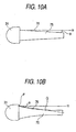
- the support jig preferably has a gradient diameter portion whose outer diameter decreases gradually as the distance from the piercing plug increases. Because the support jig having the gradient diameter portion is provided, resistance acting on the piercing plug can be entirely absorbed to the support jig and can disperse force to thereby prevent the force from acting on the central portion of the support jig. Accordingly, when the diameter of the hole of the glass material is enlarged, the hole can be restrained from becoming eccentric due to deflection of the support jig.
- the gradient diameter portion 76 may have a side surface shaped like a straight line as shown in Fig. 10 (a) or like a curve as shown in Fig. 10 (b) in a section including the axis of the support jig 75.
- the angle ⁇ of the gradient diameter portion 76 with respect to a line m parallel to the axis of the support jig may be preferably selected to be in a range of from 0.1 degrees to 10 degrees, both inclusively.
- the gradient diameter portion 76 is expressed in straight line as shown in Fig. 10(a)
- the angle ⁇ between the straight line and the line m is preferably selected to be in the aforementioned range.
- the angle ⁇ between a straight line connecting a start point P of reduction in diameter and an end point Q of reduction in diameter in the sectional view and the line m is preferably selected to be in the aforementioned range.
- the support jig 75 may be fixed to each of opposite ends of the piercing plug 35.
- a positioning dent configured to allow the piercing plug to be guided to a predetermined position is provided in an end surface of the columnar or cylindrical glass material so that a diameter enlarging member can be made to abut on the positioning dent to start enlargement of the diameter of the hole in the glass material.
- the positioning dent 81a is provided in the exit side end surface of the columnar glass material 3a.
- the positioning dent 81b is provided in the exit side end surface of the cylindrical glass material 3b.
- the glass material 3a (3b) is welded to the supporting pipe 21 at its exit side end surface.
- the piercing plug 31 abuts on the glass material 3a (3b) while being supported by the support rod 32.
- the piercing plug 31 first abuts on the positioning dent 81a (81b), so that sliding in a direction perpendicular to the axis of the glass material 3a (3b) is limited.
- the positioning dent 81a (81b) is preferably configured so that the piercing plug 31 can be guided by the positioning dent 81a (81b) to make the axis of the piercing plug 31 coincident with the axis of the glass material 3a (3b).
- the positioning dent 81a shown in Fig. 11 (a) is shaped like a cone the vertex of which is located at the bottom of the dent.
- the direction Y1 of piercing the glass material 3a is set as a direction of the center axis of the glass material 3a.
- the bottom of the positioning dent 81a abuts on the vertex of the piercing plug 31.
- the angle ⁇ of aperture of the positioning dent is selected to be higher than the vertical angle ⁇ of the piercing plug.
- the axis X1 of the piercing plug can be made coincident with the piercing direction Y1 easily regardless of the surface condition of the exit side end surface of the glass material 3a as shown in Fig. 11(a).
- the positioning dent 81b shown in Fig. 11 (b) can guide the piercing plug 31 in the same manner as described in Fig. 11 (a) except that the positioning dent 81b is shaped like a truncated cone.
- the positioning dent may be shaped like a column but a tapered shape may be preferably used.
- the tapered shape include a truncated cone, a truncated polygonal pyramid, part of a spherical surface or a flattened spherical surface, a curved surface generated by revolution of a curved generatrix, and so on.
- the first embodiment will be described as an embodiment in which an internal or external pressure of a glass tube is controlled to thereby control respective stresses exerted on inner and outer circumferential sides of the glass tube when a piercing plug is pressed into a glass material.
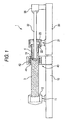
- a glass tube manufacturing apparatus 1 used in this embodiment has a heating furnace 40 for heating a glass rod 3, an entrance side base 10 disposed on an entrance side of the heating furnace 40, and an exit side base 20 disposed on an exit side of the heating furnace 40.
- a dummy pipe 4 (supporting pipe) made of glass is connected to one end of the glass rod 3 which is to be pierced.
- a first feed table 11 capable of being slid left and right in the drawing at a desired speed is provided on the entrance side base 10.
- the first feed table 11 is configured so that a piercing-terminating end side of the glass rod 3 can be grasped by a first chuck 12 and that the glass rod 3 can be rotated about its longitudinal axis.
- a second feed table 21 capable of being slid left and right in the drawing in the same manner as the first feed table 11 is provided on the exit side base 20.
- the moving speed of the second feed table 21 is appropriately controlled in accordance with the moving speed of the first feed table 11.
- the second feed table 21 is configured so that one end of the dummy pipe 4 connected to a piercing-starting end side of the glass rod 3 can be grasped by a second chuck 22 and that the glass rod 3 can be rotated about its longitudinal axis.
- the rotation of the second feed table 21 can be controlled to be synchronized with the rotation of the first feed table 11 or to be made different from the rotation of the first feed table 11.
- a fixing member 35 for fixing a support rod 32 is further provided on the exit side base 20.
- the support rod 32 is fixed to the piercing plug 31 and fixed to the fixing member 35.
- the support rod 32 has such a center axis that the support rod 32 is concentric with the piercing plug 31.
- the support rod 32 is supported so that the center axis of the support rod 32 is made coincident with the center axis of the glass rod 3.
- the piercing plug 31 is made of a material allowed to be used at the softening temperature of the glass rod 3 but substantially incapable of chemically reacting with the glass rod 3.
- the piercing plug 31 is made of black lead (graphite). Black lead is excellent.in stability at a high temperature for softening glass and has high electric conductivity.
- the amount of impurities contained in ordinary black lead is about 400 ppm, it is desirable that high-purity black lead is used for the piercing plug 31 in this embodiment. More desirably, the impurity content is selected to be not higher than 1 ppm. As a result, the amount of impurities moved from the piercing plug 31 into the glass rod 3 can be reduced when the piercing plug 31 is pressed into the glass rod 3.
- the piercing plug 31 is further desirably surface-coated so that at least part of the piercing plug 31 being contact with glass contains any one of silicon carbide (SiC), pyrolytic carbon (PyC) and metal carbide.
- SiC silicon carbide
- PyC pyrolytic carbon
- metal carbide metal carbide.
- niobium carbide (NbC), tantalum carbide (TaC), titanium carbide (TiC) and zircon carbide (ZrC) can be listed as preferred materials for the metal carbide.
- a coating layer of silicon carbide or the like as described above may be formed on a surface of the piercing plug 31 so that oxidization at a high temperature can be prevented while both strength and wear resistance can be improved. Furthermore, the surface coating makes it possible to keep the surface of the piercing plug 31 highly pure and to prevent impurities from diffusing from the inside of the piercing plug 31 into the glass rod 3. The use of a black lead material having a higher surface hardness is also effective in improving both strength and wear resistance.
- the heating furnace 40 in this embodiment is a high frequency induction heat type furnace in which heat is generated by a heating element 41 when an alternating current is passed through a coil 42.
- the heating element 41 is made of black lead, which is cylindrically shaped and with which the neighborhood of an abutment portion between the glass rod 3 and the piercing plug 31 is covered.
- the heating element 41 generates heat to a temperature equal to or higher than the softening point of the glass to thereby heat and soften the glass rod 3.
- the softening point is about 1700°C.
- an air supply hole 45 and an air discharge hole 46 that communicate with a space 47 in which the glass rod 3 is heated are formed in the heating furnace 40.
- the air supply hole 45 is connected to an air supply portion 50 shown in Fig. 2(b).
- the air discharge hole 46 is connected to an air discharge portion 55 shown in Fig. 2(c). It is preferable to perform forced evacuation using a vacuum pump or the like.
- the air supply portion 50 supplies a gas to a supply pipe 53 from a gas supply portion 51 for supplying a desired kind of gas through a mass flow controller (hereinafter referred to as MFC) 52.
- MFC mass flow controller
- the supply pipe 53 is connected to the air supply hole 45 to supply the desired gas toward the space 47 (in the direction of the arrow A1).
- the gas supplied here has no bad influence on the quality of the formed glass tube 6.
- an inert gas such as nitrogen, argon, or the like, may be used.
- the air discharge portion 55 discharges the gas in the space 47 (in the direction of the arrow B1) from an air discharge pipe 56 connected to the air discharge hole 46.
- a pressure gage 57, an MFC 58 and a mechanical damper 60 are provided in streaming order in the air discharge portion 55.
- the pressure gage 57 monitors the pressure of the gas discharged from the space 47 to the air discharge pipe 56.
- the pressure measured by the pressure gage 57 is substantially equal to the internal pressure of the space 47.
- the MFC 58 controls the flow rate of the gas discharged from the space 47 to the mechanical damper 60 on the basis of a required amount of surplus air introduced through an introduction pipe 59 suitably. That is, the flow rate of the gas flowing in the mechanical damper 60 is the sum of the amount of the gas discharged from the space 47 and the amount of the surplus air introduced from the MFC 58.
- the flow rate in the mechanical damper 60 is set so that a desired air discharge amount set in advance can be obtained.
- the mechanical damper 60 has an relief valve 61 provided to prevent the upstream side from being pressurized abnormally.
- the air supply portion 50 and the air discharge portion 55 configured as described above are further configured so that the MFCs 52 and 58 and the pressure gage 57 can be controlled by a single control system.
- the MFCs 52 and 58 can be controlled with reference to the pressure measured by the pressure gage 57 to thereby control both the amount of gas supplied to the space 47 and the amount of gas discharged from the space 47. Accordingly, the pressure of the space 47 can be controlled to have a desired value.
- Sealing portions 43 and 44 by which the space 47 is formed are provided at the entrance and the exit of the heating furnace 40 respectively.
- Each sealing portion 43 (44) is of a non-contact type and is configured so that a'very small gap is provided between the glass rod 3 (pierced glass tube 6) and the sealing portion 43 (44).
- a gas is jetted toward the glass rod 3 or the glass tube 6 so that the gap between the heating furnace 40 and the glass rod 3 or the glass tube 6 is sealed with the gas.
- control is preferably performed so that the barometric pressure of the space 47 becomes a positive pressure compared with the barometric pressure of the external space of the induction heating furnace 40.
- a cap 23 is attached to the end portion of the dummy pipe 4 grasped by the second chuck 22.
- the cap 23 is configured to be fixed to the support rod 32 of the piercing plug hermetically so that the cap 23 cannot rotate relative to the support rod 32 but can rotate relative to the dummy pipe 4 in a hermetically closed state between the cap 23 and the dummy pipe 4 through an O-ring 24.
- An air supply hole 25 and an air discharge hole 26 that communicate with the hole 5 of the glass tube 6 are formed in the cap 23.
- the air supply hole 25 and the air discharge hole 26 are connected to an air supply portion and an air discharge portion equivalent in configuration to the air supply portion 50 shown in Fig. 2(b) and the air discharge portion 55.
- gas a flow rate of which is controlled to have a required value is supplied from the air supply hole 25 into the hole 5 (in the direction of the arrow A2) whereas gas.a flow rate of which is controlled to have a required value is discharged from the hole 5 through the air discharge hole 26 (in the direction of the arrow B2).
- the internal pressure of the hole 5 can be controlled to have a desired value in the same manner as that of the aforementioned space 47.
- the internal pressure of the hole 5 may be either positive pressure or negative pressure (including vacuum).
- the glass rod 3 fed into the heating furnace 40 is heated and softened by heat generated by the heating element 41 and the piercing plug 31 is pressed into the softened region of the glass rod 3 to pierce the glass rod 3 gradually to thereby form the glass tube 6.
- the internal and external pressures of the glass tube 6 can be controlled to control stresses exerted on the inner and outer circumferential sides of the glass tube 6 respectively. Accordingly, the internal and external pressures can be made to act on the glass tube 6 just after piercing so that the shape of the glass tube 6 is sustained. Thus, required inner and outer diameters of the glass tube 6 can be obtained accurately.
- the internal and external pressures of the glass tube 6 may be preferably controlled so that the deviation between the internal and external pressures is kept substantially constant. Particularly when controlling is made so that variation in the barometric pressure deviation between the internal and external pressures is not higher than 13.3 Pa, a glass tube 6 having a uniform shape in the longitudinal direction can be obtained easily.
- a control system for controlling the barometric pressure of the space 47 and a control system for controlling the barometric pressure of the hole 5 may be operated in accordance with respective set values independently or may be linked with each other to perform control to adjust the barometric pressure deviation between the internal and external pressures.
- the second embodiment will be described as an embodiment in which each of stresses exerted on the inner and outer circumferential sides of the glass tube is controlled by inductively heating the piercing plug to a temperature equal to or higher than the softening point of the glass rod when the piercing plug is pressed into the glass rod.
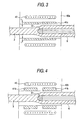
- the glass tube manufacturing apparatus used in this embodiment is substantially the same in configuration as the glass tube manufacturing apparatus 1 shown in Fig. 1. Main part of this embodiment will be described with reference to Fig. 3.
- a heating furnace 40a used in this embodiment is formed so that the thickness t of a heating element 41a is smaller than that of an ordinary heating element.
- the induced current density generated in a member to heat is the highest at the coil side surface of the member and decreases as the location goes from the coil side surface toward the inside of the member (this is referred to as skin effect). That is, in an ordinary induction heating furnace, an induced current is generated only in the heating element of the heating furnace but no induced current is generated in the piercing plug located inside the heating element.
- the use of the heating element 41a thinner than the ordinary heating element makes it possible to generate an induced current also in the piercing plug 31 disposed inside the heating element 41a, so that the piercing plug 31 is positively inductively heated.
- the skin effect of induction heating is determined on the basis of the electric resistance and relative magnetic permeability of the member to heat and the frequency of the alternating current applied to the coil.
- the distance at which the current density is attenuated to 36.7 % when the current density at the coil side surface of the member to heat is regarded as 1 is defined as a depth ⁇ of penetration of the current.
- the frequency of the alternating current applied to the coil is about 40 kHz. In this embodiment, however, a frequency of 10 kHz or lower is used. As a result, the depth of penetration of the induced current increases, so that the induced current can be generated not only in the heating element 41a but also in the piercing plug 31 to heat the piercing plug 31 positively inductively.
- At least one of the heating element 41a and the piercing plug 31 may be formed to have a required electric resistance value so that the induced current can be easily generated in the piercing plug 31.
- the heating element 41a is made of porous black lead, the electric resistance value of the heating element 41a becomes high. As a result, the depth of penetration of the induced current increases so that the induced current can be easily generated in the piercing plug 31.
- one or more method among the method of reducing the thickness t of the heating element 41a, the method of reducing the frequency of the alternating current and the method of setting the electric resistances of the heating element 41a or the piercing plug 31 optionally are selectively employed so that both the heating element 41a and the piercing plug 31 are heated to a temperature equal to or higher than the softening point of glass.
- the frequency of the alternating current is reduced as well as the thickness t of the heating element 41a is reduced, the piercing plug 31 can be effectively inductively heated.
- the temperature of the piercing plug 31 is measured by a non-contact type radiation thermometer or by a thermo couple directly provided on the piercing plug 31.
- the thickness t of the heating element 41a and the electric power of the alternating current applied to the coil 42 are set so that the temperature of the inner circumferential side of the glass tube 6 becomes substantially equal to the temperature of the outer circumferential side of the glass tube 6 when the glass tube 6 is formed.
- the glass tube 6 is not cooled by the piercing plug. Accordingly, heating efficiency is improved so that the electric power for passing the alternating current through the coil 42 can be used effectively.
- the third embodiment will be described as an embodiment for inductively heating the piercing plug to a temperature equal to or higher than the softening point of the glass material in the same manner as in the aforementioned second embodiment.
- a heating furnace 40b used in this embodiment is formed so that the heating element is divided into two parts 41b in the piercing direction of the glass rod 3.
- the piercing plug 31 is disposed at a gap formed between the heating element parts 41b, magnetic flux generated by the coil 42 can be made to directly act on the piercing plug 31. Accordingly, the piercing plug 31 can be exclusively inductively heated to a temperature equal to or higher than the softening point.
- the temperature of the inner circumferential side of the glass tube 6 can be made substantially equal to the temperature of the outer circumferential side of the glass tube 6 to thereby restrain the shape of the glass tube 6 from being distorted, in the same manner as that in the second embodiment.
- the fourth embodiment will be described as an embodiment in which a resistance heating method is used for heating the piercing plug to a temperature equal to or higher than the softening point of the glass material.
- a heating furnace used in this embodiment has the configuration for heating the glass rod 3 to be the same as the heating furnace 40 described in the first embodiment.
- a power supply 65 for passing a current through the piercing plug 31 is connected to the piercing plug 31. Since the piercing plug 31 is made of a material mainly containing carbon as described above, Joule heat can be generated for resistance heating when a current is passed through the piercing plug 31.
- Such a configuration makes it possible to control the heating temperature of each of the heating element 41 of the heating furnace 40 and the piercing plug 31 to thereby make the temperature of the inner circumferential side of the glass tube 6 substantially equal to the temperature of the outer circumferential side of the glass tube 6 when the glass tube 6 is formed. Accordingly, when the glass tube 6 is cooled, stresses exerted on the inner and outer circumferential sides of the glass tube 6 can be controlled to restrain the glass tube 6 from being deformed.
- This embodiment will be described as an embodiment in which the pressure at which the piercing plug is relatively pressed into the glass material is detected and a detection signal of the pressure is fed back so that the quantity of heat generated by the heating element is controlled to keep the pressure constant.
- Fig. 6 shows a glass tube manufacturing apparatus 1 according to this embodiment.
- a high frequency induction furnace is used as the heating furnace 40 that is heating means for softening and processing the glass material.
- the heating furnace 40 is connected to a controller 71 (the arrow G shows a direction of carrying the glass rod 3).
- a load cell 33 as pressure detecting means is mounted between the support rod 32 fixed to a rear end of the piercing plug 31 and the fixing table 35.
- the load cell 33 is connected to the controller 71.
- the first feed table 11 as moving means that grasps the glass rod 3 as a glass material moves on the entrance side base 10 to feed the glass material 3 into the heating element 41.
- a mechanism for moving the first feed table 11 there can be given an example in which a ball screw is provided on the entrance side base 10 whereas a ball nut is formed in the first feed table 11 so that the ball screw thread-engaged with the ball nut is rotated by a motor or the like to move the first feed table 11 on the entrance side base 10.
- support rollers 48 may be provided in an intermediate position to stabilize the attitude of the glass rod 3. The position of each support roller 48 can be adjusted in the up-and-down direction and in the left-and-right direction in the drawing (this also applies to a sixth embodiment).
- the first feed table 11 is moved toward the heating furnace 40 to feed the glass rod 3 at a constant speed.
- the end of the glass rod 3 is pressed outward (toward the outer circumference side) and enlarged by the piercing plug 31, so that the hole 5 is provided in the end of the glass rod 3.
- an inert gas such as N 2 , Ar, or the like is supplied into the heating furnace 40 in the direction of carrying the glass rod 3 (the direction of the arrow G).
- the pressure at which the glass rod 3 is carried in and pressed against the piercing plug 31 is detected by the load cell 33 through the support rod 32 and fed back to the controller 71.
- the controller 71 judges that the glass rod 3 is over-softened, and reduces the quantity of heat generated by the heating element 41 to decrease the temperature of the heating furnace 40.
- the controller 71 judges that the glass rod 3 is,under-softened, and increases the quantity of heat generated by the heating element 41 to increase the temperature of the heating furnace 40.
- Fig. 8 shows a glass tube manufacturing apparatus 1 according to the sixth embodiment.
- the first feed table 11 is self-propelled by a motor 62.
- Numerical values such as a current, a voltage, etc., supplied to the motor 62 are detected by the controller 71.
- the controller 71 judges that the glass rod 3 is over-softened, and decreases the temperature of the heating furnace 40 (incidentally, the arrow G indicates the direction of carrying the glass rod 3).
- the controller 71 judges that the glass rod 3 is under-softened, and increases the temperature of the heating furnace 40. In this manner, the softened state of the glass rod 3 can be detected on the basis of the detected current or voltage value of the driving motor 62 of the first feed table 11. Accordingly, feedback control for increasing or decreasing the temperature of the heating furnace 40 can be carried out by the controller 71 according to the detected current or voltage value so that the softened state of the glass rod 3 fed into the heating furnace 40 can be always kept constant.
- a glass tube manufacturing apparatus 1 has a mass flow controller 73.
- a muffle tube 72 is disposed in a heating furnace 31 of the manufacturing apparatus 1.
- the glass tube is manufactured in the muffle tube 72.
- An inert gas e.g., helium etc. high in thermal conductivity
- the softened state of the glass rod 3 disposed in the muffle tube 72 is judged from the load cell 33 connected to the aforementioned support rod 32, the current or voltage value of the motor 62 for driving the first feed table 11, or the like.
- the flow rate of the inert gas introduced into the muffle tube 72 is controlled to make the temperature control possible.
- the mass flow controller 73 is controlled to increase the flow rate of the inert gas to make it possible to decrease the temperature of the atmosphere in the muffle tube 72 slightly.
- the flow rate of the inert gas is decreased by the mass flow controller 73 to make it possible to increase the temperature of the atmosphere slightly.
- the glass rod can be always pierced at constant viscosity, stress exerted on the inner circumference of the glass tube can be controlled to prevent variations in residual stress and dimensions. Accordingly, it is possible to avoid the problem that cracks are apt to occur at the time of reheating because residual stress after cooling is distributed or that lengthwise characteristic varies after fiber formation because dimensional accuracy after processing deteriorates.
- the quantity of the inert gas supplied between the heating furnace and the glass material can be controlled simultaneously to thereby attain improvement in the response and precision of control.
- the method and the apparatus for manufacturing a glass tube according to the invention is not limited to the aforementioned embodiments and changes, modifications, etc., may be made suitably.
- detection means for detecting the current or voltage supplied to the motor may be provided so that the pressure can be judged from consumed electric power.
- the first through seventh embodiments may be implemented in combination.
- the first and second embodiments are combined so that the internal and external pressures of the glass tube and the temperature of the glass tube are controlled simultaneously, the shape of the glass tube can be more effectively prevented from being distorted.
- the method for manufacturing a glass tube according to the invention may be also applied to the case where the inner diameter of the hole of a glass pipe as a cylindrical glass material is enlarged.
- a high-quality glass tube can be obtained because the glass tube can be prevented from being deformed just after piercing. It is also possible to solve the problem that cracks are apt to occur at the time of reheating because residual stress after cooling is distributed.
- the glass tube manufactured according to the invention is preferred as a material of an optical fiber.
- the glass tube is filled with glass layers formed on the inner surface of the glass tube so that an optical fiber preform having a central portion high in refractive index is obtained as a solid product.
- a core rod is inserted into the glass tube so that an optical fiber preform is obtained as a solid product. The optical fiber preform obtained thus is drawn to produce an optical fiber.
Landscapes
- Chemical & Material Sciences (AREA)
- Engineering & Computer Science (AREA)
- Materials Engineering (AREA)
- Organic Chemistry (AREA)
- Manufacturing & Machinery (AREA)
- Chemical Kinetics & Catalysis (AREA)
- Life Sciences & Earth Sciences (AREA)
- General Life Sciences & Earth Sciences (AREA)
- Geochemistry & Mineralogy (AREA)
- Re-Forming, After-Treatment, Cutting And Transporting Of Glass Products (AREA)
Applications Claiming Priority (13)
| Application Number | Priority Date | Filing Date | Title |
|---|---|---|---|
| JP2002022444 | 2002-01-30 | ||
| JP2002022451A JP4062410B2 (ja) | 2002-01-30 | 2002-01-30 | 光ファイバ用ガラスパイプの製造方法および製造装置 |
| JP2002022451 | 2002-01-30 | ||
| JP2002022566 | 2002-01-30 | ||
| JP2002022444A JP4062409B2 (ja) | 2002-01-30 | 2002-01-30 | 光ファイバ用ガラスパイプの製造方法 |
| JP2002022566A JP2003221251A (ja) | 2002-01-30 | 2002-01-30 | 光ファイバ用ガラスパイプの製造装置、光ファイバ用ガラスパイプの製造方法、及び、光ファイバ用母材の製造方法 |
| JP2002028779A JP4120769B2 (ja) | 2002-02-05 | 2002-02-05 | 石英パイプの製造方法および製造装置 |
| JP2002028779 | 2002-02-05 | ||
| JP2002201861 | 2002-07-10 | ||
| JP2002201861A JP4221553B2 (ja) | 2002-07-10 | 2002-07-10 | ガラス管の製造方法 |
| JP2002233926 | 2002-08-09 | ||
| JP2002233926A JP4244591B2 (ja) | 2002-08-09 | 2002-08-09 | ガラス管の製造方法 |
| PCT/JP2003/000841 WO2003064338A1 (fr) | 2002-01-30 | 2003-01-29 | Procede et dispositif de fabrication de tube de verre |
Publications (2)
| Publication Number | Publication Date |
|---|---|
| EP1471040A1 true EP1471040A1 (fr) | 2004-10-27 |
| EP1471040A4 EP1471040A4 (fr) | 2005-08-17 |
Family
ID=27671277
Family Applications (1)
| Application Number | Title | Priority Date | Filing Date |
|---|---|---|---|
| EP03703074A Withdrawn EP1471040A4 (fr) | 2002-01-30 | 2003-01-29 | Procede et dispositif de fabrication de tube de verre |
Country Status (5)
| Country | Link |
|---|---|
| US (1) | US6997016B2 (fr) |
| EP (1) | EP1471040A4 (fr) |
| KR (1) | KR20040078640A (fr) |
| CN (1) | CN1564789A (fr) |
| WO (1) | WO2003064338A1 (fr) |
Cited By (4)
| Publication number | Priority date | Publication date | Assignee | Title |
|---|---|---|---|---|
| WO2006039705A3 (fr) * | 2004-09-30 | 2006-06-01 | Becton Dickinson Co | Procede permettant de reduire ou d'eliminer des residus dans un contenant en verre et contenant en verre ainsi obtenu |
| WO2012085619A1 (fr) * | 2010-12-20 | 2012-06-28 | Becton Dickinson France | Outil pour la formation de récipients en verre à usage médical exempts de contamination par un élément étranger |
| WO2013131720A1 (fr) * | 2012-03-08 | 2013-09-12 | Schott Ag | Outil de moulage, procédé et dispositif de façonnage de verre assisté par laser |
| DE102015117422A1 (de) | 2015-10-13 | 2017-04-13 | Schott Ag | Wolfram-haltiger Formdorn zur Glasformung |
Families Citing this family (6)
| Publication number | Priority date | Publication date | Assignee | Title |
|---|---|---|---|---|
| WO2003059828A1 (fr) * | 2002-01-17 | 2003-07-24 | Sumitomo Electric Industries, Ltd. | Procede et dispositif de fabrication d'un tube de verre |
| DE102015117215B4 (de) * | 2015-10-08 | 2019-03-14 | Gerresheimer Bünde Gmbh | Vorrichtung und Verfahren zur Herstellung eines medizinischen Glasbehälters |
| DE102018100443A1 (de) * | 2018-01-10 | 2019-07-11 | Schott Ag | Verfahren und Vorrichtung zur Herstellung von Glasvorprodukten und von Glasprodukten |
| EP3766840B1 (fr) * | 2019-07-17 | 2024-11-20 | Heraeus Quarzglas GmbH & Co. KG | Procédé de fabrication d'une fibre à coeur creux et de fabrication d'une préforme de fibre à coeur creux |
| CN110540358B (zh) * | 2019-08-19 | 2022-05-03 | 湖州维德光电科技有限公司 | 一种一体成形球棒的设备 |
| CN114988674A (zh) * | 2022-06-17 | 2022-09-02 | 东莞市聚泰玻璃有限公司 | 一种玻璃加工设备 |
Family Cites Families (14)
| Publication number | Priority date | Publication date | Assignee | Title |
|---|---|---|---|---|
| US3293018A (en) * | 1963-09-18 | 1966-12-20 | Chevron Res | Flange forming fixture and method |
| US3660062A (en) * | 1968-02-29 | 1972-05-02 | Siemens Ag | Method for crucible-free floating zone melting a crystalline rod, especially of semi-crystalline material |
| US4350513A (en) * | 1981-11-23 | 1982-09-21 | Western Electric Company, Inc. | Method and apparatus for extruding glass tubes |
| JPS62162632A (ja) * | 1986-01-14 | 1987-07-18 | Sumitomo Electric Ind Ltd | ガラスパイプの加工方法 |
| JPS6340735A (ja) * | 1986-07-31 | 1988-02-22 | Masahiro Shigesane | ガラス容器の内面処理方法 |
| JP2798465B2 (ja) * | 1990-02-27 | 1998-09-17 | 日本石英硝子株式会社 | 石英ガラス製シリンダーの製造法及び装置 |
| JP3039789B2 (ja) * | 1990-05-22 | 2000-05-08 | 旭硝子株式会社 | 合成石英ガラス管の製造方法 |
| EP0598349B1 (fr) * | 1992-11-19 | 1998-07-29 | Shin-Etsu Quartz Products Co., Ltd. | Procédé pour la fabrication d'un tube en verre de quartz à grande dimension, d'une préforme et d'une fibre optique |
| US5837344A (en) * | 1996-08-22 | 1998-11-17 | Gunther Technologies, Inc. | Spiral coil binding system |
| JP4040127B2 (ja) * | 1996-09-27 | 2008-01-30 | 信越石英株式会社 | 石英ガラス管の製造方法とその装置 |
| CN1125788C (zh) * | 1998-02-03 | 2003-10-29 | 住友电气工业株式会社 | 光纤母材的制造方法 |
| JP3800930B2 (ja) * | 2000-06-26 | 2006-07-26 | 住友金属工業株式会社 | 石英ガラスシリンダおよび石英ガラス管とその製造方法 |
| DE10044715C1 (de) * | 2000-09-08 | 2001-12-06 | Heraeus Quarzglas | Verfahren zur Herstellung eines Quarzglasrohres und Bohrkörper zur Durchführung des Verfahrens |
| US20030046956A1 (en) * | 2001-08-30 | 2003-03-13 | Anderson James G. | Method and apparatus for crucible forming |
-
2003
- 2003-01-29 CN CNA038012340A patent/CN1564789A/zh active Pending
- 2003-01-29 KR KR10-2004-7004158A patent/KR20040078640A/ko not_active Withdrawn
- 2003-01-29 WO PCT/JP2003/000841 patent/WO2003064338A1/fr not_active Ceased
- 2003-01-29 EP EP03703074A patent/EP1471040A4/fr not_active Withdrawn
-
2004
- 2004-03-10 US US10/796,052 patent/US6997016B2/en not_active Expired - Fee Related
Cited By (9)
| Publication number | Priority date | Publication date | Assignee | Title |
|---|---|---|---|---|
| WO2006039705A3 (fr) * | 2004-09-30 | 2006-06-01 | Becton Dickinson Co | Procede permettant de reduire ou d'eliminer des residus dans un contenant en verre et contenant en verre ainsi obtenu |
| US9994477B2 (en) | 2004-09-30 | 2018-06-12 | Becton, Dickinson And Company | Method for reducing or eliminating residue in a glass container and a glass container made in accordance therewith |
| US11040905B2 (en) | 2004-09-30 | 2021-06-22 | Becton, Dickinson And Company | Method for reducing or eliminating residue in a glass container and a glass container made in accordance therewith |
| WO2012085619A1 (fr) * | 2010-12-20 | 2012-06-28 | Becton Dickinson France | Outil pour la formation de récipients en verre à usage médical exempts de contamination par un élément étranger |
| WO2013131720A1 (fr) * | 2012-03-08 | 2013-09-12 | Schott Ag | Outil de moulage, procédé et dispositif de façonnage de verre assisté par laser |
| CN104159857A (zh) * | 2012-03-08 | 2014-11-19 | 肖特公开股份有限公司 | 用于激光辅助的玻璃成形的成形工具、方法和设备 |
| DE102015117422A1 (de) | 2015-10-13 | 2017-04-13 | Schott Ag | Wolfram-haltiger Formdorn zur Glasformung |
| EP3156377A1 (fr) | 2015-10-13 | 2017-04-19 | Schott AG | Mandrin de formage contenant du tungstène pour le formage du verre |
| US10675407B2 (en) | 2015-10-13 | 2020-06-09 | Schott Ag | Tungsten containing forming mandrel for glass forming |
Also Published As
| Publication number | Publication date |
|---|---|
| US6997016B2 (en) | 2006-02-14 |
| EP1471040A4 (fr) | 2005-08-17 |
| CN1564789A (zh) | 2005-01-12 |
| WO2003064338A1 (fr) | 2003-08-07 |
| US20040231361A1 (en) | 2004-11-25 |
| KR20040078640A (ko) | 2004-09-10 |
Similar Documents
| Publication | Publication Date | Title |
|---|---|---|
| US6997016B2 (en) | Method and apparatus for manufacturing glass tube | |
| US6516636B1 (en) | Method for producing a tube made of quartz glass using low internal pressure and control of diameters | |
| JP4574420B2 (ja) | 既定の内部形状を有する校正された円形又は異形のガラス管を連続的に製造する方法 | |
| US9834467B2 (en) | Method and apparatus for making a profiled tubing and a sleeve | |
| US20100064733A1 (en) | Glass tube processing method, apparatus and glass tube | |
| US9328012B2 (en) | Glass base material elongating method | |
| JP7784937B2 (ja) | シリカガラスから成る管及びこの管の製造方法 | |
| KR20040077449A (ko) | 유리관의 제조 방법 및 제조 장치 | |
| US20030019246A2 (en) | Method and device for producing a quartz glass body | |
| EP0630866A1 (fr) | Procédé et appareil pour la fabrication d'une préforme pour fibre optique | |
| JP6722946B2 (ja) | スピニング加工装置 | |
| CN101157514A (zh) | 制造拉制玻璃部件、隔板以及图像显示装置的方法 | |
| JP4226364B2 (ja) | 光ファイバ母材の製造方法 | |
| JP4443433B2 (ja) | 光ファイバ母材延伸方法 | |
| JP4244591B2 (ja) | ガラス管の製造方法 | |
| JP4450533B2 (ja) | 光ファイバ母材の製造方法 | |
| KR100306363B1 (ko) | 광섬유 모재의 테이퍼 형성 방지 장치 | |
| JP4239595B2 (ja) | 光ファイバ母材の製造方法 | |
| JP2007008763A (ja) | 石英ガラス管の製造方法および製造装置 | |
| EP3243803B1 (fr) | Préforme de verre pour fibre optique et procédé de fabrication de fibre optique | |
| WO2004035494A1 (fr) | Procede de production de materiau-mere de fibre optique, materiau-mere de fibre optique, fibre optique, dispositif de production de materiau-mere de fibre optique | |
| JP2007320803A (ja) | ガラスパイプの製造方法 | |
| JP2004277245A (ja) | 光ファイバ母材の製造方法 | |
| JP2005336030A (ja) | 光ファイバ用ガラス母材の製造方法 | |
| JP2004277246A (ja) | 光ファイバ母材の製造装置及び製造方法 |
Legal Events
| Date | Code | Title | Description |
|---|---|---|---|
| PUAI | Public reference made under article 153(3) epc to a published international application that has entered the european phase |
Free format text: ORIGINAL CODE: 0009012 |
|
| 17P | Request for examination filed |
Effective date: 20040311 |
|
| AK | Designated contracting states |
Kind code of ref document: A1 Designated state(s): AT BE BG CH CY CZ DE DK EE ES FI FR GB GR HU IE IT LI LU MC NL PT SE SI SK TR |
|
| A4 | Supplementary search report drawn up and despatched |
Effective date: 20050630 |
|
| RIC1 | Information provided on ipc code assigned before grant |
Ipc: 7C 03B 23/045 A Ipc: 7C 03B 23/047 B Ipc: 7C 03B 37/012 B Ipc: 7C 03B 23/049 B |
|
| STAA | Information on the status of an ep patent application or granted ep patent |
Free format text: STATUS: THE APPLICATION HAS BEEN WITHDRAWN |
|
| 18W | Application withdrawn |
Effective date: 20140203 |