EP1471184A2 - Dispositif d'elimination de boue - Google Patents
Dispositif d'elimination de boue Download PDFInfo
- Publication number
- EP1471184A2 EP1471184A2 EP04076191A EP04076191A EP1471184A2 EP 1471184 A2 EP1471184 A2 EP 1471184A2 EP 04076191 A EP04076191 A EP 04076191A EP 04076191 A EP04076191 A EP 04076191A EP 1471184 A2 EP1471184 A2 EP 1471184A2
- Authority
- EP
- European Patent Office
- Prior art keywords
- mud
- solution
- tank
- phosphating
- line
- Prior art date
- Legal status (The legal status is an assumption and is not a legal conclusion. Google has not performed a legal analysis and makes no representation as to the accuracy of the status listed.)
- Withdrawn
Links
Images


Classifications
-
- C—CHEMISTRY; METALLURGY
- C23—COATING METALLIC MATERIAL; COATING MATERIAL WITH METALLIC MATERIAL; CHEMICAL SURFACE TREATMENT; DIFFUSION TREATMENT OF METALLIC MATERIAL; COATING BY VACUUM EVAPORATION, BY SPUTTERING, BY ION IMPLANTATION OR BY CHEMICAL VAPOUR DEPOSITION, IN GENERAL; INHIBITING CORROSION OF METALLIC MATERIAL OR INCRUSTATION IN GENERAL
- C23C—COATING METALLIC MATERIAL; COATING MATERIAL WITH METALLIC MATERIAL; SURFACE TREATMENT OF METALLIC MATERIAL BY DIFFUSION INTO THE SURFACE, BY CHEMICAL CONVERSION OR SUBSTITUTION; COATING BY VACUUM EVAPORATION, BY SPUTTERING, BY ION IMPLANTATION OR BY CHEMICAL VAPOUR DEPOSITION, IN GENERAL
- C23C22/00—Chemical surface treatment of metallic material by reaction of the surface with a reactive liquid, leaving reaction products of surface material in the coating, e.g. conversion coatings, passivation of metals
-
- B—PERFORMING OPERATIONS; TRANSPORTING
- B01—PHYSICAL OR CHEMICAL PROCESSES OR APPARATUS IN GENERAL
- B01D—SEPARATION
- B01D21/00—Separation of suspended solid particles from liquids by sedimentation
- B01D21/02—Settling tanks with single outlets for the separated liquid
-
- B—PERFORMING OPERATIONS; TRANSPORTING
- B01—PHYSICAL OR CHEMICAL PROCESSES OR APPARATUS IN GENERAL
- B01D—SEPARATION
- B01D21/00—Separation of suspended solid particles from liquids by sedimentation
- B01D21/24—Feed or discharge mechanisms for settling tanks
- B01D21/2405—Feed mechanisms for settling tanks
-
- B—PERFORMING OPERATIONS; TRANSPORTING
- B01—PHYSICAL OR CHEMICAL PROCESSES OR APPARATUS IN GENERAL
- B01D—SEPARATION
- B01D21/00—Separation of suspended solid particles from liquids by sedimentation
- B01D21/24—Feed or discharge mechanisms for settling tanks
- B01D21/2427—The feed or discharge opening located at a distant position from the side walls
-
- C—CHEMISTRY; METALLURGY
- C23—COATING METALLIC MATERIAL; COATING MATERIAL WITH METALLIC MATERIAL; CHEMICAL SURFACE TREATMENT; DIFFUSION TREATMENT OF METALLIC MATERIAL; COATING BY VACUUM EVAPORATION, BY SPUTTERING, BY ION IMPLANTATION OR BY CHEMICAL VAPOUR DEPOSITION, IN GENERAL; INHIBITING CORROSION OF METALLIC MATERIAL OR INCRUSTATION IN GENERAL
- C23C—COATING METALLIC MATERIAL; COATING MATERIAL WITH METALLIC MATERIAL; SURFACE TREATMENT OF METALLIC MATERIAL BY DIFFUSION INTO THE SURFACE, BY CHEMICAL CONVERSION OR SUBSTITUTION; COATING BY VACUUM EVAPORATION, BY SPUTTERING, BY ION IMPLANTATION OR BY CHEMICAL VAPOUR DEPOSITION, IN GENERAL
- C23C22/00—Chemical surface treatment of metallic material by reaction of the surface with a reactive liquid, leaving reaction products of surface material in the coating, e.g. conversion coatings, passivation of metals
- C23C22/86—Regeneration of coating baths
Definitions
- the present invention refers to a mud-removal apparatus in particular intended for plants for spray-phosphating through zinc phosphates.
- Such a layer creates a valid barrier against corrosion and substantially increases the resistance of the varnished layer.
- the spraying of the products usually takes place inside a tunnel, through a piping circuit with suitable nozzles, supplied by a centrifugal pump that, in turn, draws from a tank below the tunnel.
- a closed circuit is thus realised that allows the most advantageous use of products.
- the collection tank requires rather high volumes and consequently, in general, has a substantially long bottom.
- the chemical formation process of the phosphate layer has the intrinsic and unavoidable drawback of the formation of mud created by the reaction sub-product, mainly consisting of insoluble mixtures of ferric phosphates.
- This mud that is generated as a result of 4 ⁇ 6 grams for every m 2 of laminate chemically treated, is an agent that interferes with the correct execution of the treatment and also, in the case in which they come into contact with the spraying circuit, relatively quickly cause the clogging of the piping and of the nozzles with the consequent operating difficulty of the plant.
- the problem is complex since, given the extension of the tank, the speed of movement of the liquid inside of it becomes very low allowing the decanting of the mud on the bottom of the tank and making its removal difficult.
- figures 1 to 4 illustrate plants and their variants according to the prior art, in which it is foreseen to suck the solution from the tank and to continuously filter the phosphating solution.
- the aforementioned plants comprise a phosphating tank 1, comprising a bottom 1a and supplied through a phosphating solution line 7.
- the solution is withdrawn from such a tank through a pump P1 of a spraying system 2 that carries out the spraying of the products.
- an extraction line 3 is foreseen equipped with an extraction pump P2 that withdraws the solution with the mud from the tank and sends it to an external purification or filtration system F1.
- the concentrated mud is then separated and taken to the dump, whereas the clarified phosphating solution can be recovered and return into the tank through a recovery line 9.
- the removal line 3 has a diversion 8 to supply a decanter reservoir 4 suitable for receiving the solution during the cleaning operations of the tank.
- This system has a drawback that is difficult to overcome that concerns the mud deposits on the bottom of the phosphating tank.
- the system is also heavily influenced by the capacity of the pump interlocked to the filter and by the type of filter itself.
- Plants realised in accordance with that which has been described here distinguish themselves for the type of filter used and for the presence or not of an agitation system 6 obtained through leakage from the line 3 after the pump P2 so as to readmit a part of the solution to be clarified to keep that which is still in the tank agitated, thus slowing down the sedimentation of the mud.
- Such a system is used for plants with very limited production; it has substantial drawbacks both due to the easy clogging of the sleeves and due to their difficult maintenance.
- the collected mud is not very substantial in dry residue and is no greater than 2 ⁇ 3%.
- the second system illustrated in figure 2 foresees a filter F1 with a continuous band, and the presence of agitation; such a system is an improvement of the first system.
- the band slides automatically and is collected, together with the mud, in an easily removable container with advantages of management and evacuation of mud.
- the collected mud is not very substantial in dry residue.
- the third system foresees a presser filter, illustrated in particular in figure 3, represents a subsequent improvement.
- Mud is produced with very high dry residue and, with a suitable piping system and a suitable capacity P2, the residue in the tank can be limited, but not eliminated.
- a fourth system foresees a continuous filter with a pressurised band.
- the mud produced is substantial in amount and, with suitable capacity of P2, the residue in the tank is also limited, whilst on the other hand it is the most expensive system.
- the phosphating tank due to considerations of suitability and cost, is usually constructed with its bottom at ground level and, necessarily, with not much of a tilt.
- suction of P2 is arranged in succession in the series of pyramids.
- the cycle foresees that the phosphating bath is emptied every evening so as to accurately clean both the tank and the accessories contained in it.
- the mud produced is then collected and sent through a pump P3 to a filtration system F1 (usually pressurised) to be further pressed obtaining panels with a very high dry percentage, whereas the liquid phase is recovered.
- a filtration system F1 usually pressurised
- the main purpose of the present invention is therefore that of realising a mud-removal apparatus capable of operating continuously through removal of mud during the normal workshifts so as to allow the pollution inside the tank to be kept to optimal, i.e. very low, levels.
- Another purpose of the invention is that of realising a tank that is small in size so that the apparatus is cost-effective to construct and compact, as well as simple to maintain and clean.
- the tank is used to carry out the continuous sedimentation of the mud and to send the phosphating tank a clarified solution suitable for lowering the concentration of mud in the phosphating tank and keep it in constant agitation.
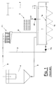
- the tank 11 is equipped with a bottom 11a tilted towards a discharge zone of the solution from the tank from which for this purpose a duct 30 extends through which the phosphating solution returning from spraying is removed from the tank and sent to a continuous decanting system 21 and then to a filtering system F1 with which the apparatus is equipped.
- Such a filtering system F1 that can be chosen, based upon the presumed volumes of mud, to be continuous or discontinuous, is realised in the exemplified form of the invention as a continuous filter with a pressurised band.
- the filter F1 is connected both to the decanting reservoir for normal work and to the phosphating tank 11 for maintenance work, so as to allow the continuous filtration of the mud and the clarification of part of the solution removed from the tank.
- the apparatus according to the invention in order to allow a sufficiently high flow rate of the solution to be clarified so as to reduce the sedimentation of mud in the phosphating tank 11, comprises a sedimentation reservoir 21 connected to the tank and intended to continuously receive the solution to be clarified to carry out the sedimentation of the mud and to send the phosphating tank 11 a clarified solution so as to lower the concentration of mud in the solution in the phosphating tank 11 and keep it in constant agitation.
- the sedimentation reservoir 21, in the lower part, has a frusto-conical decanting section that is used as a continuous decanter of the mud.
- the decanted mud is removed from the end point of the cone.
- the mud-removal apparatus foresees that the sedimentation reservoir 21 is equipped with a suitable insulating layer 22 to keep the temperature of the solution supplied into it constant.
- the phosphating tank 11 is connected to the sedimentation reservoir 21 through a first supply line 13 of the solution to be clarified equipped with passage indicators 25.
- Such a first supply line 13 of the solution to be clarified is also provided with a recirculation line 16 that has a plurality of nozzles at the end arranged along the tank to increase the agitation of the solution inside it and to carry out an effective cleaning thereof during maintenance.
- a transfer pump P2 is also foreseen, preferably used for transferring the solution to be clarified and also to avoid the sedimentation of mud in the phosphating tank 11.
- the phosphating tank 11 is also connected to the sedimentation reservoir 21 through a second recirculation line 23 that can be intercepted through a commanded valve 24 so as to direct the clarified solution back to the phosphating tank.
- the sedimentation reservoir 21 is also provided with a removal line 26 of the mud to which a removal pump P3 is connected to send the solution with a high concentration of mud to the filter F1.
- the mud-removal line 26 upstream of said removal pump P3 foresees the insertion of the emptying duct 30 coming from the bottom of the phosphating tank.
- the filter F1 has, in output, a clarified solution line 28 directed to the phosphating tank 11 that branches into a recirculation line 28' of the clarified solution suitable for supplying said sedimentation reservoir 21.
Landscapes
- Chemical & Material Sciences (AREA)
- Chemical Kinetics & Catalysis (AREA)
- General Chemical & Material Sciences (AREA)
- Engineering & Computer Science (AREA)
- Materials Engineering (AREA)
- Mechanical Engineering (AREA)
- Metallurgy (AREA)
- Organic Chemistry (AREA)
- Chemical Treatment Of Metals (AREA)
Applications Claiming Priority (2)
| Application Number | Priority Date | Filing Date | Title |
|---|---|---|---|
| ITMI20030835 | 2003-04-22 | ||
| IT000835A ITMI20030835A1 (it) | 2003-04-22 | 2003-04-22 | Apparecchiatura di defangazione. |
Publications (2)
| Publication Number | Publication Date |
|---|---|
| EP1471184A2 true EP1471184A2 (fr) | 2004-10-27 |
| EP1471184A3 EP1471184A3 (fr) | 2008-11-19 |
Family
ID=32948207
Family Applications (1)
| Application Number | Title | Priority Date | Filing Date |
|---|---|---|---|
| EP04076191A Withdrawn EP1471184A3 (fr) | 2003-04-22 | 2004-04-20 | Dispositif d'elimination de boue |
Country Status (2)
| Country | Link |
|---|---|
| EP (1) | EP1471184A3 (fr) |
| IT (1) | ITMI20030835A1 (fr) |
Cited By (3)
| Publication number | Priority date | Publication date | Assignee | Title |
|---|---|---|---|---|
| CN108193203A (zh) * | 2018-01-25 | 2018-06-22 | 暨南大学 | 一种涂装磷化除渣系统 |
| CN115814506A (zh) * | 2022-11-23 | 2023-03-21 | 东风柳州汽车有限公司 | 一种磷化槽除渣系统及方法 |
| CN116143089A (zh) * | 2023-01-10 | 2023-05-23 | 昆明理工大学 | 磷化铟回收装置 |
Family Cites Families (5)
| Publication number | Priority date | Publication date | Assignee | Title |
|---|---|---|---|---|
| BE551575A (fr) * | 1955-10-07 | |||
| GB1361489A (en) * | 1971-05-12 | 1974-07-24 | Carrier Drysys Ltd | Removing sludge formed in solutions used in metal pre-treatment processes |
| DE4420760C1 (de) * | 1993-07-01 | 1995-05-11 | Gerd Wurster | Verfahren und Anlage zur Wiederaufarbeitung oder Aufkonzentration verbrauchter tensidhaltiger Eisenphosphatierbäder |
| DE4412363C2 (de) * | 1994-04-11 | 1998-10-29 | Bayerische Motoren Werke Ag | Verfahren zum Behandeln von Phosphatschlamm |
| US5853597A (en) * | 1995-09-28 | 1998-12-29 | Kawasaki Steel Corporation | Method of and apparatus for discharging sedimentary solid particles |
-
2003
- 2003-04-22 IT IT000835A patent/ITMI20030835A1/it unknown
-
2004
- 2004-04-20 EP EP04076191A patent/EP1471184A3/fr not_active Withdrawn
Cited By (3)
| Publication number | Priority date | Publication date | Assignee | Title |
|---|---|---|---|---|
| CN108193203A (zh) * | 2018-01-25 | 2018-06-22 | 暨南大学 | 一种涂装磷化除渣系统 |
| CN115814506A (zh) * | 2022-11-23 | 2023-03-21 | 东风柳州汽车有限公司 | 一种磷化槽除渣系统及方法 |
| CN116143089A (zh) * | 2023-01-10 | 2023-05-23 | 昆明理工大学 | 磷化铟回收装置 |
Also Published As
| Publication number | Publication date |
|---|---|
| ITMI20030835A1 (it) | 2004-10-23 |
| EP1471184A3 (fr) | 2008-11-19 |
Similar Documents
| Publication | Publication Date | Title |
|---|---|---|
| NO763274L (fr) | ||
| CN105936409B (zh) | 一种粉煤输送皮带清洗装置 | |
| CN213375258U (zh) | 一种蓄水池 | |
| JP6385306B2 (ja) | ベルト型ろ過濃縮機のベルト洗浄装置 | |
| CN203853320U (zh) | 一种自动净化清洗装置 | |
| CN101564616B (zh) | 高炉冲渣水净化系统及其方法 | |
| JP5030912B2 (ja) | 脱水機および脱水機のベルト洗浄方法 | |
| CN217351548U (zh) | 酸洗池酸液添加除杂系统及钢管酸洗生产线 | |
| CN105828901B (zh) | 沉淀池用沉淀物排出装置 | |
| US20030143929A1 (en) | Method and system for cleaning workpieces by wet blasting | |
| CN207575946U (zh) | 便于污水回收的陶瓷过滤机 | |
| CN208527497U (zh) | 一种led灯具压铸件的清洗系统 | |
| CN204798907U (zh) | 一种串联式淤泥沉积池 | |
| JP2018114454A (ja) | し渣搬送装置 | |
| CN217149117U (zh) | 一种餐厨垃圾油脂回收装置 | |
| CN212491932U (zh) | 具上置沉泥槽的循环水箱 | |
| CN210905100U (zh) | 一种预制构件环形生产线的清洗系统 | |
| CN208136994U (zh) | 一种治理黄河泥沙清淤装置 | |
| CN203768465U (zh) | 一种净浊分区的脱脂液循环罐 | |
| CN110835102B (zh) | 一种黄磷生产过程中粗磷净化连续操作系统及方法 | |
| RO123197B1 (ro) | Instalaţie şi procedeu pentru prelucrarea reziduurilor petroliere | |
| CN207375773U (zh) | 一种便于底部积矿冲洗的陶瓷过滤机 | |
| CN211035573U (zh) | 一种固定式超稠油除油罐 | |
| US3796372A (en) | Apparatus for removing sludge | |
| CN223752868U (zh) | 一种镀锌液的回收过滤装置 |
Legal Events
| Date | Code | Title | Description |
|---|---|---|---|
| PUAI | Public reference made under article 153(3) epc to a published international application that has entered the european phase |
Free format text: ORIGINAL CODE: 0009012 |
|
| AK | Designated contracting states |
Kind code of ref document: A2 Designated state(s): AT BE BG CH CY CZ DE DK EE ES FI FR GB GR HU IE IT LI LU MC NL PL PT RO SE SI SK TR |
|
| AX | Request for extension of the european patent |
Extension state: AL HR LT LV MK |
|
| PUAL | Search report despatched |
Free format text: ORIGINAL CODE: 0009013 |
|
| AK | Designated contracting states |
Kind code of ref document: A3 Designated state(s): AT BE BG CH CY CZ DE DK EE ES FI FR GB GR HU IE IT LI LU MC NL PL PT RO SE SI SK TR |
|
| AX | Request for extension of the european patent |
Extension state: AL HR LT LV MK |
|
| RIC1 | Information provided on ipc code assigned before grant |
Ipc: C23C 22/86 20060101ALI20081016BHEP Ipc: B01D 21/00 20060101ALI20081016BHEP Ipc: E02B 3/00 20060101AFI20040817BHEP |
|
| AKX | Designation fees paid | ||
| REG | Reference to a national code |
Ref country code: DE Ref legal event code: 8566 |
|
| STAA | Information on the status of an ep patent application or granted ep patent |
Free format text: STATUS: THE APPLICATION IS DEEMED TO BE WITHDRAWN |
|
| 18D | Application deemed to be withdrawn |
Effective date: 20090520 |