EP1471273A2 - Linearführungseinheit - Google Patents
Linearführungseinheit Download PDFInfo
- Publication number
- EP1471273A2 EP1471273A2 EP20040009733 EP04009733A EP1471273A2 EP 1471273 A2 EP1471273 A2 EP 1471273A2 EP 20040009733 EP20040009733 EP 20040009733 EP 04009733 A EP04009733 A EP 04009733A EP 1471273 A2 EP1471273 A2 EP 1471273A2
- Authority
- EP
- European Patent Office
- Prior art keywords
- track
- faces
- slider
- guide rail
- face
- Prior art date
- Legal status (The legal status is an assumption and is not a legal conclusion. Google has not performed a legal analysis and makes no representation as to the accuracy of the status listed.)
- Withdrawn
Links
- 230000036316 preload Effects 0.000 claims abstract description 34
- 230000005489 elastic deformation Effects 0.000 abstract description 12
- 238000004458 analytical method Methods 0.000 description 13
- 238000000034 method Methods 0.000 description 13
- 238000005096 rolling process Methods 0.000 description 12
- 238000009826 distribution Methods 0.000 description 11
- 238000007493 shaping process Methods 0.000 description 10
- 230000002093 peripheral effect Effects 0.000 description 7
- 230000000052 comparative effect Effects 0.000 description 5
- 238000004519 manufacturing process Methods 0.000 description 4
- 238000004364 calculation method Methods 0.000 description 2
- 238000010586 diagram Methods 0.000 description 2
- 238000002474 experimental method Methods 0.000 description 2
- 238000005259 measurement Methods 0.000 description 2
- 241000287107 Passer Species 0.000 description 1
- 230000015572 biosynthetic process Effects 0.000 description 1
- 230000001419 dependent effect Effects 0.000 description 1
- 238000013461 design Methods 0.000 description 1
- 230000000694 effects Effects 0.000 description 1
- 238000011835 investigation Methods 0.000 description 1
- 238000003825 pressing Methods 0.000 description 1
- 230000002035 prolonged effect Effects 0.000 description 1
- 239000000523 sample Substances 0.000 description 1
- 239000004065 semiconductor Substances 0.000 description 1
- 239000004575 stone Substances 0.000 description 1
Images



Classifications
-
- F—MECHANICAL ENGINEERING; LIGHTING; HEATING; WEAPONS; BLASTING
- F16—ENGINEERING ELEMENTS AND UNITS; GENERAL MEASURES FOR PRODUCING AND MAINTAINING EFFECTIVE FUNCTIONING OF MACHINES OR INSTALLATIONS; THERMAL INSULATION IN GENERAL
- F16C—SHAFTS; FLEXIBLE SHAFTS; ELEMENTS OR CRANKSHAFT MECHANISMS; ROTARY BODIES OTHER THAN GEARING ELEMENTS; BEARINGS
- F16C29/00—Bearings for parts moving only linearly
- F16C29/12—Arrangements for adjusting play
-
- F—MECHANICAL ENGINEERING; LIGHTING; HEATING; WEAPONS; BLASTING
- F16—ENGINEERING ELEMENTS AND UNITS; GENERAL MEASURES FOR PRODUCING AND MAINTAINING EFFECTIVE FUNCTIONING OF MACHINES OR INSTALLATIONS; THERMAL INSULATION IN GENERAL
- F16C—SHAFTS; FLEXIBLE SHAFTS; ELEMENTS OR CRANKSHAFT MECHANISMS; ROTARY BODIES OTHER THAN GEARING ELEMENTS; BEARINGS
- F16C29/00—Bearings for parts moving only linearly
- F16C29/04—Ball or roller bearings
- F16C29/06—Ball or roller bearings in which the rolling bodies circulate partly without carrying load
- F16C29/0602—Details of the bearing body or carriage or parts thereof, e.g. methods for manufacturing or assembly
-
- F—MECHANICAL ENGINEERING; LIGHTING; HEATING; WEAPONS; BLASTING
- F16—ENGINEERING ELEMENTS AND UNITS; GENERAL MEASURES FOR PRODUCING AND MAINTAINING EFFECTIVE FUNCTIONING OF MACHINES OR INSTALLATIONS; THERMAL INSULATION IN GENERAL
- F16C—SHAFTS; FLEXIBLE SHAFTS; ELEMENTS OR CRANKSHAFT MECHANISMS; ROTARY BODIES OTHER THAN GEARING ELEMENTS; BEARINGS
- F16C29/00—Bearings for parts moving only linearly
- F16C29/04—Ball or roller bearings
- F16C29/06—Ball or roller bearings in which the rolling bodies circulate partly without carrying load
- F16C29/0633—Ball or roller bearings in which the rolling bodies circulate partly without carrying load with a bearing body defining a U-shaped carriage, i.e. surrounding a guide rail or track on three sides
- F16C29/0635—Ball or roller bearings in which the rolling bodies circulate partly without carrying load with a bearing body defining a U-shaped carriage, i.e. surrounding a guide rail or track on three sides whereby the return paths are provided as bores in a main body of the U-shaped carriage, e.g. the main body of the U-shaped carriage is a single part with end caps provided at each end
- F16C29/065—Ball or roller bearings in which the rolling bodies circulate partly without carrying load with a bearing body defining a U-shaped carriage, i.e. surrounding a guide rail or track on three sides whereby the return paths are provided as bores in a main body of the U-shaped carriage, e.g. the main body of the U-shaped carriage is a single part with end caps provided at each end with rollers
Definitions
- the present invention relates to a linear guide apparatus used in various machines of a manufacturing apparatus, a working machine, a measuring instrument and the like.
- a linear guide apparatus is an apparatus for linearly guiding an object to be guided, not illustrated, fixed to a slider as disclosed in, for example, JP-A-5-280537.
- a linear guide apparatus is provided with a guide rail 1 and a slider.
- the slider 2 has a section substantially in a U-like shape riding over the guide rail 1 and is attached with the object to be guided.
- guide rail side trace faces 3, 4 are formed at side faces of the guide rail 1
- slider side track faces 5, 6 are formed at inner peripheral faces of leg portions of the slider 2.
- Aloadportion track path is formed by arranging the guide rail side trace faces 3, 4 and the slider side track faces 5, 6 opposedly to each other.
- Circulation passages are formed at end caps 50 and at inside of the slider 2. Both of the load portion track path and the circulation passages form an endless circulation passage for rollers. A plurality of cylindrical rollers are arranged at inside of the endless circulation passage and the plurality of cylindrical rollers are rolled at inside of the endless circulation passage in accordance with relative movement of the slider 2. Further, as described above, the linear guide apparatus is used in various machines of a semiconductor manufacturing apparatus, a precision working machine, a precision measuring instrument and the like.
- the track faces of the guide rail 1 and the slider 2 are worked to finish such that the two track faces constitute faces in parallel with each other in view from an axial direction of the guide rail 1 in a no load state in which the rollers are not interposed thereto.
- the linear guide apparatus in which rolling elements are the cylindrical rollers is frequently used for use needing a high rigidity particularly in a machine tool or the like. Therefore, in order to achieve a sufficient rigidity, the rollers are interposed between the track faces opposed to each other by being applied with a sufficient preload.
- Fig. 5 shows a result of calculating a state of the elastic deformation by an FEM analysis.
- Fig. 5B left and right sides of a horizontal portion 2B are warped to an upper side and deformed in a shape of opening a total of the left and right leg portions 2A. Therefore, in a state of bringing the linear guide into ausable state by interposing the cylindrical rollers, the slider side track faces 5, 6 are inclined by a predetermined angle relative to the guide rail side track faces 3, 4.
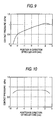
- Fig. 9 shows a result of calculating a state of distributing the contact pressure between the roller and the track in a direction of a roller axis. Running life of a total of the linear guide apparatus is significantly dependent on running life of a portion of the roller at which the contact pressure is the largest. That is, when there is a deviation in the distribution of the contact pressure as shown by Fig.
- a face pressure of a portion of the roller is abnormally increased to thereby shorten the life of the total of the linear guide apparatus. Further, when the roller is brought into an uneven contact state in this way, there is a concern of effecting an influence on an attitude of the rolling roller.
- the liner guide apparatus comprising:
- the linear guide apparatus comprising:
- a basic constitution of a linear guide apparatus of the embodiment is similar to that of the related art.
- a slider 2 substantially in a U-like shape rides over a guide rail 1 and is made to be movable along the guide rail 1 relatively thereto.
- Left and right side faces of the guide rail 1 are formed with a total of four tracks of respective two tracks of guide rail side track faces 3, 4.
- slider side track faces 5, 6 are formed at positions of inner peripheral portions of leg portions of the slider 2 opposedly to the respective guide rail side track faces 3, 4.
- Notation 7 designates a rolling element return path.
- a plurality of cylindrical rollers 8 are arranged on load rolling paths comprising the guide rail side track faces 3, 4 and the slider side track faces 5, 6 opposed to each other along the load rolling path with a predetermined preload. In the case of being operated, the cylindrical rollers 8 are rolled on the load rolling paths.
- both of the upper side track face 5 and the lower side track face 6 are brought into a state that they pivot by a predetermined angle in a counterclockwise direction relative to positions of the track faces under no load.
- the upper side back face 3 is brought into a state that it pivots by a predetermined angle in a counterclockwise direction relative to the position of the track face under no load.
- the lower side track face 4 is hardly changed by presence or absence of the preload. Further, the guide rail side track faces 3, 4 in the no load state are set to reference track faces constituting references as in the related art.
- the track faces 5, 6 are worked into faces which are inclined by predetermined initial inclined angles relative to reference track faces constituting a reference as shown in Fig. 2. That is, the upper side track face 5 is worked into a face inclined relative to a reference track face (not illustrated) by an initial inclined angle, which cancels amounts of inclinations of both of the guide rail side track face 3 and the slider side track face 5 due to deformation.
- the lower side track face 6 is worked into a face inclined relative to a reference track face (a face designated by notation 6A) by an initial inclined angle, which cancels an amount of inclination produced by deforming a member of the slider side trace face 5.
- the amounts of inclinations by the elastic deformation from the reference track faces in the no load state may be calculated by an analysis of a finite element method or the like or may be provided by an experiment.
- initial inclined angle K1 ⁇ (preload) + K2 where notations K1, K2 are coefficients.
- the inclined angle may be determined by adding also elastic deformation by an external load produced by a self weight of the slider 2 per se or an object or the like attached to the slider 2.
- an object to be guided (machine apparatus) is normally attached to an upper face of the slider 2 and therefore, the object to be guided is operated to restrain deformation of an upper face of the horizontal portion of the slider 2 as shown by Figs. 5B through 5C and under a normal condition of use, a rate of contributing to deformation of the track faces by the external load is small. Therefore, in order to determine the initial inclined angle, generally, when a consideration is given to only the preload, the constitution is sufficient. Naturally, a further ideal initial inclined angle may be calculated by taking a consideration also to the external load.
- the embodiment is not limited thereto.
- Only the guide rail side track faces 3, 4 may be inclined from the reference track faces or the guide rail side track faces 3, 4 and the slider side track faces 5, 6 may respectively be distributed with inclinations by a predetermined distributing rate to thereby incline the both from the reference track faces to thereby cancel the respective inclined amounts from the faces under no load by loading the preload to the guide rail side track faces 3, 4 and the slider side track faces 5, 6.
- the guide rail side track faces 3, 4 and the slider side track faces 5, 6 may be worked respectively to faces inclined relative to individual reference track faces constituting a target determined by design or the like (inclination in a direction reverse to inclination by deformation) under a no load state before interposing the roller 8 to thereby cancel amounts of inclinations produced by elastic deformation of a member (slider 2 or guide rail 1) by loading the preload in interposing the roller 8. Also thereby, in the state of loading the preload, the guide rail side track faces 3, 4 and the slider side track faces 5, 6 opposed to each other are in parallel with each other or substantially in parallel with each other and the deviations in the contact face pressures between the respective track faces and the roller can be restrained in the state of interposing the roller 8. Further, in the case, the respective target reference track faces can be constituted by the respective track faces when the rollers 8 are interposed and therefore, there is also achieved an effect of capable of constituting a desired inclination by the inclination of the interposed rollers.
- the side of the slider side track faces 5, 6 is inclined by the predetermined initial inclined angle to cancel the amounts of inclinations by deformation respectively produced at the guide rail side track faces 3, 4 and the slider side track faces 5, 6.
- the initial inclined angle is determined as follows.
- the roller 8 is applied with a preload.
- the preload is set to 8000N.
- the slider 2 is operated with a downward load of 5000N as the self weight.
- a state of deforming the slider 2 and the guide rail 1 when the preload is operated can be calculated by a publicly-known analysis method of an FEM analysis or the like.
- Fig. 5B is a view of a result of calculating the deformation of the member of the slider 2 by an FEM analysis.
- the initial inclined angles of the slider side track faces 5, 6 disregarding deformation of the side of the guide rail 1 may be constituted by 6.8 ⁇ 10 -4 rad (a direction of the initial inclined angle is reverse to a direction inclined by deformation) both in the upper side and the lower side members.
- a total of the leg portions is deformed to integrally open and therefore, the amounts of inclinations of the upper side track face and the lower side track face by deforming the members are substantially the same value.
- the inclined angle is calculated by the FEM analysis
- the both substantially coincide with each other.
- the both substantially coincide with each other similarly. Therefore, the amount of deforming the slider 2 can be predicted by calculation by the finite element method with excellent accuracy. From the result, also with regard to an amount of inclination of the track face by deforming the member, the both may be regarded to coincide with each other by experiment and analysis with sufficient accuracy.
- the FEM analysis is utilized, an initial inclined angle relative to the reference track face can be determined without trial fabrication and measurement of a product. Therefore, a time period and cost for trial fabrication and measurement can be reduced.
- the initial inclined angle relative to the reference track face is determined by calculating the initial inclined angle by the FEM analysis also with regard to deformation of the member on the side of the guide rail 1.
- the condition is the same as the above-described.
- amounts of inclination of the upper side track face and the lower side track face by deforming the members are respectively +1.1 ⁇ 10 -4 rad on the upper side and -0.1 ⁇ 10 -4 rad on the lower side (clockwise direction is positive as sign).
- the amount of inclination on the side of the guide rail 1 may be dealt with by inclining the track faces on the side of the guide rail 1 from the reference track faces, or the slider side track face 5, 6 opposed thereto may be inclined from the reference track faces by adding also the amounts of inclinations on the side of the guide rail 1.
- the initial inclined angles of the upper side track face and the lower side track face differ from each other and therefore, working is carried out by inclining, for example, a shaping grindstone individually such that the track faces are inclined by the respective initial inclined angles from the reference track faces by a unit of each track face, or working is carried out by using a shaping grindstone formed by a rotary dresser having different inclined angles for the upper and lower track faces.
- the initial inclined angles of the upper and lower track faces maybe set to 6.3 ⁇ 10 -4 rad by taking an average of the both. Even by setting in this way, the deviation in the contact face pressure distribution between the roller 8 and the track face is alleviated.
- Comparative Example 1 by the related art is used.
- Comparative Example 1 in a state in which the preload is not applied, the track faces of the guide rail 1 and the slider 2 are in parallel with each other constituting inclinations equal to those of reference trace faces constituting a target. Otherwise, dimensions of the linear guide apparatus of Example 1 and Comparative Example, 1 are the same.
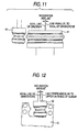
- Two track faces disposed at the inner peripheral faces of the leg portions of the slider 2 are simultaneously worked by using a shaping grindstone 40.
- an outer peripheral face of the shaping grindstone 40 is formed by a rotary dresser 41 accuracy of which is correctly controlled to a shape of finishing the inner peripheral faces of the leg portions of the slider 2 (shapes of track faces are set by inclinations of reference track faces).
- a face in correspondence with the track face constituting the inclination of the reference track face is transcribed to the grindstone 40 by making a shaft of the rotary dresser 41 and a rotating shaft of the grindstone 40 in parallel with each other and pressing the outer periphery of the grindstone 40 to the rotary dresser 41 to form.
- the outer periphery of the grindstone 40 is pressed to the rotary dresser 41 to form by bringing the shaft of the rotary dresser 41 into a state of being inclined thereto by the initial inclined angle.
- the grindstone 40 is transcribed with the face in correspondence with the track face inclined to the reference track face by the initial inclined angle.
- the rotating shaft of the shaping grindstone may be inclined by the initial inclined angle to form.
- the inclined angle is, for example, 6.8 ⁇ 10 -4 rad in the case of Example 1.
- both of the upper side track face and the lower side track face are worked to finish to the track faces inclined from the reference inclined angles by the initial inclined angles.
- the face of the shaping grindstone 40 is formed in the shape of the face in correspondence with the track faces inclined from the reference track faces by the initial inclined angles, the embodiment is not limited thereto.
- the shaping grindstone 40 is formed by making the shaft of the rotary dresser 41 and the rotating shaft of the shaping grindstone 40 inparallel with each other, the grindstone 40 is transcribed with the face in correspondence with the track faces constituting the inclinations of the reference track faces. Further, in working to finish the inner peripheral faces of the leg portions on the slider side 2, as shown by Fig. 12 and Fig. 13, the rotating shaft of the shaping grindstone 40 or a work (slider 2) is inclined by the initial inclined angle.
- both of the two upper and lower track faces on the leg portion of the slider 2 on one side can be worked to the track faces inclined to the reference track faces by the desirable initial inclined angles.
- the upper side track face is worked to the track face inclined from the reference track face by the initial inclined angle by similar working.
- a first measuring method is a method of measuring the shape of the left and right track faces of either one of the upper side and the lower side track faces.
- the left and right track faces are measured by a shape measuring instrument by bringing a measuring probe 31 into a supportable state by hanging a connecting member 30 comprising a paper piece or the like to span the left and right leg portions 2A.
- the initial inclined angle is provided by an angle constituted by the left and right track faces.
- the shape of the dresser can be ensured with high accuracy. Therefore, when the required initial inclined angle is provided to the lower side track face, also the upper side track face may be regarded to be provided with the required initial inclined angle.
- Fig. 7 shows a second measuring method.
- measuring rollers 32 are brought into contact with recess portions respectively constituted by the track faces and flange portions and distances W1 and W2 between the left and right rollers 32 are measured.
- a distance between the upper and lower rollers 32 is designated by notation h
- the flange portions are constituted only at the track faces on the side of the slider 2. Therefore, it is convenient for the linear guide apparatus of the type that the inclinations are provided only by the track faces on the side of the slider 2.
- the shape of dresser becomes complicated and cost is increased. Therefore, it is preferable to provide the flange portion to only one of the slider 2 or the guide line 1. Further, it is preferable to provide the inclined angles only to the member provided with the flange portions.
Landscapes
- Engineering & Computer Science (AREA)
- General Engineering & Computer Science (AREA)
- Mechanical Engineering (AREA)
- Bearings For Parts Moving Linearly (AREA)
- Rolling Contact Bearings (AREA)
- Support Of The Bearing (AREA)
Applications Claiming Priority (2)
| Application Number | Priority Date | Filing Date | Title |
|---|---|---|---|
| JP2003118895 | 2003-04-23 | ||
| JP2003118895A JP2004324737A (ja) | 2003-04-23 | 2003-04-23 | リニアガイド装置 |
Publications (2)
| Publication Number | Publication Date |
|---|---|
| EP1471273A2 true EP1471273A2 (de) | 2004-10-27 |
| EP1471273A3 EP1471273A3 (de) | 2009-10-28 |
Family
ID=32959639
Family Applications (1)
| Application Number | Title | Priority Date | Filing Date |
|---|---|---|---|
| EP04009733A Withdrawn EP1471273A3 (de) | 2003-04-23 | 2004-04-23 | Linearführungseinheit |
Country Status (3)
| Country | Link |
|---|---|
| US (1) | US6979126B2 (de) |
| EP (1) | EP1471273A3 (de) |
| JP (1) | JP2004324737A (de) |
Cited By (2)
| Publication number | Priority date | Publication date | Assignee | Title |
|---|---|---|---|---|
| EP2604875A4 (de) * | 2011-09-07 | 2015-07-29 | Nsk Ltd | Führungsvorrichtung für linearbewegungen |
| GB2560727A (en) * | 2017-03-22 | 2018-09-26 | Accuride Int Ltd | An adjustable bearing assembly |
Families Citing this family (3)
| Publication number | Priority date | Publication date | Assignee | Title |
|---|---|---|---|---|
| JP4435104B2 (ja) * | 2006-03-29 | 2010-03-17 | 日本トムソン株式会社 | 直動案内ユニットおよび直動案内ユニットの荷重判別方法 |
| JP2007298120A (ja) * | 2006-04-28 | 2007-11-15 | Nsk Ltd | 直動案内装置用スライダ、直動案内装置および直動案内装置用スライダの製造方法、並びに、搬送装置用可動部材および搬送装置 |
| KR102836684B1 (ko) * | 2018-11-27 | 2025-07-21 | 티에치케이 가부시끼가이샤 | 운동 안내 장치 |
Citations (1)
| Publication number | Priority date | Publication date | Assignee | Title |
|---|---|---|---|---|
| JPH05280537A (ja) | 1992-03-31 | 1993-10-26 | Nippon Thompson Co Ltd | 転がり案内ユニット |
Family Cites Families (10)
| Publication number | Priority date | Publication date | Assignee | Title |
|---|---|---|---|---|
| US4496197A (en) * | 1983-04-11 | 1985-01-29 | The Bendix Corporation | Linear motion bearing truck and rail assembly |
| JPS59219518A (ja) * | 1983-05-26 | 1984-12-10 | Hiroshi Teramachi | 直線摺動用ロ−ラ−ベアリングユニツト |
| JPS6025628A (ja) * | 1983-07-20 | 1985-02-08 | Hiroshi Teramachi | 直線摺動用テ−ブルアツセンブリ |
| JPS6196213A (ja) * | 1984-10-16 | 1986-05-14 | Hiroshi Teramachi | 直線摺動用ロ−ラ−ベアリング |
| JPS6188017A (ja) * | 1984-09-21 | 1986-05-06 | Hiroshi Teramachi | 直線摺動用ロ−ラ−ベアリング |
| JPS61100337A (ja) * | 1984-10-23 | 1986-05-19 | Hiroshi Teramachi | 直線案内装置 |
| JPS6196215A (ja) * | 1984-10-16 | 1986-05-14 | Hiroshi Teramachi | 直線摺動用ロ−ラ−ベアリング及び直線案内装置 |
| US5005988A (en) * | 1990-03-28 | 1991-04-09 | Thomson Industries, Inc. | Linear motion bearing |
| JP3751101B2 (ja) * | 1995-12-28 | 2006-03-01 | Thk株式会社 | 直線ロ−ラ案内装置 |
| JP4479066B2 (ja) * | 2000-06-23 | 2010-06-09 | 日本精工株式会社 | 転がり案内ユニット |
-
2003
- 2003-04-23 JP JP2003118895A patent/JP2004324737A/ja active Pending
-
2004
- 2004-04-23 EP EP04009733A patent/EP1471273A3/de not_active Withdrawn
- 2004-04-23 US US10/830,024 patent/US6979126B2/en not_active Expired - Lifetime
Patent Citations (1)
| Publication number | Priority date | Publication date | Assignee | Title |
|---|---|---|---|---|
| JPH05280537A (ja) | 1992-03-31 | 1993-10-26 | Nippon Thompson Co Ltd | 転がり案内ユニット |
Cited By (3)
| Publication number | Priority date | Publication date | Assignee | Title |
|---|---|---|---|---|
| EP2604875A4 (de) * | 2011-09-07 | 2015-07-29 | Nsk Ltd | Führungsvorrichtung für linearbewegungen |
| GB2560727A (en) * | 2017-03-22 | 2018-09-26 | Accuride Int Ltd | An adjustable bearing assembly |
| GB2560727B (en) * | 2017-03-22 | 2020-06-17 | Accuride Int Ltd | An adjustable bearing assembly |
Also Published As
| Publication number | Publication date |
|---|---|
| JP2004324737A (ja) | 2004-11-18 |
| US6979126B2 (en) | 2005-12-27 |
| US20040240757A1 (en) | 2004-12-02 |
| EP1471273A3 (de) | 2009-10-28 |
Similar Documents
| Publication | Publication Date | Title |
|---|---|---|
| KR100687310B1 (ko) | 금속 판재의 압연 방법 및 압연 장치 | |
| CN101238297B (zh) | 线性导引装置 | |
| US6151791A (en) | Method for measuring roll profile | |
| US6979126B2 (en) | Linear guide apparatus | |
| JPS6211208B2 (de) | ||
| JPH10501470A (ja) | 多重ロール式プラニッシャーと、その利用 | |
| CA2667800A1 (en) | Rolling method and rolling apparatus for flat-rolled metal materials | |
| DE60108691T2 (de) | Vorrichtung und Verfahren zum Ausrichten eines Spiralverdichters | |
| US5248202A (en) | Bearing and a table for linear sliding motion | |
| US5092720A (en) | Method for determination of longitudinal and profile modification of tool gear tooth surface | |
| KR100216299B1 (ko) | 6단 압연기 | |
| GB2142098A (en) | Linear bearing | |
| EP1310689B1 (de) | Linearlagerführung | |
| JP4704577B2 (ja) | 転がり案内装置および転がり案内装置システム | |
| JPS59152062A (ja) | 調整といし車のためのドレッシング装置 | |
| US6408666B1 (en) | Rolling mill and rolling method | |
| JPH06323332A (ja) | 転がり案内装置 | |
| TWI476328B (zh) | Rolling guide device | |
| JPWO2005010384A1 (ja) | 偏荷重防止機構を備えた直線案内装置 | |
| JP4257448B2 (ja) | ローラ案内装置 | |
| JP4932769B2 (ja) | 圧延機の零調方法 | |
| JP5182034B2 (ja) | 圧延機の主圧下変形特性同定方法 | |
| JP3446641B2 (ja) | 圧延機および圧延方法 | |
| JP2650535B2 (ja) | 圧延ロール研削方法 | |
| JPS5930488B2 (ja) | オフセツト方式によるフランジ厚の異なる形鋼のユニバ−サル圧延法 |
Legal Events
| Date | Code | Title | Description |
|---|---|---|---|
| PUAI | Public reference made under article 153(3) epc to a published international application that has entered the european phase |
Free format text: ORIGINAL CODE: 0009012 |
|
| AK | Designated contracting states |
Kind code of ref document: A2 Designated state(s): AT BE BG CH CY CZ DE DK EE ES FI FR GB GR HU IE IT LI LU MC NL PL PT RO SE SI SK TR |
|
| AX | Request for extension of the european patent |
Extension state: AL HR LT LV MK |
|
| PUAL | Search report despatched |
Free format text: ORIGINAL CODE: 0009013 |
|
| AK | Designated contracting states |
Kind code of ref document: A3 Designated state(s): AT BE BG CH CY CZ DE DK EE ES FI FR GB GR HU IE IT LI LU MC NL PL PT RO SE SI SK TR |
|
| AX | Request for extension of the european patent |
Extension state: AL HR LT LV MK |
|
| AKX | Designation fees paid | ||
| STAA | Information on the status of an ep patent application or granted ep patent |
Free format text: STATUS: THE APPLICATION IS DEEMED TO BE WITHDRAWN |
|
| 18D | Application deemed to be withdrawn |
Effective date: 20100429 |
|
| REG | Reference to a national code |
Ref country code: DE Ref legal event code: 8566 |