EP1471276A2 - Joint universel avec joint d'étanchéité pour vider des gaz - Google Patents
Joint universel avec joint d'étanchéité pour vider des gaz Download PDFInfo
- Publication number
- EP1471276A2 EP1471276A2 EP04101339A EP04101339A EP1471276A2 EP 1471276 A2 EP1471276 A2 EP 1471276A2 EP 04101339 A EP04101339 A EP 04101339A EP 04101339 A EP04101339 A EP 04101339A EP 1471276 A2 EP1471276 A2 EP 1471276A2
- Authority
- EP
- European Patent Office
- Prior art keywords
- bearing cup
- trunnion
- universal joint
- lip
- seal
- Prior art date
- Legal status (The legal status is an assumption and is not a legal conclusion. Google has not performed a legal analysis and makes no representation as to the accuracy of the status listed.)
- Granted
Links
Images



Classifications
-
- F—MECHANICAL ENGINEERING; LIGHTING; HEATING; WEAPONS; BLASTING
- F16—ENGINEERING ELEMENTS AND UNITS; GENERAL MEASURES FOR PRODUCING AND MAINTAINING EFFECTIVE FUNCTIONING OF MACHINES OR INSTALLATIONS; THERMAL INSULATION IN GENERAL
- F16D—COUPLINGS FOR TRANSMITTING ROTATION; CLUTCHES; BRAKES
- F16D3/00—Yielding couplings, i.e. with means permitting movement between the connected parts during the drive
- F16D3/84—Shrouds, e.g. casings, covers; Sealing means specially adapted therefor
-
- F—MECHANICAL ENGINEERING; LIGHTING; HEATING; WEAPONS; BLASTING
- F16—ENGINEERING ELEMENTS AND UNITS; GENERAL MEASURES FOR PRODUCING AND MAINTAINING EFFECTIVE FUNCTIONING OF MACHINES OR INSTALLATIONS; THERMAL INSULATION IN GENERAL
- F16C—SHAFTS; FLEXIBLE SHAFTS; ELEMENTS OR CRANKSHAFT MECHANISMS; ROTARY BODIES OTHER THAN GEARING ELEMENTS; BEARINGS
- F16C21/00—Combinations of sliding-contact bearings with ball or roller bearings, for exclusively rotary movement
- F16C21/005—Combinations of sliding-contact bearings with ball or roller bearings, for exclusively rotary movement the external zone of a bearing with rolling members, e.g. needles, being cup-shaped, with or without a separate thrust-bearing disc or ring, e.g. for universal joints
-
- F—MECHANICAL ENGINEERING; LIGHTING; HEATING; WEAPONS; BLASTING
- F16—ENGINEERING ELEMENTS AND UNITS; GENERAL MEASURES FOR PRODUCING AND MAINTAINING EFFECTIVE FUNCTIONING OF MACHINES OR INSTALLATIONS; THERMAL INSULATION IN GENERAL
- F16C—SHAFTS; FLEXIBLE SHAFTS; ELEMENTS OR CRANKSHAFT MECHANISMS; ROTARY BODIES OTHER THAN GEARING ELEMENTS; BEARINGS
- F16C33/00—Parts of bearings; Special methods for making bearings or parts thereof
- F16C33/72—Sealings
- F16C33/76—Sealings of ball or roller bearings
- F16C33/78—Sealings of ball or roller bearings with a diaphragm, disc, or ring, with or without resilient members
- F16C33/7803—Sealings of ball or roller bearings with a diaphragm, disc, or ring, with or without resilient members suited for particular types of rolling bearings
- F16C33/7809—Sealings of ball or roller bearings with a diaphragm, disc, or ring, with or without resilient members suited for particular types of rolling bearings for needle roller bearings
-
- F—MECHANICAL ENGINEERING; LIGHTING; HEATING; WEAPONS; BLASTING
- F16—ENGINEERING ELEMENTS AND UNITS; GENERAL MEASURES FOR PRODUCING AND MAINTAINING EFFECTIVE FUNCTIONING OF MACHINES OR INSTALLATIONS; THERMAL INSULATION IN GENERAL
- F16D—COUPLINGS FOR TRANSMITTING ROTATION; CLUTCHES; BRAKES
- F16D3/00—Yielding couplings, i.e. with means permitting movement between the connected parts during the drive
- F16D3/16—Universal joints in which flexibility is produced by means of pivots or sliding or rolling connecting parts
- F16D3/26—Hooke's joints or other joints with an equivalent intermediate member to which each coupling part is pivotally or slidably connected
- F16D3/38—Hooke's joints or other joints with an equivalent intermediate member to which each coupling part is pivotally or slidably connected with a single intermediate member with trunnions or bearings arranged on two axes perpendicular to one another
- F16D3/382—Hooke's joints or other joints with an equivalent intermediate member to which each coupling part is pivotally or slidably connected with a single intermediate member with trunnions or bearings arranged on two axes perpendicular to one another constructional details of other than the intermediate member
- F16D3/385—Bearing cup; Bearing construction; Bearing seal; Mounting of bearing on the intermediate member
-
- F—MECHANICAL ENGINEERING; LIGHTING; HEATING; WEAPONS; BLASTING
- F16—ENGINEERING ELEMENTS AND UNITS; GENERAL MEASURES FOR PRODUCING AND MAINTAINING EFFECTIVE FUNCTIONING OF MACHINES OR INSTALLATIONS; THERMAL INSULATION IN GENERAL
- F16C—SHAFTS; FLEXIBLE SHAFTS; ELEMENTS OR CRANKSHAFT MECHANISMS; ROTARY BODIES OTHER THAN GEARING ELEMENTS; BEARINGS
- F16C19/00—Bearings with rolling contact, for exclusively rotary movement
- F16C19/22—Bearings with rolling contact, for exclusively rotary movement with bearing rollers essentially of the same size in one or more circular rows, e.g. needle bearings
- F16C19/44—Needle bearings
- F16C19/46—Needle bearings with one row or needles
- F16C19/466—Needle bearings with one row or needles comprising needle rollers and an outer ring, i.e. subunit without inner ring
-
- F—MECHANICAL ENGINEERING; LIGHTING; HEATING; WEAPONS; BLASTING
- F16—ENGINEERING ELEMENTS AND UNITS; GENERAL MEASURES FOR PRODUCING AND MAINTAINING EFFECTIVE FUNCTIONING OF MACHINES OR INSTALLATIONS; THERMAL INSULATION IN GENERAL
- F16C—SHAFTS; FLEXIBLE SHAFTS; ELEMENTS OR CRANKSHAFT MECHANISMS; ROTARY BODIES OTHER THAN GEARING ELEMENTS; BEARINGS
- F16C2361/00—Apparatus or articles in engineering in general
- F16C2361/41—Couplings
-
- F—MECHANICAL ENGINEERING; LIGHTING; HEATING; WEAPONS; BLASTING
- F16—ENGINEERING ELEMENTS AND UNITS; GENERAL MEASURES FOR PRODUCING AND MAINTAINING EFFECTIVE FUNCTIONING OF MACHINES OR INSTALLATIONS; THERMAL INSULATION IN GENERAL
- F16D—COUPLINGS FOR TRANSMITTING ROTATION; CLUTCHES; BRAKES
- F16D2300/00—Special features for couplings or clutches
- F16D2300/08—Details or arrangements of sealings not provided for in group F16D3/84
-
- F—MECHANICAL ENGINEERING; LIGHTING; HEATING; WEAPONS; BLASTING
- F16—ENGINEERING ELEMENTS AND UNITS; GENERAL MEASURES FOR PRODUCING AND MAINTAINING EFFECTIVE FUNCTIONING OF MACHINES OR INSTALLATIONS; THERMAL INSULATION IN GENERAL
- F16D—COUPLINGS FOR TRANSMITTING ROTATION; CLUTCHES; BRAKES
- F16D3/00—Yielding couplings, i.e. with means permitting movement between the connected parts during the drive
- F16D3/16—Universal joints in which flexibility is produced by means of pivots or sliding or rolling connecting parts
- F16D3/26—Hooke's joints or other joints with an equivalent intermediate member to which each coupling part is pivotally or slidably connected
- F16D3/38—Hooke's joints or other joints with an equivalent intermediate member to which each coupling part is pivotally or slidably connected with a single intermediate member with trunnions or bearings arranged on two axes perpendicular to one another
- F16D3/40—Hooke's joints or other joints with an equivalent intermediate member to which each coupling part is pivotally or slidably connected with a single intermediate member with trunnions or bearings arranged on two axes perpendicular to one another with intermediate member provided with two pairs of outwardly-directed trunnions on intersecting axes
- F16D3/41—Hooke's joints or other joints with an equivalent intermediate member to which each coupling part is pivotally or slidably connected with a single intermediate member with trunnions or bearings arranged on two axes perpendicular to one another with intermediate member provided with two pairs of outwardly-directed trunnions on intersecting axes with ball or roller bearings
-
- Y—GENERAL TAGGING OF NEW TECHNOLOGICAL DEVELOPMENTS; GENERAL TAGGING OF CROSS-SECTIONAL TECHNOLOGIES SPANNING OVER SEVERAL SECTIONS OF THE IPC; TECHNICAL SUBJECTS COVERED BY FORMER USPC CROSS-REFERENCE ART COLLECTIONS [XRACs] AND DIGESTS
- Y10—TECHNICAL SUBJECTS COVERED BY FORMER USPC
- Y10T—TECHNICAL SUBJECTS COVERED BY FORMER US CLASSIFICATION
- Y10T29/00—Metal working
- Y10T29/49—Method of mechanical manufacture
- Y10T29/49826—Assembling or joining
Definitions
- the present invention generally relates to a universal joint for use in a driveline of a motor vehicle. More specifically, the present invention pertains to a universal joint equipped with a mechanism for securing a bearing cup assembly to a cruciform trunnion.
- universal joints are used in motor vehicle driveline applications for interconnecting a pair of rotary shafts and permitting changes in angular ity therebetween.
- Many conventional universal joints include a pair of bifurcated yokes which are secured to the rotary shafts.
- the bifurcated yokes are interconnected by a spider or a cruciform for rotation about independent axes.
- the cruciform include s four orthogonal trunnions with each opposing pair of axially aligned trunnions mounted in a pair of aligned bores formed in the bifurcated yokes.
- a bearing cup is secured in each bore and a bearing assembly is retained in the bearing cup such that each yoke is supported for pivotal movement relative to one of the pairs of trunnions.
- a thrust washer between the trunnion and the bearing cup to absorb the radially -directed thrust forces which may occur therebetwee n.
- each bearing assembly includes a seal coupled to a bearing cup which engages a portion of the trunnion.
- air and grease are sometimes trapped within the bearing cup. The pressure can cause the bearing assembly to be misaligned or to become improperly positioned after the installation force is removed. Possible bearing contamination and loss of productivity may result.
- the bearing cup assemblies must be removed and re -installed requiring expense of time and cost. Accordingly, it would be advantageous to provide a universal joint having bearing cup assemblies which allow trapped air and grease to be purged during installation without compromising the integrity of the bearing cup to trunnion seal.
- the present invention is directed to a universal joint for interconnecting a pair of rotating sh afts.
- the universal joint includes a pair of bifurcated yokes interconnected by a cruciform.
- the cruciform includes four orthogonal trunnions each including a lubricant passage.
- a seal includes a plurality of protrusions engaging a portion of the trunnion to provide a purging path for trapped air.
- the present invention is directed to a universal joint of the type used in motor vehicle driveline applications for interconnecting rotating shafts in a manner permitting changes in angularity therebetween.
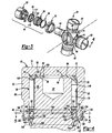
- a universal joint 10 is shown connecting a first shaft 12 to a second shaft 14.
- universal joint 10 includes a first yoke 16 attached to an end of first shaft 12, a second yoke 18 attached to an end of second shaft 14 and a cruciform 20 interconnecting first yoke 16 to second yoke 18.
- the first yoke 16 is bifurcated and includes a pair of laterally -spaced legs 22 which are preferably symmetr ical with respect to the rotary axis of first shaft 12, as denoted by construction line "A".
- Legs 22 include an inboard surface 24 and an outboard surface 26 with a journal 27 extending therebetween.
- Apertures 28 are formed by coupling a pair of end caps 30 to legs 22 via fasteners 31. End caps 30 cooperate with joumals 27 to complete apertures 28. Apertures 28 are aligned on a first trunnion axis, as denoted by construction line "Y", which passes through and is orthogonal with respect to rotary axis " A" of first shaft 12.
- Second yoke 18 is bifurcated and includes a pair of laterally -spaced legs 32 which are preferably symmetrical with respect to the rotary axis of second shaft 14, as denoted by construction line "B".
- Legs 32 include an inboard surfa ce 34 and an outboard surface 36 with an aperture 38 extending therebetween.
- Apertures 38 are aligned on a second trunnion axis, as denoted by construction line “Z”, which passes through and is orthogonal with respect to rotary axis "B" of second shaft 1 4.
- Apertures 38 are throughbores which include an annular groove 40 formed between the inboard surface 34 and the outboard surface 36.
- the shape and dimensions of apertures 28 and 38 may either be identical or different depending on the particular dimensions of cruciform 20 used therewith.
- the annular ring groove 40 may be formed by machining, casting or by similar technique.
- cruciform 20 includes a central hub 42 from which a pair of first trunnions 44 and a pair of second trunnions 46 extend.
- First trunnions 44 are orthogonal with respect to second trunnions 46.
- First trunnions 44 are adapted for insertion into apertures 28 in legs 22 of first yoke 16 so as to be axially al igned on first trunnion axis "Y”.
- second trunnions 46 are adapted to be inserted into apertures 38 in legs 32 of second yoke 18 so as to be axially aligned on second trunnion axis "Z".
- trunnion axes "Y" and "Z” pass through a common plane "C" which orthogonally intersects the rotary axis of cruciform 20, as shown in Figure 1.
- Universal joint 10 also includes a first pair of bearing cup assemblies 48 adapted to be mounted in apertures 28 and a second pair of bearing cup assemblies 50 adapted to be mounted in apertures 38.
- First bearing cup assemblies 48 are provided for receiving and rotatably supporting first trunnions 44 in apertures 2 8.
- second bearing cup assemblies 50 are provided for receiving and rotatably supporting second trunnions 46 in apertures 38.
- first bearing cup assemblies 4 8 With the understanding that the corresponding components of second bearing cup assemblies 50 are substantially identical.
- Bearing cup 52 is substantially hollow and cylindrical in shape.
- Bearing cup 52 includes a substantially cylindrical tubular segment 62 closed at one end by an end segment 64.
- Tubular segment 62 includes an outer wa II surface 66 and an inner wall surface 68.
- End segment 64 includes an outer surface 70 and an inner surface 72.
- Roller bearings 56 are positioned between inner wall surface 68 and an outer wall surface 74 of trunnion 44 to allow relative rotary movemen t between bearing cup 52 and trunnion 44.
- Roller bearings 56 are oriented to rotate on an axis parallel to axis "Y" of trunnions 44 and are arranged in a circumferential array about this axis. One end of each roller bearing 56 is supported to roll agains t the bearing surface 76 formed on a circumferential flange segment 78 of thrust washer 54. The opposite ends of roller bearings 56 are captured by seal washer 58 which, in turn, is retained by seal 60. Seal 60 extends between outer wall surface 66 of be aring cup 52 and outer wall surface 74 of trunnion 44 to protect roller bearings 56 from contamination and to retain lubricant within bearing cup assembly 48.
- thrust washer 54 includes a disk segment 82 from which circumfe rential flange 78 extends.
- a central aperture 86 extends through disk segment 82 and is in communication with a lubricant passage 92 found in each trunnion.
- a fitting (not shown) mounted on central hub 42 of cruciform 20 communicates with lubricant pass age 92. The fitting is used to supply lubricant to passage 92 for lubricating roller bearings 56 as well as for providing a lubricant film between relatively moveable surfaces.
- Disk segment 82 has an outer face surface 96 which faces and contacts inner surface 72 of bearing cup 52. Disk segment 82 also includes an inner face surface 98 which faces and contacts an end surface 100 of trunnion 44. Inner face surface 98 and outer face surface 96 are substantially parallel such that disk segment 82 has a co nstant thickness.
- thrust washer 54 includes a circumferential inner wall surface 102 and a circumferential outer wall surface 104, as defined by flange segment 78. Circumferential inner wall surface 102 is adapted to face outer wall surface 74 of trunnion 44. Circumferential outer wall surface 104 faces inner wall surface 68 of bearing cup 52. As such, thrust washer 54 functions to align bearing cup 52 and trunnion 44.
- Thrust washer 54 includes a series of lubrication grooves 112 which extend radially from central aperture 86 to circumferential inner wall surface 102 of flange segment 78.
- Grooves 112 are arcuate in profile to define a cylindrical wall surface. It is preferable that an odd number of grooves 112 are provided and which are eq ually spaced to define a like number of pie -shaped portions of disk segment 82.
- a plurality of indentations or dimples 114 are formed on the pie -shaped portions of disk segment 82. Dimples 114 can be randomly oriented or, more preferably, be aligned to define two circumferential rows.
- Dimples 114 are adapted to retain lubricant therein to provide continuous lubrication over a large area of trunnion end surface 100. In addition, dimples 114 allow contaminants to be removed from the operating surfaces and be collected therein. Thrust washer 54 is constructed from a resilient material such as injection molded plastic.
- Figures 4-6 depict seal 60 including a case 120 and an elastomer 122 bonded to case 120.
- Case 120 is preferably constructed from a mild steel.
- Elastomer 122 is preferably constructed from an injection moldable compound which is resilient and resistant to degradation from exposure to oil, grease, ozone or other commonly present compounds.
- Case 120 is a generally cup -shaped member formed from a steel sheet having a substantially constant thickness.
- Case 120 includes an outer wall 124, an end wall 126, an inner wall 128, and an inner flange 130.
- Inner flange 130 terminates at a first edge 132.
- Outer wall 124 terminates at a se cond edge 134.
- Case 120 includes an inner surface 136 extending from first edge 132 to second edge 134.
- An outer surface 138 is positioned on the opposite side of case 120 from inner surface 136 and also extends from first edge 132 to second edge 134.
- E lastomer 122 is bonded to outer surface 138 and extends from
- Elastomer 122 includes a first lip 140, a second lip 142 and a third lip 144.
- First lip 140 functions as a primary seal and engages trunnion 44 at a seal race portion 146.
- Figure 4 depicts seal race portion 146 having a greater outer diameter than a bearing support portion 148.
- seal race portion 146 may be sized and shaped identically as bearing support portion 148 without departing from the scope of the present invention.
- First lip 140 is sized to nominally interfere with seal race portion 146. Because elastomer 122 is constructed from a resilient material, first lip 140 biasedly engages seal race portion 146.
- a plurality of projections 149 extend radially inwardly from a contact surface 150 of first lip 140.
- Projections 149 are sized and shaped to cause localized openings 151 to be formed between contact surface 150 and seal race portion 146 of trunnion 44.
- the openings 151 between first lip 140 and seal race portion 146 form passages for trapped air and/or grease to escape during installation of bearing cup assembly 48. It should be appreciated that while projections 149 provide openings for the purging of tra pped air and grease at initial installation, the projections are sized to wear rapidly. Once projections 149 wear, the openings 151 between contact surface 150 and seal race portion 146 close to provide a desirable seal between first lip 140 and seal race portion 146.
- Second lip 142 is shaped as a wiper 152 extending from a body 154 of elastomer 122. Wiper 152 extends from body 154 at an angle such that pressurized air and grease within bearing cup 52 may escape once passed first lip 140. However, should second lip 142 provide a greater pressurizing function, wiper 152 may also be equipped with a plurality of projections (not shown) to provide local openings to assist in purging trapped air and grease.
- Third lip 144 includes a wiper 156 radially inwardly extending from body 154.
- Wiper 152 and wiper 156 are constructed to biasedly engage seal race portion 146 once positioned on trunnion 44.
- wiper 156 deflects from an unloaded position depicted in phantom line representation at 156' t o the biasedly engaged position shown in solid line.
- Wiper 156 is cantilevered from body 154 such that pressure supplied to an inner face 158 causes wiper 156 to open or yawn and release the pressure to atmosphere.
- wiper 156 may be constructed to include a plurality of projections (not shown) to temporarily define openings to provide purging paths for trapped air and/or grease within bearing cup 52.
- the embodiment in Figure 4 depicts case 120 engaging an outboard surface 160, an end surface 162 and wall surface 68 of bearing cup 52.
- FIGS 7 and 8 depict an alternate embodiment seal 200.
- Seal 200 is substantially similar to seal 60. Accordingly, only the substantial differences will be described in detail herei nafter.
- Seal 200 includes a case 202 which engages inner wall surface 68 and end surface 162 of bearing cup 52. Case 202 is coupled to bearing cup 52 in a press-fit arrangement.
- Elastomer 122' is coupled to outer surface 138', second edge 134' and a portion of inner surface 136'.
- Seal 200 also includes a plurality of radially inwardly extending projections 149' locally engaging seal race portion 146'.
- FIGS 9 and 10 depict another alternate embodiment seal 300.
- Seal 300 includes a case 302 which en gages outboard surface 160 and end surface 162 of bearing cup 52.
- Inner wall 128" of seal 300 is spaced apart from bearing cup 52.
- Outer wall 124" engages cup 52 in a press -fit arrangement to couple seal 300 to bearing cup 52.
- bearing cup assembli es 48 and 50 are installed on trunnions 44 and 46, the bearing cup assemblies are inserted into leg apertures 28 and 38. Thereafter, cruciform 20 is centered, dynamically balanced and coupled to legs 22 and 32.
- a variety of methods for securing yokes 16 and 18 to cruciform 20 are available.
- One method includes mounting a snap ring 170 within a circumferential groove 172 formed on outer wall surface 66 of bearing cup 52. Snap ring 170 engages inboard surface 24 to retain the bearing assembly.
- portions of outboard surface 26 surrounding apertures 28 may be deformed using processes such as staking or peening to create local areas which engage outer end surface 70 of bearing cup 52.
- Another method involves injecting molten resin within a passageway extending between the leg and the bearing cup.
- the molten resin solidifies to retain the bearing cup within the aperture of the leg.
- Yet another retention method incorporates the use of projections (not shown) extending from legs 22 which may be deformed to engage a snap ring against outer end surface 70 of bearing cup 52.
Landscapes
- Engineering & Computer Science (AREA)
- General Engineering & Computer Science (AREA)
- Mechanical Engineering (AREA)
- Sealing Of Bearings (AREA)
- Sealing Devices (AREA)
- Sliding-Contact Bearings (AREA)
- Pivots And Pivotal Connections (AREA)
- Rolling Contact Bearings (AREA)
Applications Claiming Priority (2)
| Application Number | Priority Date | Filing Date | Title |
|---|---|---|---|
| US413258 | 2003-04-14 | ||
| US10/413,258 US6814668B2 (en) | 2003-04-14 | 2003-04-14 | Universal joint with venting seal assembly |
Publications (3)
| Publication Number | Publication Date |
|---|---|
| EP1471276A2 true EP1471276A2 (fr) | 2004-10-27 |
| EP1471276A3 EP1471276A3 (fr) | 2004-11-03 |
| EP1471276B1 EP1471276B1 (fr) | 2006-06-07 |
Family
ID=32962389
Family Applications (1)
| Application Number | Title | Priority Date | Filing Date |
|---|---|---|---|
| EP04101339A Expired - Lifetime EP1471276B1 (fr) | 2003-04-14 | 2004-04-01 | Joint universel avec joint d'étanchéité pour vider des gaz |
Country Status (7)
| Country | Link |
|---|---|
| US (1) | US6814668B2 (fr) |
| EP (1) | EP1471276B1 (fr) |
| JP (1) | JP2004316898A (fr) |
| KR (1) | KR101023494B1 (fr) |
| BR (1) | BRPI0401042A (fr) |
| DE (1) | DE602004001084T2 (fr) |
| ES (1) | ES2262092T3 (fr) |
Cited By (2)
| Publication number | Priority date | Publication date | Assignee | Title |
|---|---|---|---|---|
| DE102005022570B4 (de) * | 2005-05-17 | 2011-11-17 | Aktiebolaget Skf | Anlaufscheibe für eine Lagerbüchse |
| CN103758882A (zh) * | 2014-01-03 | 2014-04-30 | 河南三维重工有限公司 | 十字轴式万向联轴器用端盖上的导油结构 |
Families Citing this family (18)
| Publication number | Priority date | Publication date | Assignee | Title |
|---|---|---|---|---|
| US20040171427A1 (en) * | 2003-02-28 | 2004-09-02 | Wagner John Brian | U-joint face seal |
| US7464942B2 (en) * | 2005-06-15 | 2008-12-16 | Federal-Mogulk World Wide, Inc. | Shaft seal having independent sealing lips |
| US7338384B2 (en) * | 2005-10-13 | 2008-03-04 | American Axle & Manufacturing, Inc. | Propshaft boot with integrated bearing seal deflector |
| DE102006057411A1 (de) * | 2006-12-04 | 2008-06-12 | Ab Skf | Wälzlager zur drehbaren Lagerung eines Zapfens |
| US7963526B2 (en) * | 2007-05-15 | 2011-06-21 | Freudenberg-Nok General Partnership | Prelubricated multi-lipped radial shaft seal with large radial offset accommodation |
| US7887422B2 (en) | 2007-08-02 | 2011-02-15 | American Axle & Manufacturing, Inc. | Universal joint with bearing cup retention mechanism |
| US8316731B2 (en) | 2008-10-10 | 2012-11-27 | American Axle & Manufacturing, Inc. | Power transmission device with torque-resistant seal |
| US8092310B2 (en) * | 2008-11-04 | 2012-01-10 | American Axle & Manufacturing, Inc. | Propshaft assembly with universal joint having non-conductive sleeve between yoke and bearing cup |
| US20100113166A1 (en) * | 2008-11-04 | 2010-05-06 | Overholt John D | Propshaft assembly with universal joint having non-conductive sleeve between yoke and bearing cup |
| KR101030235B1 (ko) * | 2008-11-11 | 2011-04-22 | 국방과학연구소 | 열전달 방지장치가 구비된 유니버설 조인트 및 이를 구비하는 동력 전달 장치 |
| US8142292B2 (en) * | 2008-11-26 | 2012-03-27 | American Axle & Manufacturing, Inc. | Universal joint with trunnion shaft seal assembly |
| DE102009030372A1 (de) * | 2009-06-25 | 2010-12-30 | Schaeffler Technologies Gmbh & Co. Kg | Am Kreuzgelenkzapfen befestigte Lagerbüchsendichtung |
| JP5620992B2 (ja) * | 2010-07-12 | 2014-11-05 | 富士フイルム株式会社 | 固体撮像装置 |
| US8636286B2 (en) * | 2010-12-22 | 2014-01-28 | Cnh America Llc | Press-fit face seal for use with wheel assembly |
| DE102014219859A1 (de) * | 2014-09-30 | 2016-03-31 | Aktiebolaget Skf | Kreuzgelenk |
| DE102016105901A1 (de) | 2016-03-31 | 2017-10-05 | Gkn Driveline International Gmbh | Balg mit Belüftungsmittel |
| JP2019082242A (ja) * | 2017-10-27 | 2019-05-30 | 日本精工株式会社 | シールリング、十字軸継手及びステアリング装置 |
| KR101967815B1 (ko) * | 2018-01-31 | 2019-08-19 | 동아대학교 산학협력단 | 탄성댐퍼가 구비된 프로펠러 샤프트용 유니버설조인트 |
Family Cites Families (12)
| Publication number | Priority date | Publication date | Assignee | Title |
|---|---|---|---|---|
| DE2718503A1 (de) * | 1977-04-26 | 1978-11-02 | Schaeffler Ohg Industriewerk | Abgedichtete kreuzgelenkbuechse |
| DE2848814C2 (de) * | 1978-11-10 | 1981-12-17 | Uni-Cardan Ag, 5200 Siegburg | Kreuzgelenk |
| US4419086A (en) * | 1981-09-11 | 1983-12-06 | Twin Disc, Incorporated | Trunnion seal and cross venting system for a cardan-type universal joint |
| US4611932A (en) * | 1983-12-17 | 1986-09-16 | Skf Kugellagerfabriken Gmbh | Bearing bushing for universal joints |
| DE3806397A1 (de) * | 1988-02-29 | 1989-09-28 | Gkn Cardantec | Lagerungsanordnung fuer ein zapfenkreuz eines kreuzgelenkes |
| DE4234614C2 (de) * | 1992-10-14 | 1994-08-04 | Walterscheid Gmbh Gkn | Dichtungsanordnung für ein Kreuzgelenk |
| US5407387A (en) * | 1993-02-12 | 1995-04-18 | The Zeller Corporation | Universal joint seal |
| US6162126A (en) * | 1998-01-12 | 2000-12-19 | American Axle & Manufacturing, Inc. | Universal joint |
| US6601855B1 (en) * | 1998-10-12 | 2003-08-05 | Freudenberg Nok Gp | Seal for a universal joint |
| US6280335B1 (en) * | 2000-02-01 | 2001-08-28 | American Axle & Manufacturing, Inc. | Universal joint |
| US6357757B1 (en) * | 2000-03-07 | 2002-03-19 | American Axle & Manufacturing, Inc. | Integral seal protector/labyrinth |
| US6406187B1 (en) * | 2000-10-09 | 2002-06-18 | Meritor Heavy Vehicle Technology, Llc | Grease lock seal |
-
2003
- 2003-04-14 US US10/413,258 patent/US6814668B2/en not_active Expired - Lifetime
-
2004
- 2004-03-09 JP JP2004065000A patent/JP2004316898A/ja active Pending
- 2004-04-01 ES ES04101339T patent/ES2262092T3/es not_active Expired - Lifetime
- 2004-04-01 DE DE602004001084T patent/DE602004001084T2/de not_active Expired - Lifetime
- 2004-04-01 EP EP04101339A patent/EP1471276B1/fr not_active Expired - Lifetime
- 2004-04-08 KR KR1020040024204A patent/KR101023494B1/ko not_active Expired - Fee Related
- 2004-04-08 BR BR0401042-6A patent/BRPI0401042A/pt active Search and Examination
Cited By (2)
| Publication number | Priority date | Publication date | Assignee | Title |
|---|---|---|---|---|
| DE102005022570B4 (de) * | 2005-05-17 | 2011-11-17 | Aktiebolaget Skf | Anlaufscheibe für eine Lagerbüchse |
| CN103758882A (zh) * | 2014-01-03 | 2014-04-30 | 河南三维重工有限公司 | 十字轴式万向联轴器用端盖上的导油结构 |
Also Published As
| Publication number | Publication date |
|---|---|
| BRPI0401042A (pt) | 2005-01-11 |
| KR20040089503A (ko) | 2004-10-21 |
| US6814668B2 (en) | 2004-11-09 |
| US20040204249A1 (en) | 2004-10-14 |
| JP2004316898A (ja) | 2004-11-11 |
| DE602004001084T2 (de) | 2006-12-21 |
| ES2262092T3 (es) | 2006-11-16 |
| DE602004001084D1 (de) | 2006-07-20 |
| EP1471276B1 (fr) | 2006-06-07 |
| EP1471276A3 (fr) | 2004-11-03 |
| KR101023494B1 (ko) | 2011-03-21 |
Similar Documents
| Publication | Publication Date | Title |
|---|---|---|
| EP1471276A2 (fr) | Joint universel avec joint d'étanchéité pour vider des gaz | |
| EP1045159B1 (fr) | Joint universel | |
| US7189162B2 (en) | Universal joint with thrust washer | |
| EP1620656B1 (fr) | Articulation universelle avec deflecteur a etancheite incorporee et ensemble bague d'arret | |
| US7025679B2 (en) | Universal joint with bearing cup retention thrust washer | |
| US6994627B2 (en) | Universal joint | |
| US6264566B1 (en) | Thrust washer for universal joint | |
| US6837795B2 (en) | Universal joint with bearing cup retention seal assembly | |
| US7004841B2 (en) | Driveshaft assembly with retention mechanism | |
| GB2307955A (en) | Bearing roller retainer for universal joint |
Legal Events
| Date | Code | Title | Description |
|---|---|---|---|
| PUAI | Public reference made under article 153(3) epc to a published international application that has entered the european phase |
Free format text: ORIGINAL CODE: 0009012 |
|
| PUAL | Search report despatched |
Free format text: ORIGINAL CODE: 0009013 |
|
| AK | Designated contracting states |
Kind code of ref document: A2 Designated state(s): AT BE BG CH CY CZ DE DK EE ES FI FR GB GR HU IE IT LI LU MC NL PL PT RO SE SI SK TR |
|
| AX | Request for extension of the european patent |
Extension state: AL HR LT LV MK |
|
| AK | Designated contracting states |
Kind code of ref document: A3 Designated state(s): AT BE BG CH CY CZ DE DK EE ES FI FR GB GR HU IE IT LI LU MC NL PL PT RO SE SI SK TR |
|
| AX | Request for extension of the european patent |
Extension state: AL HR LT LV MK |
|
| 17P | Request for examination filed |
Effective date: 20050118 |
|
| GRAP | Despatch of communication of intention to grant a patent |
Free format text: ORIGINAL CODE: EPIDOSNIGR1 |
|
| AKX | Designation fees paid |
Designated state(s): DE ES FR GB IT |
|
| GRAS | Grant fee paid |
Free format text: ORIGINAL CODE: EPIDOSNIGR3 |
|
| GRAA | (expected) grant |
Free format text: ORIGINAL CODE: 0009210 |
|
| AK | Designated contracting states |
Kind code of ref document: B1 Designated state(s): DE ES FR GB IT |
|
| PG25 | Lapsed in a contracting state [announced via postgrant information from national office to epo] |
Ref country code: IT Free format text: LAPSE BECAUSE OF FAILURE TO SUBMIT A TRANSLATION OF THE DESCRIPTION OR TO PAY THE FEE WITHIN THE PRESCRIBED TIME-LIMIT;WARNING: LAPSES OF ITALIAN PATENTS WITH EFFECTIVE DATE BEFORE 2007 MAY HAVE OCCURRED AT ANY TIME BEFORE 2007. THE CORRECT EFFECTIVE DATE MAY BE DIFFERENT FROM THE ONE RECORDED. Effective date: 20060607 |
|
| REG | Reference to a national code |
Ref country code: GB Ref legal event code: FG4D |
|
| REF | Corresponds to: |
Ref document number: 602004001084 Country of ref document: DE Date of ref document: 20060720 Kind code of ref document: P |
|
| ET | Fr: translation filed | ||
| REG | Reference to a national code |
Ref country code: ES Ref legal event code: FG2A Ref document number: 2262092 Country of ref document: ES Kind code of ref document: T3 |
|
| PLBE | No opposition filed within time limit |
Free format text: ORIGINAL CODE: 0009261 |
|
| STAA | Information on the status of an ep patent application or granted ep patent |
Free format text: STATUS: NO OPPOSITION FILED WITHIN TIME LIMIT |
|
| 26N | No opposition filed |
Effective date: 20070308 |
|
| PGRI | Patent reinstated in contracting state [announced from national office to epo] |
Ref country code: IT Effective date: 20080601 |
|
| PGFP | Annual fee paid to national office [announced via postgrant information from national office to epo] |
Ref country code: ES Payment date: 20090427 Year of fee payment: 6 |
|
| PGFP | Annual fee paid to national office [announced via postgrant information from national office to epo] |
Ref country code: IT Payment date: 20090427 Year of fee payment: 6 |
|
| PG25 | Lapsed in a contracting state [announced via postgrant information from national office to epo] |
Ref country code: IT Free format text: LAPSE BECAUSE OF NON-PAYMENT OF DUE FEES Effective date: 20100401 |
|
| REG | Reference to a national code |
Ref country code: ES Ref legal event code: FD2A Effective date: 20110711 |
|
| PG25 | Lapsed in a contracting state [announced via postgrant information from national office to epo] |
Ref country code: ES Free format text: LAPSE BECAUSE OF NON-PAYMENT OF DUE FEES Effective date: 20110629 |
|
| PGFP | Annual fee paid to national office [announced via postgrant information from national office to epo] |
Ref country code: FR Payment date: 20110504 Year of fee payment: 8 |
|
| PGFP | Annual fee paid to national office [announced via postgrant information from national office to epo] |
Ref country code: GB Payment date: 20110426 Year of fee payment: 8 |
|
| PG25 | Lapsed in a contracting state [announced via postgrant information from national office to epo] |
Ref country code: ES Free format text: LAPSE BECAUSE OF NON-PAYMENT OF DUE FEES Effective date: 20100402 |
|
| GBPC | Gb: european patent ceased through non-payment of renewal fee |
Effective date: 20120401 |
|
| REG | Reference to a national code |
Ref country code: FR Ref legal event code: ST Effective date: 20121228 |
|
| PG25 | Lapsed in a contracting state [announced via postgrant information from national office to epo] |
Ref country code: GB Free format text: LAPSE BECAUSE OF NON-PAYMENT OF DUE FEES Effective date: 20120401 |
|
| PG25 | Lapsed in a contracting state [announced via postgrant information from national office to epo] |
Ref country code: FR Free format text: LAPSE BECAUSE OF NON-PAYMENT OF DUE FEES Effective date: 20120430 |
|
| PGFP | Annual fee paid to national office [announced via postgrant information from national office to epo] |
Ref country code: DE Payment date: 20230420 Year of fee payment: 20 |
|
| REG | Reference to a national code |
Ref country code: DE Ref legal event code: R071 Ref document number: 602004001084 Country of ref document: DE |