EP1471621A2 - Elément de rotor pour un moteur électrique - Google Patents
Elément de rotor pour un moteur électrique Download PDFInfo
- Publication number
- EP1471621A2 EP1471621A2 EP04006412A EP04006412A EP1471621A2 EP 1471621 A2 EP1471621 A2 EP 1471621A2 EP 04006412 A EP04006412 A EP 04006412A EP 04006412 A EP04006412 A EP 04006412A EP 1471621 A2 EP1471621 A2 EP 1471621A2
- Authority
- EP
- European Patent Office
- Prior art keywords
- permanent magnets
- rotor body
- rotor
- body according
- auxiliary magnet
- Prior art date
- Legal status (The legal status is an assumption and is not a legal conclusion. Google has not performed a legal analysis and makes no representation as to the accuracy of the status listed.)
- Withdrawn
Links
- 230000005291 magnetic effect Effects 0.000 claims description 35
- 229910052751 metal Inorganic materials 0.000 claims description 5
- 239000002184 metal Substances 0.000 claims description 5
- 239000003302 ferromagnetic material Substances 0.000 claims description 4
- 239000012141 concentrate Substances 0.000 claims description 3
- 230000004907 flux Effects 0.000 description 58
- 230000005415 magnetization Effects 0.000 description 9
- 239000000696 magnetic material Substances 0.000 description 7
- 238000004804 winding Methods 0.000 description 7
- 230000001427 coherent effect Effects 0.000 description 6
- 239000000463 material Substances 0.000 description 6
- 230000004048 modification Effects 0.000 description 6
- 238000012986 modification Methods 0.000 description 6
- 230000008901 benefit Effects 0.000 description 5
- 230000000694 effects Effects 0.000 description 5
- 238000004080 punching Methods 0.000 description 5
- XEEYBQQBJWHFJM-UHFFFAOYSA-N Iron Chemical compound [Fe] XEEYBQQBJWHFJM-UHFFFAOYSA-N 0.000 description 4
- KPLQYGBQNPPQGA-UHFFFAOYSA-N cobalt samarium Chemical compound [Co].[Sm] KPLQYGBQNPPQGA-UHFFFAOYSA-N 0.000 description 4
- 239000004020 conductor Substances 0.000 description 4
- 238000010276 construction Methods 0.000 description 4
- 229910000938 samarium–cobalt magnet Inorganic materials 0.000 description 4
- 238000004519 manufacturing process Methods 0.000 description 3
- 229910000831 Steel Inorganic materials 0.000 description 2
- QJVKUMXDEUEQLH-UHFFFAOYSA-N [B].[Fe].[Nd] Chemical compound [B].[Fe].[Nd] QJVKUMXDEUEQLH-UHFFFAOYSA-N 0.000 description 2
- 230000015572 biosynthetic process Effects 0.000 description 2
- 230000007797 corrosion Effects 0.000 description 2
- 238000005260 corrosion Methods 0.000 description 2
- 230000008878 coupling Effects 0.000 description 2
- 238000010168 coupling process Methods 0.000 description 2
- 238000005859 coupling reaction Methods 0.000 description 2
- 229910052742 iron Inorganic materials 0.000 description 2
- 230000005405 multipole Effects 0.000 description 2
- 229910001172 neodymium magnet Inorganic materials 0.000 description 2
- 239000010959 steel Substances 0.000 description 2
- 229910000859 α-Fe Inorganic materials 0.000 description 2
- 230000009471 action Effects 0.000 description 1
- 238000004026 adhesive bonding Methods 0.000 description 1
- 239000002131 composite material Substances 0.000 description 1
- 238000009826 distribution Methods 0.000 description 1
- 238000005538 encapsulation Methods 0.000 description 1
- 230000005294 ferromagnetic effect Effects 0.000 description 1
- 238000011835 investigation Methods 0.000 description 1
- 238000004382 potting Methods 0.000 description 1
- 230000009467 reduction Effects 0.000 description 1
- 238000007493 shaping process Methods 0.000 description 1
- 230000001629 suppression Effects 0.000 description 1
- 230000001360 synchronised effect Effects 0.000 description 1
Images








Classifications
-
- H—ELECTRICITY
- H02—GENERATION; CONVERSION OR DISTRIBUTION OF ELECTRIC POWER
- H02K—DYNAMO-ELECTRIC MACHINES
- H02K1/00—Details of the magnetic circuit
- H02K1/06—Details of the magnetic circuit characterised by the shape, form or construction
- H02K1/22—Rotating parts of the magnetic circuit
- H02K1/27—Rotor cores with permanent magnets
- H02K1/2706—Inner rotors
- H02K1/272—Inner rotors the magnetisation axis of the magnets being perpendicular to the rotor axis
- H02K1/274—Inner rotors the magnetisation axis of the magnets being perpendicular to the rotor axis the rotor consisting of two or more circumferentially positioned magnets
- H02K1/2753—Inner rotors the magnetisation axis of the magnets being perpendicular to the rotor axis the rotor consisting of two or more circumferentially positioned magnets the rotor consisting of magnets or groups of magnets arranged with alternating polarity
- H02K1/276—Magnets embedded in the magnetic core, e.g. interior permanent magnets [IPM]
- H02K1/2766—Magnets embedded in the magnetic core, e.g. interior permanent magnets [IPM] having a flux concentration effect
Definitions
- the invention relates essentially to a rotor body for an electric motor cylindrical rotor core, which has a central opening, and with permanent magnets, the are embedded in the rotor core and are essentially spoke-shaped through the Extend rotor core.
- the invention relates to the field of electric motors which Permanent magnets have, like brushless, electronically commutated ones DC motors and other permanent magnet motors, and especially those that work as Inner rotor are configured.
- Internal rotor motors generally include one Rotor assembly mounted on the motor shaft and one or more Includes permanent magnets, as well as a stator arrangement, such as a stator body Metal sheets is built, which carry windings.
- the rotor assembly is in the Stator arrangement inserted coaxially. In the case of external rotor motors, the rotor arrangement surrounds the Stator.
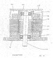
- the stator assembly 118 includes packetized Metal sheets 155 and windings 160 and delimits an interior in which the Rotor assembly 116 can be inserted.
- the rotor assembly 116 includes the motor shaft 110, an iron yoke 112 and permanent magnets 122.
- the bearings 126, 128 for the Bearings of the rotor arrangement can be integrated into a flange 124 of the motor housing 114 his.
- Fig. 11 serves to explain the basic structure of an electric motor
- the rotor body according to the invention has a substantially cylindrical rotor core, in which the permanent magnets are embedded.
- Rotors with embedded magnets are generally known in the prior art.
- a rotor configuration with a multi-pole spoke wheel-like design with radial extending embedded magnet is e.g. shown in "Design of Brushless PermanentMagnet Motors ", J.R. Hendershot Jr. and TJE Miller, Magna Physics Publishing and Clarendon Press, Oxford, 1994.
- the Rotor body in which the magnets are embedded serves as a conclusion.
- Rotors with embedded permanent magnets basically have the advantage that the Magnets can be fully encapsulated so that the rotor can handle even aggressive ones Media can come into contact without the magnetic material of a special one Surface protection to avoid e.g. Corrosion is required.
- rotor construction has the disadvantage that a leakage flux through the rotor core is nearby the wave is generated.
- EP 0803 962 A1 also shows that the slots for receiving the Permanent magnets have a bridge on their outer circumference to the Protect permanent magnets completely from the outside.
- WO 00/57537 describes a multi-pole permanent magnet rotor for one Electric motor with embedded magnets, which are arranged so that a River concentration results.
- the permanent magnets are designed as flat cubes spoke-like, are arranged radially to the rotor axis in recesses, which between Flow guide pieces are arranged, which are attached to the rotor body.
- For the assembly of the Magnets and the flux guide pieces become those as adjacent half pieces for one each Pole formed, and permanent magnets and flux guide pieces are connected to the sleeve Shaft attached.
- the U.S. Patent 4,327,302 describes a rotor structure with embedded Permanent magnets for use in an electric motor.
- the rotor body is off packetized, punched metal sheets assembled, which V-shaped openings have, with a permanent magnet in each of the two legs of each opening is embedded so that the permanent magnets are essentially spoke-shaped through the Extend rotor core.
- At the apex of the opening there are two neighboring ones Permanent magnets bridged by a free space that is air or a non-magnetic Material is filled.
- the purpose of the arrangement described is a simple one and compact structure for an electric motor with a large output power specify.
- EP 1 309 066 describes a rotor for an electric motor which is essentially like above with reference to U.S. Patent 4,327,302 is constructed.
- EP 1 309 066 wants through this structure with a simple construction of the laminated core over the leakage flux keep the wave as small as possible.
- Another design of a rotor with embedded Magnets are shown in EP 0 872 944 A1. The magnets are in a radial direction or arranged parallel to a radial direction of the rotor body. In EP 0 872 499 these are Permanent magnets arranged in a so-called double-spoke configuration.
- This "Double magnets" each include a pair of permanent magnets, the Magnetization direction is substantially the same. They can be parallel to each other be arranged as in the cited document, or at an angle to each other be inclined. This arrangement will improve the running behavior of the Electric motor and in particular a reduction in cogging torque and Torque ripple reached.
- the preferred application of the rotor body according to the invention is in a brushless one DC motor or another permanent magnet synchronous motor.
- Such engines can be used in a wide variety of applications, such as spindle motors for disk drives, motor-assisted systems in motor vehicles, e.g. Steering and Brake systems, power tools and many other applications.
- the radial arrangement of the permanent magnets embedded in the rotor core results the problem of stray flux in the area of the shaft on which the rotor sits.
- the wave is usually made of steel and acts as an additional inference for the magnetic flux through the rotor core. This creates considerable magnetic leakage losses. This Problem can be countered by not having a sleeve on the shaft or only weakly magnetically conductive material is applied, on which the Flußleitmaschine the Rotor core are attached, between which in turn the permanent magnets are embedded are. This design is relatively complex and requires additional items.
- the invention has for its object a rotor body for an electric motor to specify, which has embedded magnets, is easy to manufacture and yet the Problems of stray flux generation in the area of the motor shaft described above avoids.
- the rotor body according to the invention has an essentially cylindrical rotor core a central opening. Permanent magnets are embedded in the rotor core and extend essentially spoke-shaped through the rotor core. According to the invention selected adjacent permanent magnets at their radially inner ends at least one auxiliary magnet magnetically coupled. As described, the Prior art rotor cores have the problem that in the area of the shaft on the radial inner ends of the permanent magnets generate a partially considerable leakage flux becomes. The invention is based on the consideration of the magnetic flux lines where the The risk of undesirable stray fields forming is great, to redirect and into the desired one Direction, i.e. to steer radially outwards to the stator.
- the auxiliary magnets will be preferably magnetized and arranged such that the magnetic field lines in Concentrate the space between the adjacent permanent magnets, causing again the magnetic flux between the rotor and the stator and thus the effectiveness of the Electric motor increased. Scattering losses can be significantly reduced as a result.
- the magnetic field lines are intensified in the outer area of the Rotor body directed, which increases the effectiveness of the electric motor.
- the structure of the rotor body can be one or more auxiliary magnets for coupling a pair of adjacent permanent magnets can be provided.
- the radially inner ones Ends of adjacent permanent magnets are bridged by a recess in the rotor core, the auxiliary magnet for magnetic coupling of these permanent magnets in the Recess is arranged.
- the recess is basically with air or another poorly magnetically conductive material filled, the auxiliary magnets the recess can fill partially or completely and to an appropriate extent the air or that replace magnetically poorly conductive material.
- the effect of the auxiliary magnets is that the Magnetic field lines in the space between the adjacent permanent magnets be concentrated.
- an auxiliary magnet can be the radially inner one Also completely bridge the ends of two adjacent permanent magnets.
- the auxiliary magnet and the associated neighboring ones are of a special design Permanent magnets formed in one piece. For this purpose, preferably V-shaped ones Magnets used. This results in a particularly simple structure.
- the recess can be by a circumferential web at the central opening of the Rotor core, the radially inner ends of the associated neighboring ones Permanent magnets and radial side webs must be limited so that they to the center of the Rotor core is closed or open. This is achieved in that the rotating Web is either continuous or with interruptions.
- the execution with continuous inner web has the advantage that the rotor body on the inner ring, where it on the Shaft is applied stably and the permanent magnets are fully embedded and are protected.
- the adjacent permanent magnets are through bridges a recess in the rotor core as described above, the or the Auxiliary magnets, however, are not arranged in the recess, but in the circumferential one inner web are integrated in the central opening of the rotor core.
- the circumferential web interruptions in which the auxiliary magnets are inserted can. This forms an overall closed inner ring of the rotor body.
- Permanent magnets can be combined into pairs and one pair each Adjacent permanent magnets magnetically by one (or more) auxiliary magnets is coupled.
- the permanent magnets of a pair can be in the same direction or in opposite directions be magnetized.
- the permanent magnets are of the type Double spokes in pairs of magnetized permanent magnets in the rotor core arranged, with adjacent pairs at the radially inner ends of two Adjacent permanent magnets are magnetically coupled by an auxiliary magnet.
- auxiliary magnet or magnets are preferably magnetized in the radial direction in order to Magnetic field lines in the space between the selected neighboring ones Focus permanent magnets. Adjacent auxiliary magnets can be selected here be magnetized in the same or opposite direction.
- the permanent magnets at least at their radially inner ends or at their radially outer ends are enclosed by the rotor core, around a one-piece, coherent rotor core to build. If the inner ring of the flux guide pieces is interrupted towards the shaft, this results nevertheless contiguous flux guide pieces, provided that the permanent magnets on the Are enclosed on the outside of the rotor body.
- the Rotor body has recesses or cutouts for the permanent magnets, which are open radially outwards, i.e. the permanent magnets are on the outside of the Rotor body is not completely covered by the flux guide pieces. Then the river guides no longer connected in one piece.
- this version has the advantage that the Magnetic flux is concentrated even more on the outside of the rotor, causing the Effectiveness and maximum power of the engine is further increased.
- the permanent magnets are radial on them outer ends completely enclosed by the rotor core. This gives you a rotor body with completely embedded rotor magnets, so that the rotor without Problems can also come into contact with aggressive media. It can be a bigger one A variety of magnetic materials are used, and especially such Materials that require additional surface protection for exposed magnets would.
- the rotor core consists of a ferromagnetic material, preferably of Punching plates, which are packaged to avoid eddy currents. Alternatively, you can Ferrite materials are used.
- the rotor core can be constructed so that it has slots has, into which the permanent magnets are inserted laterally. Then will the rotor core is closed laterally so that the magnets are hermetically sealed and therefore do not need to be surface coated.
- magnetic materials for example neodymium-iron-boron (NbFeB) or samarium-cobalt (SmCo) magnets used. To prevent corrosion of these materials, they usually have to be coated. This is not necessary due to the complete embedding in the rotor core. Furthermore, by completely embedding the permanent magnets in the rotor core additional mechanical protection of the permanent magnets achieved.
- the invention is also applicable to an external rotor motor.
- this constellation the recesses, which bridge two adjacent permanent magnets, in the Provided near the outer periphery of the rotor core.
- Fig. 1 shows a schematic sectional view through a rotor body based on the magnetic circuit is ideally constructed.
- the rotor body 10 is on a shaft 12, the usually consists of steel, applied.
- a sleeve 14 is on the Shaft 12 glued or pressed, and flux guide pieces 16 are attached to the sleeve 14, between which permanent magnets 18 are embedded.
- the sleeve 14 has the function prevent magnetic leakage flux between the flux guide pieces 16 and the shaft 12.
- it is made of a non-magnetic or poorly magnetically conductive material manufactured. With the aid of the sleeve 14 it can thus be achieved that in the region of the shaft 12 practically no magnetic losses occur.
- This structure of the Rotor body 10 is thus ideally related to the magnetic circuit. However, he does Disadvantage that he needs many items, which complicates the mechanical structure and becomes complex.
- Fig. 2a shows a schematic sectional view through a rotor body, the one Starting point for the invention.
- the rotor body 20 comprises flux guide pieces 22, which via outer and inner webs 24, 26 on the outer circumference or at a central Opening 28 of the rotor body 20 are related.
- the inner webs 26 form the embodiment shown a closed ring and thereby delimit the central one Opening 28 a.
- Permanent magnets 30 are embedded between the flux guide pieces 22, which extend in a radial shape through the rotor body 20.
- the outer webs 24 have the function of the permanent magnets 30 towards the outside fully embed in the rotor body 20 and protect so that the permanent magnets 30 cannot come into contact with the surrounding medium of the rotor body 20.
- a The inner webs 26 have a similar function. The inner webs 26 ensure a torsion-proof connection of the rotor body 20 with the shaft 12. The webs 24, 26 connect the flux guide pieces 22 so that the rotor body 20 is in one piece forms a coherent body.
- the inner webs 26 form one closed ring, so that the rotor body 20 directly, without the interposition of a sleeve, applied to the shaft (not shown) e.g. can be pressed on or glued on.
- the inner webs 26 are connected to the flux guide pieces 22 via short radial webs 42 connected and each delimit a recess 32.
- the one shown in Figure 2 Execution bridges each recess 32 two adjacent permanent magnets 30, whereby in this embodiment, the inner webs 26 each have the same name Connect permanent magnets 30.
- the inner webs 26 In the embodiment shown in Fig. 2 connect the Bridges 26 the S pole.
- the inner webs could only be used connect the N poles. This results in a design of the rotor body 20 in which the Bridges 26 each bridge the radially inner ends of two permanent magnets 30 and thereby delimit the recess 32, which is not or only with air or another weakly magnetically conductive medium can be filled.
- the flux guide pieces 22 are made of ferromagnetic material and are preferably made of Punching plates are manufactured, which are packaged to avoid eddy currents. alternative they can be made of ferrite material.
- the flux guide pieces 22 of the rotor body 20 can be manufactured as a coherent component in which the magnets 30 be inserted laterally. Then the rotor body 20 is closed, so that the Magnets are hermetically sealed and do not need to be surface coated.
- the rotor body 20 is surrounded by a stator 34, which has a stator body 36 and Stator windings 38 includes.
- the stator body 36 can in turn consist of stamped sheets, which are packaged as is well known in the art.
- All permanent magnetic materials can be used as magnetic materials become. Examples are neodymium iron boron (NbFeB) and samarium cobalt (SmCo), and also plastic-bonded magnetic materials.
- Fig. 2b shows a schematic sectional view through the rotor body of Fig. 2a .. Zur Explanation of the effect of the cutouts 32 are shown in FIG. 2b flow guidelines 40.
- the same components as in Fig. 2a are denoted by the same reference numerals and not described again in detail.
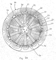
- FIG 3a shows a schematic sectional view through a further embodiment of the Rotor body, which is the basis for the invention.
- the rotor body 44 includes flux guide pieces 46, which have outer and inner webs 48 and 50 on the outer circumference or at one central opening 52 of the rotor body 44 are connected to form a coherent Form body.
- the inner webs 50 form one in the embodiment shown closed ring and delimit the central opening 52.
- the Permanent magnets 54, 54 'of a pair each have substantially the same Direction of magnetization, i.e. Arrangement of north and south poles, which is indicated by the arrows in Figure 4 is indicated. This forms one between the permanent magnets 54, 54 ' Do not pair poles, but the magnetic field lines connect the inner sides of the Permanent magnets of a pair on the shortest route, as can be seen from Figure 3b.
- the Permanent magnets 54, 54 'of a pair essentially act as one Double magnet, making the field generated by the magnets compared to the execution of the Figure 2a can be reinforced.
- the arrangement of the permanent magnets at an angle serves to improve the torque and in particular to suppress Cogging torque.
- the function of the webs 48, 50 for protecting the embedded permanent magnets 54, 54 'and for direct mounting of the rotor body 44 on a shaft is essentially as with reference described in Figure 2. Furthermore, the webs 50 border in connection with short radial ones Web 56 recesses 58, each of which adjacent permanent magnets 54, 54 ' bridge adjacent permanent magnet pairs. Connect the inner webs 50 in the embodiment shown, the gaps between the permanent magnets 54, 54 'of a pair of permanent magnets. The effect of the recesses 58 formed thereby is as described with reference to Figures 2a and 2b and as in the following still in relation explained in Figure 3b.
- the flux guide 46 consist of ferromagnetic Material and are preferably made from stamped sheets which are packaged to Avoid eddy currents.
- the flux guide pieces 46 of the rotor body 44 are preferably as produced a coherent component.
- the rotor body 44 shown in FIG. 3a is from a stator 60 to form a Working air gap 62 surrounded between the stator 60 and the rotor body 44.
- the stator 60 comprises a stator body 64 with associated stator poles on which phase windings 66, 66 'are applied.
- the stator body 64 can in turn be made from stamped sheets be packaged, as is generally known in the prior art.
- FIG. 3b shows a similar schematic sectional illustration through the rotor body 44 of FIG Fig. 3a, corresponding components with the same reference numerals as in Figure 3a are designated. To explain the effect of the recesses 58 are in Figure 3b River lines drawn.
- FIG. 3c A modification of the embodiment in FIG. 3a is shown in FIG. 3c, the area of FIG outer webs 48 notches 68 provided on the outer circumference of the rotor body 44, the are evenly or unevenly distributed over the circumference of the rotor body 44.
- This Notches 68 improve and reduce the torque of the electric motor during operation in particular the cogging torque again compared to the previously discussed explanations.
- the rotor body can be manufactured in that Slits 70 for receiving the permanent magnets 54, 54 'in the rotor body 44 are formed the permanent magnets are inserted into these slots 70 and the Rotor body 44 is then closed.
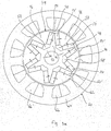
- FIG. 4a Another embodiment of a rotor body, which is a starting point for the invention, is shown schematically in Figure 4a. This version corresponds essentially to that with Referring to Figure 2a embodiment described, the radially inner webs but do not form a closed ring. Corresponding components are as in Figure 2a marked with the same reference numerals.
- the recesses 32 are the short radial Web 42 and delimited by web stub 72, which at the central inner opening 28th of the rotor body 20 adjoin.
- the radially inner webs or web stubs 72 are not connected to one another through the cutouts 32 the same suppression of stray fluxes between the rotor body 20 and shaft reached, as described above with respect to the previous statements.
- 4b shows the course of the magnetic flux in this embodiment.
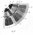
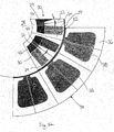
- 5a shows schematically shows a sectional view through a part of a rotor body according to the Invention, the embodiment of Fig. 5a on the design shown in Fig. 2a Rotor body is based. Corresponding components have the same reference symbols referred to and not described again in detail.
- an auxiliary magnet 74 is in the recess 32 inserted, which is arranged centrally between two adjacent permanent magnets 30.
- the Magnetization direction of the permanent magnet 30 and the auxiliary magnet 74 are through Arrows (N ⁇ S) indicated.
- the geometric arrangement of the permanent magnets 30 and their magnetization corresponds to the embodiment of FIG. 2b. Becomes a professional recognize that the inventive design of the rotor body in various Constellations of rotors with embedded permanent magnets can be used.
- each auxiliary magnet 74 fills only one Part of a recess 32.
- the auxiliary magnets 74 have the function of the stray flux on the to further reduce the radially inner side of the permanent magnets 30.
- FIG. 5b which corresponds to the illustration in FIG. 5a, the magnetic flux lines generated during operation are shown.
- the auxiliary magnets 74 concentrate the magnetic flux lines in the space between two adjacent permanent magnets 30 and steer them into the desired one Direction, i.e., outwards to the stator 34.
- the rotor body 20th has contiguous flux guide pieces and can thus be formed in one piece.
- the Auxiliary magnet 74 can be inserted laterally into the recess 32 in the rotor body 20 and therein by gluing, pouring out the remaining recess 32, bracing or on others Be fixed way.
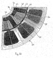
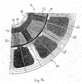
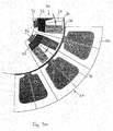
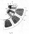
- FIGS. 6a and 7a show similar designs as Fig. 5a, wherein in Figs. 6a and 7a Auxiliary magnets 76 and 78 fill an increasingly larger portion of the recess 32. In the 7a, the auxiliary magnet 78 completely fills the recess.
- the others Components of the rotor bodies shown in FIGS. 6a and 7a correspond to the illustration 5a and are identified by the same reference numerals.
- 6b and 7b show corresponding representations of the rotor body according to the invention, in which the magnetic flux lines, which result from the operation of the electric motor, are supplemented are.
- auxiliary magnets can experience numerous modifications. Can also be different trained auxiliary magnets in all versions of a rotor body, with reference 2 to 4 have been described, as well as with other types of rotor bodies embedded permanent magnets can be used. The auxiliary magnets can also be used one or more composite magnets.
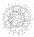
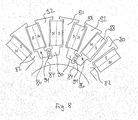
- the rotor body 8 shows a further embodiment of the rotor body according to the invention in one schematic representation of a part of the rotor body.
- the rotor body includes Flußleitmaschine 80, which via radial webs 82 and inner webs 84 at a central Opening of the rotor body.
- the inner webs 84 form one closed ring and thereby limit the central opening of the rotor body.
- Punchings 86 are provided between the flow guide pieces 80, the space for Provide two adjacent permanent magnets 88 and offer one Recess 90 between the radially inner ends of these adjacent Form permanent magnets 88.
- the recess 90 for Inclusion of the permanent magnets 88 is open radially to the outside; i.e., the permanent magnets 88 are not completely encompassed by the flow directors 80, 92. That’s why Flußleitmaschine of the rotor body no longer connected in one piece.
- the individual flux guide pieces 80, 92 have lugs on their outer circumference Holder of the permanent magnets 88.
- encapsulation or potting of the rotor body can also be used for all of them other versions are provided.
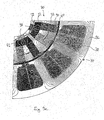
- FIGS. 9a and 9b show further embodiments of the rotor body according to the invention, which in the are essentially based on the variant of the rotor body shown in FIG. 4a.
- the auxiliary magnets 96, 98 are not within the Recess 32 but integrated into the rotor body in the area of the inner webs 72.
- the other components of the embodiments shown in FIGS. 9a and 9b are as with 4a and are identified by the same reference numerals. On reference is made to the above description.
- Those in the area of the inner webs 72 arranged auxiliary magnets 96, 98 can be magnetized with the same or opposite poles, such as is indicated by the arrows in FIGS. 9a and 9b. They can also consist of one or be composed of several individual magnets.
- the course of the magnetic flux lines for the 9b is shown in FIG. 9c.
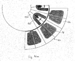
- FIG. 10a Another embodiment of the rotor body according to the invention is shown schematically in Fig. 10a shown.
- the auxiliary magnet is two at a time adjacent permanent magnets 100 formed in one piece.
- the rotor body 102 has preferably suitable V-shaped or V-shaped punched holes in which the magnet 100 can be inserted.
- the direction of magnetization of the two legs and the The apex region of the magnet is indicated by arrows in FIG. 10a.
- FIG. 10b shows the course of the magnetic flux lines in the operation of the embodiment of FIG Fig. 10a. It can be seen that there is no magnetic in the area of the inner ring of the rotor body Leakage flux occurs.
- a motor with half the number of poles in relation to the motors described above can are generated in that two adjacent, successive Permanent magnets have the same direction of magnetization, or in that every second Permanent magnet is omitted and the corresponding space for receiving this Permanent magnet remains empty.
Landscapes
- Engineering & Computer Science (AREA)
- Power Engineering (AREA)
- Permanent Field Magnets Of Synchronous Machinery (AREA)
- Iron Core Of Rotating Electric Machines (AREA)
Applications Claiming Priority (4)
| Application Number | Priority Date | Filing Date | Title |
|---|---|---|---|
| DE10318624 | 2003-04-24 | ||
| DE10318624A DE10318624A1 (de) | 2003-04-24 | 2003-04-24 | Rotorkörper für einen Elektromotor |
| DE2003145417 DE10345417A1 (de) | 2003-09-30 | 2003-09-30 | Rotorköper für einen Elektromotor |
| DE10345417 | 2003-09-30 |
Publications (2)
| Publication Number | Publication Date |
|---|---|
| EP1471621A2 true EP1471621A2 (fr) | 2004-10-27 |
| EP1471621A3 EP1471621A3 (fr) | 2005-12-14 |
Family
ID=32963536
Family Applications (1)
| Application Number | Title | Priority Date | Filing Date |
|---|---|---|---|
| EP04006412A Withdrawn EP1471621A3 (fr) | 2003-04-24 | 2004-03-17 | Elément de rotor pour un moteur électrique |
Country Status (2)
| Country | Link |
|---|---|
| US (1) | US7196446B2 (fr) |
| EP (1) | EP1471621A3 (fr) |
Cited By (5)
| Publication number | Priority date | Publication date | Assignee | Title |
|---|---|---|---|---|
| RU2316103C2 (ru) * | 2005-07-14 | 2008-01-27 | "Центр Разработки Нефтедобывающего Оборудования" ("Црно") | Магнитная система ротора |
| DE102007059203A1 (de) * | 2007-12-08 | 2009-06-18 | Weh, Herbert, Prof. Dr.-Ing. Dr. h.c. | Permanentmagneterregte Synchronmaschine mit hoher Kraftdichte bei kleiner Magnetstreuung |
| EP2133981A2 (fr) * | 2008-06-12 | 2009-12-16 | General Electric Company | Machine électrique à haute densité de couple |
| US9080279B2 (en) | 2011-10-24 | 2015-07-14 | Lg Electronics Inc. | Washing machine to produce three-dimensional motion |
| CN106165262A (zh) * | 2014-04-10 | 2016-11-23 | 利莱森玛电机公司 | 用于旋转电机的转子 |
Families Citing this family (66)
| Publication number | Priority date | Publication date | Assignee | Title |
|---|---|---|---|---|
| EP1624554A1 (fr) * | 2004-08-02 | 2006-02-08 | Nissan Motor Co., Ltd. | Machine électrique tournante |
| CN100435453C (zh) * | 2004-09-15 | 2008-11-19 | 日产自动车株式会社 | 旋转电机 |
| ITBZ20050063A1 (it) * | 2005-11-29 | 2007-05-30 | High Technology Invest Bv | Pacco di lamierini per generatori e motori elettrici e procedimento per la sua attuazione |
| ITBZ20050062A1 (it) * | 2005-11-29 | 2007-05-30 | High Technology Invest Bv | Rotore a magneti permanenti per generatori e motori elettrici |
| DK1934474T3 (da) * | 2005-09-21 | 2010-06-21 | Wilic S A R L | Lejepakningsanordning med labyrintpaknings- og skruepakningskombination |
| JP4489002B2 (ja) * | 2005-10-26 | 2010-06-23 | 三菱電機株式会社 | ハイブリッド励磁回転電機、及びハイブリッド励磁回転電機を備えた車両 |
| US7385328B2 (en) * | 2006-05-23 | 2008-06-10 | Reliance Electric Technologies, Llc | Cogging reduction in permanent magnet machines |
| SE530697C2 (sv) * | 2006-12-19 | 2008-08-19 | Bae Systems Haegglunds Ab | Rotor till en elmotor, rotorplåtar för uppbyggnad av rotorn, samt en elmotor med en sådan rotor |
| US7598645B2 (en) * | 2007-05-09 | 2009-10-06 | Uqm Technologies, Inc. | Stress distributing permanent magnet rotor geometry for electric machines |
| JP4466681B2 (ja) * | 2007-05-11 | 2010-05-26 | トヨタ自動車株式会社 | 回転電機のロータおよび回転電機 |
| US8049376B2 (en) * | 2008-01-29 | 2011-11-01 | Ford Global Technologies, Llc | Motor system with magnet for a vehicle fuel pump |
| CN101978578A (zh) * | 2008-03-19 | 2011-02-16 | 霍加纳斯股份有限公司 | 集成的转子磁极件 |
| ITMI20081122A1 (it) * | 2008-06-19 | 2009-12-20 | Rolic Invest Sarl | Generatore eolico provvisto di un impianto di raffreddamento |
| IT1390758B1 (it) | 2008-07-23 | 2011-09-23 | Rolic Invest Sarl | Generatore eolico |
| RU2375807C1 (ru) * | 2008-11-10 | 2009-12-10 | Государственное образовательное учреждение высшего профессионального образования "Санкт-Петербургский государственный морской технический университет" | Вентильный электродвигатель с постоянными магнитами |
| IT1391939B1 (it) * | 2008-11-12 | 2012-02-02 | Rolic Invest Sarl | Generatore eolico |
| IT1391770B1 (it) | 2008-11-13 | 2012-01-27 | Rolic Invest Sarl | Generatore eolico per la generazione di energia elettrica |
| JP5305887B2 (ja) | 2008-12-18 | 2013-10-02 | 株式会社東芝 | 永久磁石式回転電機 |
| IT1392804B1 (it) * | 2009-01-30 | 2012-03-23 | Rolic Invest Sarl | Imballo e metodo di imballo per pale di generatori eolici |
| US8222787B2 (en) * | 2009-04-01 | 2012-07-17 | General Electric Company | Electric machine |
| IT1393937B1 (it) * | 2009-04-09 | 2012-05-17 | Rolic Invest Sarl | Aerogeneratore |
| IT1393707B1 (it) | 2009-04-29 | 2012-05-08 | Rolic Invest Sarl | Impianto eolico per la generazione di energia elettrica |
| IT1394723B1 (it) | 2009-06-10 | 2012-07-13 | Rolic Invest Sarl | Impianto eolico per la generazione di energia elettrica e relativo metodo di controllo |
| IT1395148B1 (it) | 2009-08-07 | 2012-09-05 | Rolic Invest Sarl | Metodo e apparecchiatura di attivazione di una macchina elettrica e macchina elettrica |
| IT1397081B1 (it) | 2009-11-23 | 2012-12-28 | Rolic Invest Sarl | Impianto eolico per la generazione di energia elettrica |
| IT1398060B1 (it) | 2010-02-04 | 2013-02-07 | Wilic Sarl | Impianto e metodo di raffreddamento di un generatore elettrico di un aerogeneratore, e aerogeneratore comprendente tale impianto di raffreddamento |
| IT1399201B1 (it) | 2010-03-30 | 2013-04-11 | Wilic Sarl | Aerogeneratore e metodo di rimozione di un cuscinetto da un aerogeneratore |
| IT1399511B1 (it) | 2010-04-22 | 2013-04-19 | Wilic Sarl | Generatore elettrico per un aerogeneratore e aerogeneratore equipaggiato con tale generatore elettrico |
| ITMI20110377A1 (it) | 2011-03-10 | 2012-09-11 | Wilic Sarl | Macchina elettrica rotante per aerogeneratore |
| ITMI20110378A1 (it) | 2011-03-10 | 2012-09-11 | Wilic Sarl | Macchina elettrica rotante per aerogeneratore |
| ITMI20110375A1 (it) | 2011-03-10 | 2012-09-11 | Wilic Sarl | Turbina eolica |
| KR101243491B1 (ko) * | 2011-04-13 | 2013-03-13 | 뉴모텍(주) | 모터의 로터 |
| JP5835928B2 (ja) | 2011-04-15 | 2015-12-24 | 三菱重工業株式会社 | 電動モータおよびそれを用いた電動圧縮機 |
| KR101786922B1 (ko) * | 2011-05-26 | 2017-10-18 | 삼성전자주식회사 | 로터 및 구동 모터 |
| CN102801273A (zh) * | 2011-05-26 | 2012-11-28 | 福斯特资产有限公司 | 无刷电机及其系统 |
| PL2732535T3 (pl) * | 2011-07-14 | 2019-06-28 | Jean I. TCHERVENKOV | Zespół kołowy określający silnik elektryczny/generator |
| KR101886155B1 (ko) * | 2011-10-10 | 2018-08-08 | 삼성전자 주식회사 | 모터 및 모터용 로터 |
| KR101940755B1 (ko) * | 2012-01-16 | 2019-01-21 | 삼성전자 주식회사 | 회전자 및 이를 포함하는 전동기 |
| US20130249342A1 (en) * | 2012-03-20 | 2013-09-26 | Kollmorgen Corporation | Cantilevered Rotor Magnet Support |
| KR20140023126A (ko) * | 2012-08-17 | 2014-02-26 | 삼성전기주식회사 | 영구자석 매립형 동기모터용 회전자 및 이를 포함하는 영구자석 매립형 동기모터 |
| JP5713075B2 (ja) * | 2012-09-28 | 2015-05-07 | ダイキン工業株式会社 | ロータおよび回転電気機械 |
| EP2926438A2 (fr) | 2012-11-30 | 2015-10-07 | Arçelik Anonim Sirketi | Rotor à aimant permanent à ailettes |
| US10199892B2 (en) | 2012-11-30 | 2019-02-05 | Arcelik Anonim Sirketi | Spoke permanent magnet rotor |
| WO2014082840A2 (fr) | 2012-11-30 | 2014-06-05 | Arcelik Anonim Sirketi | Rotor à aimant permanent à ailettes |
| CN104682650A (zh) * | 2013-11-28 | 2015-06-03 | 德昌电机(深圳)有限公司 | 电机转子以及具有该电机转子的无刷电机 |
| WO2016002994A1 (fr) * | 2014-07-04 | 2016-01-07 | 삼성전자주식회사 | Moteur |
| US10326323B2 (en) | 2015-12-11 | 2019-06-18 | Whirlpool Corporation | Multi-component rotor for an electric motor of an appliance |
| DE102016207800A1 (de) * | 2016-05-04 | 2017-11-09 | Volkswagen Aktiengesellschaft | Rotor für einen Elektromotor |
| DE102016209174B4 (de) * | 2016-05-25 | 2024-10-24 | Vitesco Technologies GmbH | Rotor |
| US10516307B2 (en) * | 2016-08-30 | 2019-12-24 | Hamilton Sundstrand Corporation | Interior permanent magnet motor/rotor with curved and spoke-type permanent magnets |
| US10704180B2 (en) | 2016-09-22 | 2020-07-07 | Whirlpool Corporation | Reinforcing cap for a tub rear wall of an appliance |
| JP6638615B2 (ja) * | 2016-09-29 | 2020-01-29 | 株式会社デンソー | 同期回転電機 |
| FR3064837B1 (fr) * | 2017-04-03 | 2020-01-17 | Moving Magnet Technologies | Rotor pour machine electrique a aimants permanents internes |
| US10693336B2 (en) | 2017-06-02 | 2020-06-23 | Whirlpool Corporation | Winding configuration electric motor |
| TWM576750U (zh) | 2017-07-25 | 2019-04-11 | 美商米沃奇電子工具公司 | 電氣組合物、電動化裝置系統、電池組、電馬達、馬達總成及電馬達總成 |
| CN113169604B (zh) * | 2018-11-26 | 2025-03-21 | 美蓓亚三美株式会社 | 转子及使用该转子的电机、以及电子设备 |
| US11780061B2 (en) | 2019-02-18 | 2023-10-10 | Milwaukee Electric Tool Corporation | Impact tool |
| US11245317B2 (en) | 2019-12-05 | 2022-02-08 | Whirlpool Corporation | Direct drive electric motor having stator and magnet configurations for improved torque capability |
| CN113839490B (zh) * | 2020-06-24 | 2023-05-30 | 莱克电气股份有限公司 | 一种高效低噪音的电机及其应用 |
| SE545089C2 (en) * | 2020-08-11 | 2023-03-28 | Scania Cv Ab | Rotor and electrical machine |
| WO2022098636A1 (fr) | 2020-11-03 | 2022-05-12 | H3X Technologies Inc. | Moteur électrique à onduleur intégré et système de refroidissement partagé |
| WO2022148994A1 (fr) * | 2021-01-08 | 2022-07-14 | Polywavepower Ip Proprietary Limited | Machine électrique à induction bipolaire |
| CN112953056B (zh) * | 2021-01-25 | 2022-09-13 | 格力电器(武汉)有限公司 | 转子组件及具有其的电机 |
| JP7630311B2 (ja) * | 2021-03-12 | 2025-02-17 | 本田技研工業株式会社 | ロータおよび回転電機 |
| CN114039435B (zh) * | 2021-11-04 | 2023-10-03 | 广东美芝精密制造有限公司 | 转子结构、电机结构、压缩机结构和制冷设备 |
| JP2023077856A (ja) * | 2021-11-25 | 2023-06-06 | ミネベアミツミ株式会社 | モータ |
Family Cites Families (33)
| Publication number | Priority date | Publication date | Assignee | Title |
|---|---|---|---|---|
| DE222745C (fr) | ||||
| BE694098A (fr) * | 1966-03-03 | 1967-07-17 | ||
| DE2062486A1 (de) * | 1970-12-18 | 1972-07-06 | Siemens Ag | Permanenterregte elektrische Maschine |
| DE2608421C3 (de) * | 1976-03-01 | 1979-01-18 | Siemens Ag, 1000 Berlin Und 8000 Muenchen | Dauermagneterregter Innenläufer für eine Synchronmaschine |
| JPS54148214A (en) * | 1978-05-13 | 1979-11-20 | Hitachi Ltd | Permanent-magnet-type synchronous motor |
| US4339874A (en) * | 1978-12-26 | 1982-07-20 | The Garrett Corporation | Method of making a wedge-shaped permanent magnet rotor assembly |
| US4327302A (en) | 1979-09-21 | 1982-04-27 | General Electric Company | Electronically commutated motor, stationary and rotatable assemblies therefore, and lamination |
| JPS63140644A (ja) * | 1986-12-03 | 1988-06-13 | Fuji Electric Co Ltd | 回転電機の永久磁石付き回転子 |
| IT1219228B (it) * | 1988-04-21 | 1990-05-03 | Antonino Fratta | Macchina elettrica sincrona a riluttanza dotata di mezzi di rifasamento intrinseco |
| US4922152A (en) * | 1988-07-27 | 1990-05-01 | Siemens Energy & Automation, Inc. | Synchronous machine rotor lamination |
| JP3224890B2 (ja) | 1993-02-15 | 2001-11-05 | ファナック株式会社 | 同期電動機のロータ |
| DE4423620A1 (de) | 1994-07-06 | 1996-01-11 | Philips Patentverwaltung | Mittels Permanentmagneten erregbarer elektrischer Motor, insbesondere Innenläufer- oder Außenläufermotor |
| JPH08275419A (ja) * | 1995-03-30 | 1996-10-18 | Meidensha Corp | 永久磁石式回転機の回転子 |
| JP3397019B2 (ja) | 1995-04-21 | 2003-04-14 | 三菱電機株式会社 | 永久磁石形モータ |
| IT240620Y1 (it) | 1996-04-23 | 2001-04-02 | Bamo Elettroutensili S R L | Struttura di pacco polare, per rotori a magneti permanenti dialternatori e simili |
| TW364234B (en) * | 1997-04-14 | 1999-07-11 | Sanyo Electric Co | Rotor for an electric motor |
| KR100252393B1 (ko) * | 1997-05-13 | 2000-04-15 | 윤종용 | 영구자석매립형회전자구조 |
| JP3818340B2 (ja) | 1997-09-26 | 2006-09-06 | 株式会社富士通ゼネラル | 永久磁石電動機 |
| KR100263445B1 (ko) | 1997-11-13 | 2000-08-01 | 윤종용 | 브러시리스 dc모터용 회전자 |
| US6800977B1 (en) * | 1997-12-23 | 2004-10-05 | Ford Global Technologies, Llc. | Field control in permanent magnet machine |
| FI980980A7 (fi) | 1998-05-04 | 1999-11-05 | Abb Motors Oy | Kestomagneettitahtikone |
| DE19914021C2 (de) | 1999-03-19 | 2002-01-31 | Siemens Ag | Mehrpoliger, permanenterregter Rotor für eine rotierende elektrische Maschine und Verfahren zur Herstellung eines solchen Läufers |
| FR2802726B1 (fr) * | 1999-12-15 | 2007-10-05 | Leroy Somer | Rotor a aimants permanents a concentration de flux |
| JP2001314052A (ja) * | 2000-02-25 | 2001-11-09 | Nissan Motor Co Ltd | 同期電動機のロータ構造 |
| JP2001339885A (ja) * | 2000-05-24 | 2001-12-07 | Aichi Emerson Electric Co Ltd | 電動機の永久磁石回転子 |
| JP3513467B2 (ja) | 2000-06-16 | 2004-03-31 | ファナック株式会社 | 同期電動機のロータ |
| DE10100718A1 (de) | 2001-01-10 | 2002-07-18 | Miele & Cie | Permanentmagnet-Rotor für eine elektrische Maschine |
| EP1223658A1 (fr) | 2001-01-12 | 2002-07-17 | Siemens Aktiengesellschaft | Rotor à aimant permanent avec pertes de flux réduites |
| JP2003032926A (ja) * | 2001-07-10 | 2003-01-31 | Teijin Seiki Co Ltd | 永久磁石型モータ |
| JP2003088019A (ja) * | 2001-09-10 | 2003-03-20 | Fujitsu General Ltd | 永久磁石電動機 |
| JP3835231B2 (ja) | 2001-10-04 | 2006-10-18 | 松下電器産業株式会社 | 電動機 |
| DE10153750A1 (de) | 2001-10-31 | 2003-05-22 | Siemens Ag | Rotor für PM-Synchronmaschine |
| JP2003264947A (ja) | 2002-03-08 | 2003-09-19 | Fujitsu General Ltd | 永久磁石電動機 |
-
2004
- 2004-03-17 EP EP04006412A patent/EP1471621A3/fr not_active Withdrawn
- 2004-04-23 US US10/830,474 patent/US7196446B2/en not_active Expired - Fee Related
Cited By (5)
| Publication number | Priority date | Publication date | Assignee | Title |
|---|---|---|---|---|
| RU2316103C2 (ru) * | 2005-07-14 | 2008-01-27 | "Центр Разработки Нефтедобывающего Оборудования" ("Црно") | Магнитная система ротора |
| DE102007059203A1 (de) * | 2007-12-08 | 2009-06-18 | Weh, Herbert, Prof. Dr.-Ing. Dr. h.c. | Permanentmagneterregte Synchronmaschine mit hoher Kraftdichte bei kleiner Magnetstreuung |
| EP2133981A2 (fr) * | 2008-06-12 | 2009-12-16 | General Electric Company | Machine électrique à haute densité de couple |
| US9080279B2 (en) | 2011-10-24 | 2015-07-14 | Lg Electronics Inc. | Washing machine to produce three-dimensional motion |
| CN106165262A (zh) * | 2014-04-10 | 2016-11-23 | 利莱森玛电机公司 | 用于旋转电机的转子 |
Also Published As
| Publication number | Publication date |
|---|---|
| US7196446B2 (en) | 2007-03-27 |
| EP1471621A3 (fr) | 2005-12-14 |
| US20050001503A1 (en) | 2005-01-06 |
Similar Documents
| Publication | Publication Date | Title |
|---|---|---|
| DE60212406T2 (de) | Läufer mit eingebetteten Dauermagneten | |
| DE10318624A1 (de) | Rotorkörper für einen Elektromotor | |
| DE112016006772T5 (de) | Elektromotor und Klimaanlage | |
| WO2013135257A2 (fr) | Machine électrique | |
| DE10309776A1 (de) | Innenläufermotor | |
| DE102013226379A1 (de) | Elektrische Maschine mit jeweils zumindest zwei Klemmnasen zur Befestigung eines Dauermagneten | |
| DE102010023813A1 (de) | Elektrokleinmotor | |
| DE102013009115A1 (de) | Rotor für eine permanenterregte elektrische Maschine sowie dessen Verwendung | |
| DE112010003859T5 (de) | Drehmotor vom Lundell-Typ | |
| DE102014101221A1 (de) | Rotor für einen Permanentmagnet-Motor, Verfahren zur Herstellung eines Rotors für einen Permanentmagnet-Motor sowie Permanentmagnet-Motor | |
| DE10229333A1 (de) | Elektrische Maschine, insbesondere bürstenlose Maschine mit permanentmagnetisch erregtem Läufer | |
| DE102004017507A1 (de) | Rotoranordnung für eine elektrische Maschine | |
| DE102005047771A1 (de) | Rotoranordnung für eine elektrische Maschine und Verfahren zum Herstellen der Rotoranordnung | |
| DE102015004669A1 (de) | Motor | |
| DE102006036707B3 (de) | Trägheitsarmer Direktantrieb | |
| DE102014115563A1 (de) | Rotor und Motor | |
| DE102016212022A1 (de) | Rotor | |
| DE102009003228A1 (de) | Elektrische Maschine | |
| EP1711994B1 (fr) | Unite modulaire stator | |
| EP3157140B1 (fr) | Rotor a couple optimise et petit moteur electrique dote d'un tel rotor | |
| DE102015117081A1 (de) | Rotorkörper für einen Elektromotor und Synchron-Reluktanzmotor | |
| DE102020126339A1 (de) | Magnetische Einheit einer rotierenden elektrischen Maschine | |
| DE102007032135A1 (de) | Elektrische Maschine | |
| DE102012218993A1 (de) | Läuferanordnung für eine permanentmagneterregte elektrische Maschine | |
| DE102013202006A1 (de) | Läuferanordnung für eine permanentmagneterregte elektrische Maschine |
Legal Events
| Date | Code | Title | Description |
|---|---|---|---|
| PUAI | Public reference made under article 153(3) epc to a published international application that has entered the european phase |
Free format text: ORIGINAL CODE: 0009012 |
|
| AK | Designated contracting states |
Kind code of ref document: A2 Designated state(s): AT BE BG CH CY CZ DE DK EE ES FI FR GB GR HU IE IT LI LU MC NL PL PT RO SE SI SK TR |
|
| AX | Request for extension of the european patent |
Extension state: AL LT LV MK |
|
| PUAL | Search report despatched |
Free format text: ORIGINAL CODE: 0009013 |
|
| AK | Designated contracting states |
Kind code of ref document: A3 Designated state(s): AT BE BG CH CY CZ DE DK EE ES FI FR GB GR HU IE IT LI LU MC NL PL PT RO SE SI SK TR |
|
| AX | Request for extension of the european patent |
Extension state: AL LT LV MK |
|
| 17P | Request for examination filed |
Effective date: 20060118 |
|
| AKX | Designation fees paid |
Designated state(s): AT BE BG CH CY CZ DE DK EE ES FI FR GB GR HU IE IT LI LU MC NL PL PT RO SE SI SK TR |
|
| 17Q | First examination report despatched |
Effective date: 20070503 |
|
| STAA | Information on the status of an ep patent application or granted ep patent |
Free format text: STATUS: THE APPLICATION IS DEEMED TO BE WITHDRAWN |
|
| 18D | Application deemed to be withdrawn |
Effective date: 20081001 |