EP1471757A2 - Dynamische Verteilung im Paketdatentransfer - Google Patents
Dynamische Verteilung im Paketdatentransfer Download PDFInfo
- Publication number
- EP1471757A2 EP1471757A2 EP04008085A EP04008085A EP1471757A2 EP 1471757 A2 EP1471757 A2 EP 1471757A2 EP 04008085 A EP04008085 A EP 04008085A EP 04008085 A EP04008085 A EP 04008085A EP 1471757 A2 EP1471757 A2 EP 1471757A2
- Authority
- EP
- European Patent Office
- Prior art keywords
- slots
- slot
- data
- transmit
- uplink
- Prior art date
- Legal status (The legal status is an assumption and is not a legal conclusion. Google has not performed a legal analysis and makes no representation as to the accuracy of the status listed.)
- Withdrawn
Links
Images


Classifications
-
- H—ELECTRICITY
- H04—ELECTRIC COMMUNICATION TECHNIQUE
- H04W—WIRELESS COMMUNICATION NETWORKS
- H04W24/00—Supervisory, monitoring or testing arrangements
- H04W24/10—Scheduling measurement reports ; Arrangements for measurement reports
-
- H—ELECTRICITY
- H04—ELECTRIC COMMUNICATION TECHNIQUE
- H04W—WIRELESS COMMUNICATION NETWORKS
- H04W24/00—Supervisory, monitoring or testing arrangements
- H04W24/08—Testing, supervising or monitoring using real traffic
-
- H—ELECTRICITY
- H04—ELECTRIC COMMUNICATION TECHNIQUE
- H04W—WIRELESS COMMUNICATION NETWORKS
- H04W72/00—Local resource management
- H04W72/04—Wireless resource allocation
- H04W72/044—Wireless resource allocation based on the type of the allocated resource
-
- H—ELECTRICITY
- H04—ELECTRIC COMMUNICATION TECHNIQUE
- H04W—WIRELESS COMMUNICATION NETWORKS
- H04W72/00—Local resource management
- H04W72/04—Wireless resource allocation
- H04W72/044—Wireless resource allocation based on the type of the allocated resource
- H04W72/0446—Resources in time domain, e.g. slots or frames
Definitions
- This invention relates to multiple access communication systems and in particular it relates to dynamic resource allocation in time division multiple access systems.
- GSM Multiple access wireless systems
- a number of mobile stations communicate with a network.
- the allocation of physical communication channels for use by the mobile stations is fixed.
- a description of the GSM system may be found in The GSM System for Mobile Communications by M. Mouly and M. B. Pautet, published 1992 with the ISBN reference 2-9507190-0-7.
- TDMA Time Division Multiple Access
- GPRS General Packet Radio Systems
- PDCH Packet Data CHannels
- the time division is by frames of 4.615 ms duration and each frame has eight consecutive 0.577 ms slots.
- the slots may be used for uplink or downlink communication.
- Uplink communication is a transmission from the mobile station for reception by the network to which it is attached. Reception by the mobile station of a transmission from the network is described as downlink.
- access to channels can be allocated in response to changes in channel conditions, traffic loading Quality of Service and subscription class. Owing to the continually changing channel conditions and traffic loadings a method for dynamic allocation of the available channels is available.
- the amounts of time that the mobile station receives downlink or transmits uplink may be varied and slots allocated accordingly.
- the sequences of slots allocated for reception and transmission, the so-called multislot pattern is usually described in the form RXTY.
- the allocated receive (R) slots being the number X and the allocated transmit slots (T) the number Y.
- multislot classes one through to 29, is defined for GPRS operation and the maximum uplink (Tx) and downlink (Rx) slot allocations are specified for each class.
- Tx uplink
- Rx downlink
- Table 1 The specification for multislot class 12 is shown in Table 1 below.
- a GPRS system access to a shared channel is controlled by means of an Uplink Status Flag (USF) transmitted on the downlink to each communicating mobile station (MS).
- USF Uplink Status Flag
- MS communicating mobile station
- two allocation methods are defined, which differ in the convention about which uplink slots are made available on receipt of a USF.
- the present invention relates to a particular allocation method, in which an equal number "N" of PDCH's, where a "PDCH” uses a pair of uplink and downlink slots corresponding to each other on a 1-1 basis, are allocated for potential use by the MS.
- the uplink slots available for actual use by a particular mobile station sharing the uplink channel are indicated in the USF.
- the USF is a data item capable of taking 8 values V0- V7, and allows uplink resources to be allocated amongst up to 8 mobiles where each mobile recognises one of these 8 values as "valid", i.e. conferring exclusive use of resources to that mobile.
- reception of a valid USF in the slot 2 of the present frame will indicate the actual availability for transmission of transmit slots 2...N in the next TDMA frame or group of frames, where N is the number of allocated PDCHs.
- N is the number of allocated PDCHs.
- transmission takes place in the next transmit frame at transmit slots n, n+1 et seq. to the allocated number of slots (N).
- these allocated slots are always consecutive.
- the mobile station is not able instantly to switch from a receive condition to a transmit condition or vice versa and the time allocated to these reconfigurations is known as turnaround time.
- the turnaround time is a concept including both a time required for switching from a receive condition to a transmit condition, that is, a time required for getting ready to transmit, and a time required for switching from a transmit condition to a receive condition, that is, a time required for getting ready to receive.
- the turnaround time depends upon the class of mobile.
- a turnaround time of one slot is allocated in the case of class 12 mobiles such as are used for the exemplary embodiment described later. It is also necessary for the mobile station, whilst in packet transfer mode, to perform adjacent cell signal level measurements.
- the mobile station has continuously to monitor all Broadcast Control Channel (BCCH) carriers as indicated by the BA(GPRS) list and the BCCH carrier of the serving cell.
- BCCH Broadcast Control Channel
- a received signal level measurement sample is taken in every TDMA frame, on at least one of the BCCH carriers.
- the invention is applied to a GPRS wireless network operating in accordance with the standards applicable to multislot class 12 in extended dynamic allocation.
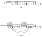
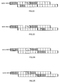
- FIG. 1 the GPRS TDMA frame structure is illustrated and shows the numbering convention used for uplink and downlink slots. It should be noted that in practice Tx may be advanced relative to Rx due to timing advance in accordance with conventional GSM usage, although this is not shown in the illustration. Thus in practice the amount of time between the first Rx and first Tx of a frame may be reduced by a fraction of a slot from the illustrated value of 3 slots due to timing advance.
- FIG 1 illustrates two successive TDMA frames with receiver (Rx) and transmitter (Tx) slots identified separately.
- the slot positions within the first frame are shown by the numerals 1 through to 8 with the transmission and reception slots offset by a margin of three slots. This is in accordance with the convention that that the first transmit frame in a TDMA lags the first receive frame by an offset of 3 (thus ordinary single slot GSM can be regarded as a particular case in which only slot 1 of transmit and receive is used).
- T ra 3GPP TS 05.02 6.4.2.2. That is to say that all adjacent cell signal level measurements are taken just before the first receive slot and not before the transmit slot.
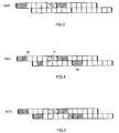
- a pair of a receive frame and a transmit frame corresponds to each other on a 1-1 basis with a predetermined offset, where transmission is started from a transmit slot having the same number as that of a receive slot in which a valid USF was received.
- the starting of transmission is done from the next transmission frame of the transmission frame corresponding to the reception frame in which a valid USF is received.
- the number of transmit slots for transmission in a transmit frame equals to the slot numbers allocated to the transmit frame (N), and slots to be transmitted in a transmit frame are always consecutive. The starting position of transmit slots is maintained until the reception of the next valid USF.
- R3T0 indicates receive slots of 3 and transmit slots of 0, while R3T2 indicates receive slots of 3 and transmit slots of 2.
- the starting position of transmit slots in the next transmission frame is Tx slot 2.
- the number of transmit slots to be transmitted is 2, which is the same as the number of the allocated transmitted slots, and these two transmit slots are consecutive.
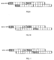
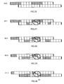
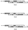
- Figures 3 to 5 show steady state extended dynamic allocations for 2 PDCH according to the annotations and the turnaround (and adjacent cell signal level measurement) intervals are marked.
- consecutive two frames are in the same state because they are in a steady state.
- R2T0 indicates that the number of receive slots is 2 and the number of transmit slots is 0.
- T tb is unnecessary because there is no transmission.
- T ra starts at two slots before the reception of the next frame.
- FIG 4 illustrates steady state extended dynamic allocation for R2T1 (Rx 2 slots, Tx 1 slot).
- a valid USF 43 received on Rx slot 2 allows one Tx slot on the next uplink frame.
- the starting position of the allowed transmit slot is Tx slot 2, which has the same slot number as the reception position of the valid USF 43 (Rx slot 2) in accordance with the extended dynamic allocation described above.
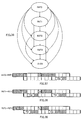
- Figure 6 is a state transition diagram for 2 PDCH extended dynamic allocations and shows all of the allowed states. Specifically, as illustrated in Figure 6, an aggregate of five state transitions are allowed, including, from R2T0 (Rx 2 slots, Tx 0 slot) to R2T1 (Rx 2 slots, Tx 1 slot), from R2T0 to R2T2 (Rx 2 slots, Tx 2 slots), from R2T1 to R2T0, from R2T1 to R2T2, and from R2T2 to R2T0.
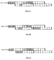
- Figures 7 through to 11 show the slot positions and applicable turnaround (and adjacent cell signal level measurement) intervals for the transitions of Figure 6.
- Figure 7 illustrates a state transition from R2T1 to R2T2.
- the starting position of transmit slots in the next transmission frame is Tx slot 1.
- Steady state 3 PDCH extended dynamic allocations are shown in Figures 12 to 15.
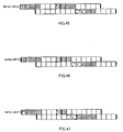
- the state transitions for 3PDCH are shown in Figure 16 and the corresponding slot positions and turnaround (and adjacent cell signal level measurement) intervals in Figures 17 to 25. It can be seen that for all of the illustrations no impediment to slot allocation arises from the application of the turnaround (and adjacent cell signal level measurement) intervals.
- periods for adjacent cell signal level measurement and turnaround are re-allocated to increase the availability of uplink resources when the uplink resources are otherwise constrained by prescribed allocations.
- This procedure is implemented in the mobile station which when using the extended dynamic allocation method, and on receiving an allocation of PDCH numbering "N", must perform the comparison above in order to time the radio link measurement procedure correctly.
- the procedure performed by the network equipment is that when allocating a number of PDCHs "N", it recognises that when N satisfies the condition (XX) above it must take into account the capability of the mobile station to perform adjacent cell signal level measurements using T ta and provided that: N + T rb + 3 ⁇ 8, is capable of allocating such a number of PDCHs.
- the method may be applied successfully to the remaining steady states shown in Figures 33, 34 and 35. Furthermore the method is effective for all of the 4 slot state transitions shown in the state transition diagram Figure 6. Illustrations of the 4 slot state transitions are given in Figures 37 through to 50.
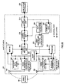
- Figure 51 is a block diagram for a mobile station (MS) which is adaptable to the present embodiment.
- a mobile station (wireless data communication terminal) 100 allows the bi-directional transfer of data between a base station 200 and an external data source and sink 130.
- the base station 200 transmits GPRS signals to the mobile station 100.
- the GPRS signals are received on the receive antenna 102, and are demodulated to baseband ones by a radio frequency demodulator 108.
- the radio frequency demodulator 108 delivers the baseband signals to a baseband data receiver 106.
- the baseband data receiver 106 delivers the received baseband data to a demultiplexer 110.
- the demultiplexer 110 selects either an NCELL measurement unit 112 or a Layer 2 protocol unit 114 to process the above data, depending on its control input from a timing controller 120.
- the downlink baseband data is destined for the NCELL measurement unit 112
- this unit performs adjacent cell signal level measurement, and transmits the resulting information to a Layer 3 protocol unit 116.
- the Layer 3 protocol unit 116 in turn transmits the data to the base station 200 via the uplink.
- Downlink baseband data to be used for adjacent cell signal level measurement is routed to the Layer 3 protocol unit 116.
- the Layer 3 protocol unit 116 separates user plane data and control plane data.
- the user data is sent to a terminal interface unit 118.
- the terminal interface unit 118 sends the data to an external data source and sink 130.
- Control plane data is used to perform internal control functions.
- any GPRS slot allocation frames sent from the base station 200 are used to send parameter data to a slot allocation calculator 128.
- the slot allocation calculator 128 calculates which TDMA slots shall be used for data reception, data transmission, and adjacent cell signal level measurement purposes. This information is sent to a timing controller setting calculator 126.
- the timing controller setting calculator 126 in turn reconfigures a timing controller 120 so as to perform each operation of receive preparation, transmit preparation, and adjacent cell signal level measurement at the correct time.
- Figure 52 is a flowchart illustrating an operation example of the slot allocation calculator 128.
- step S1000 parameter Tra_flag is set into 1, while parameters Tr and Tt are set to values of Tra[class] and Ttb[class] respectively.
- Tra_flag is a parameter indicating which one of T ra and T ta should be used as the interval accommodating adjacent cell signal level measurement, where the parameter indicates that T ra should be used when set to 1, and that T ta should be used when set to 0.
- Tra[class] and Ttb[class] are values of T ra and T tb allocated to class (multislot class of a mobile station), which is an input parameter, respectively.
- the number of the class is a property of the mobile station.
- the value of T ra , T tb corresponding to each class is pre-stored in the format of, for example, Table 1.
- parameter Rxmin is set to the value of Tr as set in step S1000.
- Rxmin is a parameter indicating the number of the first slot in downlink receive slots.
- step S1200 the number of transmit slots (Tx) and the number of receive slots (Rx) is compared with each other. As the result of the comparison, if Tx ⁇ Rx (S1200: NO), the process goes to step S1300, whereas if Tx ⁇ Rx (S1200: YES), it moves on to step S1500. It is noted that each value of Tx, Rx is included in the radio resource control plane data from the upper layer.
- step S1300 it is further judged whether Rx + Tt is less than 3 or not.
- "3" is the number of slots for downlink and uplink offset.
- parameter Txmin is set to Tr + 3.
- parameter Txmin is set to Tr + Rx + 3.
- Txmin is a parameter indicating the number of the first slot in uplink transmit slots. Incidentally, the value set in step S1000 is used for Tr.
- step S1600 parameter Txmax is set to Txmin + Tx.
- Txmax is a parameter indicating the number of the next slot of the last slot in uplink transmit slots.
- the value set in step S1400 or step S1500 is used for Txmin.
- step S1700 it is judged whether to end processing or not. Specifically, it is judged whether the processing from step S1100 through step S1600 is the first execution or the second execution. As the result of the judgment, if the processing is not ended, that is, if the processing from step S1100 through step S1600 is the first execution (S1700: NO), the process goes to step S1800, whereas if the processing from step S1100 through step S1600 is the second execution (S1700: YES), a string of processing is ended.
- step S1800 it is judged whether Txmax set in step S1600 is less than 8 or not.
- "8" is the number of slots contained in one frame.
- step S1900 parameter Tra_flag is set into 0, while parameters Tr and Tt are set to values of Trb[class] and Tta[class] respectively, and after that, the process goes to step S1100 to repeat processing from step S1100 through step S1600.
- Trb[class] and Tta[class] are values of T rb and T ta allocated to class, which is an input parameter, respectively.
- the number of class is included in the radio resource control plane data from the upper layer, and in addition, the value of T rb , T ta corresponding to each class is pre-stored in the format of Table 1. Incidentally, upon completion of the processing from step S1100 through step S1600 (S1700: YES), the string of processing is ended.
- each value of parameters at the time of the end, Tra_flag, Rxmin, Txmin, and Txmax, is outputted as information.
- T ra As a period accommodating adjacent cell signal level measurement, that is, whether it is possible to use T ra and T tb as a combination of intervals. Specifically, if the number of downlink receive slots (Rx) is greater than the number of uplink transmit slots (Tx) (S1200: YES), and if Rx + Tt is equal to or greater than 3 (S1300: NO), Txmin is set to Tr + Rx + Tt (S1500), and otherwise, Txmin is set to Tr + 3 (S1400). Then, Txmax is set to Txmin + Tx (S1600).
- Txmax is equal to or less than 8 (S1800: YES)
- T ra is used as a period accommodating adjacent cell signal level measurement, that is, T ra and T tb is used as a combination of intervals.
- Txmax exceeds 8 (S1800: NO)
- T ta is used as a period accommodating adjacent cell signal level measurement, that is, T rb and T ta is used as a combination of intervals.
- step S1100 through step S1600 assumes the processing in step S1100 through step S1600 to be reexecuted once again after step S1900
- the invention is not limited to such a case. If any parameters other than Tra_flag (for example, Rxmin, Txmin, Txmax, etc.) are unnecessary as output, that is, if it is just enough to set Tra_flag only, the processing may be ended immediately without repeating any processing from step S1100 through step S1600 after step S1900.
- Tra_flag for example, Rxmin, Txmin, Txmax, etc.
- the timing controller 120 is responsible for determining and controlling the timing of the transmission and reception of signals toward the base station 200, and the reception of measurement data.
- User data transmitted from an external data source and sink 130 is accepted by a terminal interface unit 118, and given to a Layer 3 protocol unit 116.
- the Layer 3 protocol unit 116 multiplexes the data with any protocol control data, and transmits it via a Layer 2 protocol unit 114.
- the Layer 2 protocol unit 114 in turn transmits the multiplexed data to a baseband transmitter 124. Subsequently, the multiplexed data is modulated by a radio frequency modulator 122, and then is transmitted over a transmit antenna 104.
- Figure 53 is a block diagram for a base station which is adaptable to the present embodiment.
- a wireless base station 200 allows the bi-directional transfer of data between a plurality of mobile stations 100 and an external base station controller (BSC: Base Station Controller) 230.
- BSC Base Station Controller
- Each mobile station 100 transmits precisely-timed GPRS signals to the base station 200.
- the GPRS signals are received on the receive antenna 202, and are demodulated to baseband ones by a radio frequency demodulator 208.
- the radio frequency demodulator 208 delivers the baseband signals to a baseband data receiver 206. If multiple receive frequencies are used, there is one set of radio frequency demodulator 208 and baseband data receiver 206 per frequency.
- the baseband data receiver 206 delivers the received baseband data to a multiplexer MS 210.
- the multiplexer MS 210 marks which MS the data has arrived from depending on its control input from a timing controller 220, and forwards all data to a Layer 2 protocol unit 214.
- the Layer 2 protocol unit 214 maintains a separate context for each mobile station 100.
- Downlink baseband data to be used for NCELL measurement is routed to a Layer 3 protocol unit 216.
- the Layer 3 protocol unit 216 maintains a separate context for each mobile station 100.
- the Layer 3 protocol unit 216 separates user plane data and radio resource control plane data.
- User data and radio resource control plane data is sent to a BSC interface unit 218.
- the BSC interface unit 218 sends the data to an external base station controller 230.
- Radio resource control plane data is used to perform internal control functions.
- a slot allocation calculator 228 calculates, typically according to the data rate required, which GPRS slots are allocated for each mobile station 100. This information is sent to the Layer 3 protocol unit 216. The Layer 3 protocol unit 216 sends allocation information to the mobile station 100. This information is also sent to a timing controller setting calculator 226.
- other MS slot allocator 232 receives necessary data from the external Base station controller 230 via the BSC interface unit 218, and calculates allocation information for other mobile stations. This information is also sent to the timing controller setting calculator 226. The timing controller setting calculator 226 in turn reconfigures a timing controller 220 so as to perform each of receive and transmit actions towards each mobile station 100 at the correct time.
- the timing controller 220 is responsible for determining and controlling the timing of the transmission and reception of signals toward the mobile station 100. In accordance with the calculation result of the slot allocation calculator 228, the timing controller 220 controls the precise timing and behaviour of the radio frequency modulator 222, radio frequency demodulator 208, baseband data receiver 206, baseband transmitter 224, multiplexer MS 210, and demultiplexer MS 234.
- User data and control data transmitted from a base station controller 230 is accepted by a BSC interface unit 218, and given to a Layer 3 protocol unit 216.
- the Layer 3 protocol unit 216 multiplexes the data with any radio resource control data, and transmits it via a Layer 2 protocol unit 214.
- the Layer 2 protocol unit 214 in turn transmits the multiplexed data to a demultiplexer MS 234.
- the demultiplexer MS 234 provides the data for each mobile station 100 on the correct TDMA slot to the correct baseband transmitter 224. Subsequently, the data is modulated by a radio frequency modulator 222, and then is transmitted over a transmit antenna 204. If multiple transmit frequencies are used, there is one set of radio frequency modulator 222 and baseband data transmitter 224 per frequency.
Landscapes
- Engineering & Computer Science (AREA)
- Computer Networks & Wireless Communication (AREA)
- Signal Processing (AREA)
- Mobile Radio Communication Systems (AREA)
- Time-Division Multiplex Systems (AREA)
- Data Exchanges In Wide-Area Networks (AREA)
- Radio Relay Systems (AREA)
Applications Claiming Priority (2)
| Application Number | Priority Date | Filing Date | Title |
|---|---|---|---|
| GB0307585A GB2400271B (en) | 2003-04-02 | 2003-04-02 | Dynamic resource allocation in packet data transfer |
| GB0307585 | 2003-04-02 |
Publications (2)
| Publication Number | Publication Date |
|---|---|
| EP1471757A2 true EP1471757A2 (de) | 2004-10-27 |
| EP1471757A3 EP1471757A3 (de) | 2005-03-30 |
Family
ID=9956020
Family Applications (4)
| Application Number | Title | Priority Date | Filing Date |
|---|---|---|---|
| EP04000151A Withdrawn EP1465448A3 (de) | 2003-04-02 | 2004-01-07 | Dynamische Verteilung im Paketdatentransfer |
| EP05009522A Expired - Lifetime EP1558051B1 (de) | 2003-04-02 | 2004-01-07 | Dynamische Verteilung von Mitteln in Paketdatentransfer |
| EP04000180A Expired - Lifetime EP1465449B1 (de) | 2003-04-02 | 2004-01-07 | Dynamische Verteilung von Mitteln im Paketdatentransfer |
| EP04008085A Withdrawn EP1471757A3 (de) | 2003-04-02 | 2004-04-02 | Dynamische Verteilung im Paketdatentransfer |
Family Applications Before (3)
| Application Number | Title | Priority Date | Filing Date |
|---|---|---|---|
| EP04000151A Withdrawn EP1465448A3 (de) | 2003-04-02 | 2004-01-07 | Dynamische Verteilung im Paketdatentransfer |
| EP05009522A Expired - Lifetime EP1558051B1 (de) | 2003-04-02 | 2004-01-07 | Dynamische Verteilung von Mitteln in Paketdatentransfer |
| EP04000180A Expired - Lifetime EP1465449B1 (de) | 2003-04-02 | 2004-01-07 | Dynamische Verteilung von Mitteln im Paketdatentransfer |
Country Status (12)
| Country | Link |
|---|---|
| US (3) | US7020105B2 (de) |
| EP (4) | EP1465448A3 (de) |
| JP (4) | JP3590055B2 (de) |
| KR (3) | KR20050119184A (de) |
| CN (3) | CN1768490A (de) |
| AT (2) | ATE403357T1 (de) |
| BR (3) | BRPI0409163A (de) |
| DE (2) | DE602004000274T2 (de) |
| DK (1) | DK1465449T3 (de) |
| ES (1) | ES2256801T3 (de) |
| GB (2) | GB2400271B (de) |
| WO (3) | WO2004091245A2 (de) |
Families Citing this family (62)
| Publication number | Priority date | Publication date | Assignee | Title |
|---|---|---|---|---|
| US7295509B2 (en) | 2000-09-13 | 2007-11-13 | Qualcomm, Incorporated | Signaling method in an OFDM multiple access system |
| US9130810B2 (en) | 2000-09-13 | 2015-09-08 | Qualcomm Incorporated | OFDM communications methods and apparatus |
| WO2005006675A2 (en) | 2003-07-10 | 2005-01-20 | Matsushita Electric Industrial Co., Ltd. | Wireless communication system and communication method |
| WO2005052660A1 (ja) | 2003-11-28 | 2005-06-09 | Nhk Spring Co., Ltd. | 多チャンネルアレイ導波路回折格子型合分波器およびアレイ導波路と出力導波路の接続方法 |
| US9148256B2 (en) | 2004-07-21 | 2015-09-29 | Qualcomm Incorporated | Performance based rank prediction for MIMO design |
| US9137822B2 (en) | 2004-07-21 | 2015-09-15 | Qualcomm Incorporated | Efficient signaling over access channel |
| US8095141B2 (en) | 2005-03-09 | 2012-01-10 | Qualcomm Incorporated | Use of supplemental assignments |
| US9246560B2 (en) | 2005-03-10 | 2016-01-26 | Qualcomm Incorporated | Systems and methods for beamforming and rate control in a multi-input multi-output communication systems |
| US9154211B2 (en) | 2005-03-11 | 2015-10-06 | Qualcomm Incorporated | Systems and methods for beamforming feedback in multi antenna communication systems |
| US8446892B2 (en) | 2005-03-16 | 2013-05-21 | Qualcomm Incorporated | Channel structures for a quasi-orthogonal multiple-access communication system |
| US9143305B2 (en) | 2005-03-17 | 2015-09-22 | Qualcomm Incorporated | Pilot signal transmission for an orthogonal frequency division wireless communication system |
| US9520972B2 (en) | 2005-03-17 | 2016-12-13 | Qualcomm Incorporated | Pilot signal transmission for an orthogonal frequency division wireless communication system |
| US9461859B2 (en) | 2005-03-17 | 2016-10-04 | Qualcomm Incorporated | Pilot signal transmission for an orthogonal frequency division wireless communication system |
| US9184870B2 (en) | 2005-04-01 | 2015-11-10 | Qualcomm Incorporated | Systems and methods for control channel signaling |
| US9036538B2 (en) | 2005-04-19 | 2015-05-19 | Qualcomm Incorporated | Frequency hopping design for single carrier FDMA systems |
| US9408220B2 (en) | 2005-04-19 | 2016-08-02 | Qualcomm Incorporated | Channel quality reporting for adaptive sectorization |
| US8879511B2 (en) | 2005-10-27 | 2014-11-04 | Qualcomm Incorporated | Assignment acknowledgement for a wireless communication system |
| US8611284B2 (en) | 2005-05-31 | 2013-12-17 | Qualcomm Incorporated | Use of supplemental assignments to decrement resources |
| US8565194B2 (en) | 2005-10-27 | 2013-10-22 | Qualcomm Incorporated | Puncturing signaling channel for a wireless communication system |
| US8462859B2 (en) | 2005-06-01 | 2013-06-11 | Qualcomm Incorporated | Sphere decoding apparatus |
| US9179319B2 (en) | 2005-06-16 | 2015-11-03 | Qualcomm Incorporated | Adaptive sectorization in cellular systems |
| US8599945B2 (en) | 2005-06-16 | 2013-12-03 | Qualcomm Incorporated | Robust rank prediction for a MIMO system |
| US8885628B2 (en) | 2005-08-08 | 2014-11-11 | Qualcomm Incorporated | Code division multiplexing in a single-carrier frequency division multiple access system |
| US9209956B2 (en) | 2005-08-22 | 2015-12-08 | Qualcomm Incorporated | Segment sensitive scheduling |
| US20070041457A1 (en) | 2005-08-22 | 2007-02-22 | Tamer Kadous | Method and apparatus for providing antenna diversity in a wireless communication system |
| US8644292B2 (en) | 2005-08-24 | 2014-02-04 | Qualcomm Incorporated | Varied transmission time intervals for wireless communication system |
| US9136974B2 (en) | 2005-08-30 | 2015-09-15 | Qualcomm Incorporated | Precoding and SDMA support |
| US7640021B2 (en) * | 2005-09-13 | 2009-12-29 | Interdigital Technology Corporation | Method and apparatus for radio resource allocation in a wireless communication system |
| US8045512B2 (en) | 2005-10-27 | 2011-10-25 | Qualcomm Incorporated | Scalable frequency band operation in wireless communication systems |
| US8693405B2 (en) | 2005-10-27 | 2014-04-08 | Qualcomm Incorporated | SDMA resource management |
| US9088384B2 (en) | 2005-10-27 | 2015-07-21 | Qualcomm Incorporated | Pilot symbol transmission in wireless communication systems |
| US9225416B2 (en) | 2005-10-27 | 2015-12-29 | Qualcomm Incorporated | Varied signaling channels for a reverse link in a wireless communication system |
| US9225488B2 (en) | 2005-10-27 | 2015-12-29 | Qualcomm Incorporated | Shared signaling channel |
| US8582509B2 (en) | 2005-10-27 | 2013-11-12 | Qualcomm Incorporated | Scalable frequency band operation in wireless communication systems |
| US9144060B2 (en) | 2005-10-27 | 2015-09-22 | Qualcomm Incorporated | Resource allocation for shared signaling channels |
| US9210651B2 (en) | 2005-10-27 | 2015-12-08 | Qualcomm Incorporated | Method and apparatus for bootstraping information in a communication system |
| US9172453B2 (en) | 2005-10-27 | 2015-10-27 | Qualcomm Incorporated | Method and apparatus for pre-coding frequency division duplexing system |
| US8477684B2 (en) | 2005-10-27 | 2013-07-02 | Qualcomm Incorporated | Acknowledgement of control messages in a wireless communication system |
| US8204072B2 (en) | 2005-11-07 | 2012-06-19 | Agency For Science, Technology And Research | Method and devices for determining available frequency ranges |
| ATE393554T1 (de) * | 2005-11-10 | 2008-05-15 | Research In Motion Ltd | Verfahren und vorrichtung zur kanalzuteilung für datenkommunikation in einem funk- kommunikationssystem |
| US8582548B2 (en) | 2005-11-18 | 2013-11-12 | Qualcomm Incorporated | Frequency division multiple access schemes for wireless communication |
| US8831607B2 (en) | 2006-01-05 | 2014-09-09 | Qualcomm Incorporated | Reverse link other sector communication |
| US8179855B2 (en) | 2006-02-07 | 2012-05-15 | Research In Motion Limited | Method, and associated apparatus, for communicating data at reduced transmission latency in radio communication system having slotted interface |
| ATE403363T1 (de) * | 2006-02-07 | 2008-08-15 | Research In Motion Ltd | Kommunikation von daten mit verringerter übertragungslatenzzeit in einem funkkommunikationssystem mit tdma radioschnittstelle |
| WO2007112761A1 (en) * | 2006-03-31 | 2007-10-11 | Matsushita Electric Industrial Co., Ltd. | Scheduling radio blocks in a multi-carrier tdma mobile communication system |
| US8107968B2 (en) * | 2006-12-11 | 2012-01-31 | Nokia Corporation | Radio transmission scheduling according to multiradio control in a radio modem |
| GB0702325D0 (en) * | 2007-02-07 | 2007-03-21 | Siemens Ag | Uplink allocation strategies |
| JP4909914B2 (ja) * | 2008-01-15 | 2012-04-04 | 株式会社日立製作所 | 無線端末 |
| CN101971662B (zh) * | 2008-01-30 | 2014-07-23 | 爱立信电话股份有限公司 | 用于tdd系统中移动终端的配置测量时隙的方法及设备 |
| JP5416140B2 (ja) * | 2008-02-08 | 2014-02-12 | ゼットティーイー(ユーエスエー)インコーポレーテッド | Tdd無線システムにおけるダウンリンク/アップリンク割当比の動的調整 |
| WO2010066067A1 (zh) * | 2008-12-12 | 2010-06-17 | 上海贝尔阿尔卡特股份有限公司 | 移动通信系统中的帧汇聚方法 |
| US9325618B1 (en) * | 2008-12-31 | 2016-04-26 | Qualcomm Incorporated | Dynamic management of shared transmission opportunities |
| KR101544150B1 (ko) * | 2009-03-26 | 2015-08-12 | 삼성전자주식회사 | 무선통신시스템에서 서비스 품질을 향상시키기 위한 장치 및 방법 |
| KR101498066B1 (ko) | 2009-04-14 | 2015-03-03 | 엘지전자 주식회사 | 무선 통신 시스템에서 데이터 전송 및 수신 방법 |
| SG175269A1 (en) * | 2009-04-21 | 2011-11-28 | Research In Motion Ltd | System and method for adjusting monitoring of timeslots during data transmission |
| JP5505178B2 (ja) * | 2009-11-02 | 2014-05-28 | 日本電気株式会社 | 無線通信装置、無線通信装置の受信レベル判別方法及びプログラム |
| US9538434B2 (en) * | 2010-04-06 | 2017-01-03 | Telefonaktiebolaget Lm Ericsson (Publ) | Method and arrangement in a wireless communication system |
| DE102010025796B4 (de) * | 2010-07-01 | 2012-07-12 | Infineon Technologies Ag | Verfahren zum Empfangen von Synchronisationssignalen eines Mobilfunknetzwerks und Sende-/Empfangseinrichtung für Mobilfunksignale |
| WO2012079604A1 (en) | 2010-12-15 | 2012-06-21 | Telefonaktiebolaget L M Ericsson (Publ) | Technique for inter-cell interference coordination in a heterogeneous communication network |
| JP6171443B2 (ja) * | 2013-03-21 | 2017-08-02 | 富士通株式会社 | データ転送制御方法、中継装置、及びデータ転送制御装置 |
| US20150016349A1 (en) * | 2013-07-11 | 2015-01-15 | Qualcomm Incorporated | Methods and apparatus for enhanced uplink communication |
| US12413994B2 (en) | 2019-05-03 | 2025-09-09 | Telefonaktiebolaget Lm Ericsson (Publ) | Method and apparatus for controlling transmission on preconfigured uplink resources in a wireless communication network |
Family Cites Families (14)
| Publication number | Priority date | Publication date | Assignee | Title |
|---|---|---|---|---|
| US30956A (en) * | 1860-12-18 | Operating the valves of steam-engines | ||
| US5493563A (en) | 1993-07-26 | 1996-02-20 | Motorola, Inc. | Method and apparatus for mobile assisted handoff in a communication system |
| FI101332B (fi) * | 1995-12-18 | 1998-05-29 | Nokia Telecommunications Oy | Epäjatkuvalähetys monikanavaisessa suurinopeuksisessa datasiirrossa |
| FI103629B1 (fi) | 1996-10-10 | 1999-07-30 | Nokia Telecommunications Oy | Menetelmä puheluliikenteen kuuman pisteen määrittämiseksi solukkomatkaviestinjärjestelmän solussa |
| FI104680B (fi) * | 1997-01-09 | 2000-04-14 | Nokia Mobile Phones Ltd | Menetelmä naapurisolutiedon määrittämiseksi solukkoverkossa ja matkaviestin |
| FR2764463B1 (fr) | 1997-06-10 | 1999-09-24 | Alsthom Cge Alcatel | Procede d'allocation de canaux de transmission a une station mobile, notamment en mode semi-duplex, dans un reseau de telecommunications mobiles, en mode paquet |
| US5966657A (en) * | 1997-07-24 | 1999-10-12 | Telefonaktiebolaget L M Ericsson (Publ) | Method and system for radio frequency measurement and automatic frequency planning in a cellular radio system |
| FI110351B (fi) * | 1997-11-11 | 2002-12-31 | Nokia Corp | Menetelmä radiosignaalin lähetyksen aikavälien tahdistamiseksi sekä menetelmän mukainen radiopuhelinverkko, tukiasema-alajärjestelmä ja matkaviestin |
| US6600758B1 (en) * | 1999-05-28 | 2003-07-29 | Telefonaktiebolaget Lm Ericsson (Publ) | Methods and apparatus for measuring control carrier signal strength in wireless communications systems employing discontinuous control carrier transmissions |
| US6487415B1 (en) * | 1999-07-19 | 2002-11-26 | Lucent Technologies Inc. | Method for initiating call blocking based upon pilot fraction |
| US6996083B1 (en) * | 1999-12-10 | 2006-02-07 | Lucent Technologies Inc. | Burst based access and assignment method for providing real-time services |
| US7177298B2 (en) * | 2000-01-07 | 2007-02-13 | Gopal Chillariga | Dynamic channel allocation in multiple-access communication systems |
| ITMI20010721A1 (it) | 2001-04-04 | 2002-10-04 | Siemens Inf & Comm Networks | Metodo per offrire servizi a pacchetto su risorse radio condivise da piu' utenti in un sistema di tipo tdd-cdma |
| EP1261227A1 (de) * | 2001-05-21 | 2002-11-27 | Motorola, Inc. | Verfahren und Gerät zur erhöhten Informationsübertragung in einem Kommunikationssystem |
-
2003
- 2003-04-02 GB GB0307585A patent/GB2400271B/en not_active Expired - Fee Related
- 2003-04-02 GB GB0415066A patent/GB2400280B/en not_active Expired - Fee Related
-
2004
- 2004-01-07 AT AT05009522T patent/ATE403357T1/de not_active IP Right Cessation
- 2004-01-07 EP EP04000151A patent/EP1465448A3/de not_active Withdrawn
- 2004-01-07 DE DE602004000274T patent/DE602004000274T2/de not_active Expired - Lifetime
- 2004-01-07 DE DE602004015403T patent/DE602004015403D1/de not_active Expired - Lifetime
- 2004-01-07 ES ES04000180T patent/ES2256801T3/es not_active Expired - Lifetime
- 2004-01-07 AT AT04000180T patent/ATE314795T1/de not_active IP Right Cessation
- 2004-01-07 EP EP05009522A patent/EP1558051B1/de not_active Expired - Lifetime
- 2004-01-07 DK DK04000180T patent/DK1465449T3/da active
- 2004-01-07 EP EP04000180A patent/EP1465449B1/de not_active Expired - Lifetime
- 2004-02-26 KR KR1020057018757A patent/KR20050119184A/ko not_active Withdrawn
- 2004-02-26 BR BRPI0409163-9A patent/BRPI0409163A/pt not_active Application Discontinuation
- 2004-02-26 KR KR1020057018572A patent/KR100730861B1/ko not_active Expired - Fee Related
- 2004-02-26 WO PCT/JP2004/002308 patent/WO2004091245A2/en not_active Ceased
- 2004-02-26 CN CNA2004800087955A patent/CN1768490A/zh active Pending
- 2004-02-26 WO PCT/JP2004/002307 patent/WO2004091116A2/en not_active Ceased
- 2004-02-26 BR BRPI0408579-5A patent/BRPI0408579A/pt not_active Application Discontinuation
- 2004-02-26 CN CNA2004800087669A patent/CN1799274A/zh not_active Withdrawn
- 2004-02-27 US US10/787,258 patent/US7020105B2/en not_active Expired - Lifetime
- 2004-02-27 US US10/787,242 patent/US20040208148A1/en not_active Abandoned
- 2004-03-03 JP JP2004059876A patent/JP3590055B2/ja not_active Expired - Fee Related
- 2004-03-03 JP JP2004059871A patent/JP2004312703A/ja active Pending
- 2004-03-30 JP JP2004100135A patent/JP2004312728A/ja active Pending
- 2004-03-31 CN CNA2004800091109A patent/CN1768491A/zh active Pending
- 2004-03-31 WO PCT/JP2004/004649 patent/WO2004091118A2/en not_active Ceased
- 2004-03-31 KR KR1020057018780A patent/KR20050114712A/ko not_active Withdrawn
- 2004-03-31 BR BRPI0409076-4A patent/BRPI0409076A/pt not_active Application Discontinuation
- 2004-04-01 US US10/814,784 patent/US20050135327A1/en not_active Abandoned
- 2004-04-02 EP EP04008085A patent/EP1471757A3/de not_active Withdrawn
- 2004-10-14 JP JP2004300724A patent/JP3629032B1/ja not_active Expired - Fee Related
Also Published As
Similar Documents
| Publication | Publication Date | Title |
|---|---|---|
| EP1471757A2 (de) | Dynamische Verteilung im Paketdatentransfer | |
| CN1806459B (zh) | 用于分组数据传输的扩展的动态资源分配 |
Legal Events
| Date | Code | Title | Description |
|---|---|---|---|
| PUAI | Public reference made under article 153(3) epc to a published international application that has entered the european phase |
Free format text: ORIGINAL CODE: 0009012 |
|
| AK | Designated contracting states |
Kind code of ref document: A2 Designated state(s): AT BE BG CH CY CZ DE DK EE ES FI FR GB GR HU IE IT LI LU MC NL PL PT RO SE SI SK TR |
|
| AX | Request for extension of the european patent |
Extension state: AL HR LT LV MK |
|
| PUAL | Search report despatched |
Free format text: ORIGINAL CODE: 0009013 |
|
| AK | Designated contracting states |
Kind code of ref document: A3 Designated state(s): AT BE BG CH CY CZ DE DK EE ES FI FR GB GR HU IE IT LI LU MC NL PL PT RO SE SI SK TR |
|
| AX | Request for extension of the european patent |
Extension state: AL HR LT LV MK |
|
| RIC1 | Information provided on ipc code assigned before grant |
Ipc: 7H 04B 7/26 A |
|
| 17P | Request for examination filed |
Effective date: 20050906 |
|
| AKX | Designation fees paid |
Designated state(s): AT BE BG CH CY CZ DE DK EE ES FI FR GB GR HU IE IT LI LU MC NL PL PT RO SE SI SK TR |
|
| STAA | Information on the status of an ep patent application or granted ep patent |
Free format text: STATUS: THE APPLICATION IS DEEMED TO BE WITHDRAWN |
|
| 18D | Application deemed to be withdrawn |
Effective date: 20060705 |